EP1003323A2 - Dispositif de lecture d'image et procédé de lecture d'image - Google Patents
Dispositif de lecture d'image et procédé de lecture d'image Download PDFInfo
- Publication number
- EP1003323A2 EP1003323A2 EP99121979A EP99121979A EP1003323A2 EP 1003323 A2 EP1003323 A2 EP 1003323A2 EP 99121979 A EP99121979 A EP 99121979A EP 99121979 A EP99121979 A EP 99121979A EP 1003323 A2 EP1003323 A2 EP 1003323A2
- Authority
- EP
- European Patent Office
- Prior art keywords
- original
- transparent member
- light
- image reader
- optical path
- Prior art date
- Legal status (The legal status is an assumption and is not a legal conclusion. Google has not performed a legal analysis and makes no representation as to the accuracy of the status listed.)
- Granted
Links
Images


Classifications
-
- H—ELECTRICITY
- H04—ELECTRIC COMMUNICATION TECHNIQUE
- H04N—PICTORIAL COMMUNICATION, e.g. TELEVISION
- H04N1/00—Scanning, transmission or reproduction of documents or the like, e.g. facsimile transmission; Details thereof
- H04N1/024—Details of scanning heads ; Means for illuminating the original
- H04N1/028—Details of scanning heads ; Means for illuminating the original for picture information pick-up
- H04N1/02815—Means for illuminating the original, not specific to a particular type of pick-up head
- H04N1/02845—Means for illuminating the original, not specific to a particular type of pick-up head using an elongated light source, e.g. tubular lamp, LED array
- H04N1/02855—Means for illuminating the original, not specific to a particular type of pick-up head using an elongated light source, e.g. tubular lamp, LED array in combination with a light guide, e.g. optical fibre, glass plate
-
- H—ELECTRICITY
- H04—ELECTRIC COMMUNICATION TECHNIQUE
- H04N—PICTORIAL COMMUNICATION, e.g. TELEVISION
- H04N1/00—Scanning, transmission or reproduction of documents or the like, e.g. facsimile transmission; Details thereof
- H04N1/024—Details of scanning heads ; Means for illuminating the original
- H04N1/028—Details of scanning heads ; Means for illuminating the original for picture information pick-up
- H04N1/02815—Means for illuminating the original, not specific to a particular type of pick-up head
- H04N1/0288—Means for illuminating the original, not specific to a particular type of pick-up head using a two-dimensional light source, e.g. two-dimensional LED array
-
- H—ELECTRICITY
- H04—ELECTRIC COMMUNICATION TECHNIQUE
- H04N—PICTORIAL COMMUNICATION, e.g. TELEVISION
- H04N1/00—Scanning, transmission or reproduction of documents or the like, e.g. facsimile transmission; Details thereof
- H04N1/04—Scanning arrangements, i.e. arrangements for the displacement of active reading or reproducing elements relative to the original or reproducing medium, or vice versa
- H04N1/0464—Scanning arrangements, i.e. arrangements for the displacement of active reading or reproducing elements relative to the original or reproducing medium, or vice versa capable of performing non-simultaneous scanning at more than one scanning station
- H04N1/0467—Scanning arrangements, i.e. arrangements for the displacement of active reading or reproducing elements relative to the original or reproducing medium, or vice versa capable of performing non-simultaneous scanning at more than one scanning station the different stations being used for transmissive and reflective originals
-
- H—ELECTRICITY
- H04—ELECTRIC COMMUNICATION TECHNIQUE
- H04N—PICTORIAL COMMUNICATION, e.g. TELEVISION
- H04N1/00—Scanning, transmission or reproduction of documents or the like, e.g. facsimile transmission; Details thereof
- H04N1/04—Scanning arrangements, i.e. arrangements for the displacement of active reading or reproducing elements relative to the original or reproducing medium, or vice versa
- H04N1/10—Scanning arrangements, i.e. arrangements for the displacement of active reading or reproducing elements relative to the original or reproducing medium, or vice versa using flat picture-bearing surfaces
- H04N1/1013—Scanning arrangements, i.e. arrangements for the displacement of active reading or reproducing elements relative to the original or reproducing medium, or vice versa using flat picture-bearing surfaces with sub-scanning by translatory movement of at least a part of the main-scanning components
- H04N1/1017—Scanning arrangements, i.e. arrangements for the displacement of active reading or reproducing elements relative to the original or reproducing medium, or vice versa using flat picture-bearing surfaces with sub-scanning by translatory movement of at least a part of the main-scanning components the main-scanning components remaining positionally invariant with respect to one another in the sub-scanning direction
-
- H—ELECTRICITY
- H04—ELECTRIC COMMUNICATION TECHNIQUE
- H04N—PICTORIAL COMMUNICATION, e.g. TELEVISION
- H04N1/00—Scanning, transmission or reproduction of documents or the like, e.g. facsimile transmission; Details thereof
- H04N1/04—Scanning arrangements, i.e. arrangements for the displacement of active reading or reproducing elements relative to the original or reproducing medium, or vice versa
- H04N1/10—Scanning arrangements, i.e. arrangements for the displacement of active reading or reproducing elements relative to the original or reproducing medium, or vice versa using flat picture-bearing surfaces
- H04N1/1013—Scanning arrangements, i.e. arrangements for the displacement of active reading or reproducing elements relative to the original or reproducing medium, or vice versa using flat picture-bearing surfaces with sub-scanning by translatory movement of at least a part of the main-scanning components
- H04N1/1039—Movement of the main scanning components
- H04N1/1043—Movement of the main scanning components of a sensor array
-
- H—ELECTRICITY
- H04—ELECTRIC COMMUNICATION TECHNIQUE
- H04N—PICTORIAL COMMUNICATION, e.g. TELEVISION
- H04N1/00—Scanning, transmission or reproduction of documents or the like, e.g. facsimile transmission; Details thereof
- H04N1/04—Scanning arrangements, i.e. arrangements for the displacement of active reading or reproducing elements relative to the original or reproducing medium, or vice versa
- H04N1/10—Scanning arrangements, i.e. arrangements for the displacement of active reading or reproducing elements relative to the original or reproducing medium, or vice versa using flat picture-bearing surfaces
- H04N1/1013—Scanning arrangements, i.e. arrangements for the displacement of active reading or reproducing elements relative to the original or reproducing medium, or vice versa using flat picture-bearing surfaces with sub-scanning by translatory movement of at least a part of the main-scanning components
- H04N1/1039—Movement of the main scanning components
- H04N1/1048—Movement of the main scanning components of a lens or lens arrangement
-
- H—ELECTRICITY
- H04—ELECTRIC COMMUNICATION TECHNIQUE
- H04N—PICTORIAL COMMUNICATION, e.g. TELEVISION
- H04N1/00—Scanning, transmission or reproduction of documents or the like, e.g. facsimile transmission; Details thereof
- H04N1/04—Scanning arrangements, i.e. arrangements for the displacement of active reading or reproducing elements relative to the original or reproducing medium, or vice versa
- H04N1/10—Scanning arrangements, i.e. arrangements for the displacement of active reading or reproducing elements relative to the original or reproducing medium, or vice versa using flat picture-bearing surfaces
- H04N1/1013—Scanning arrangements, i.e. arrangements for the displacement of active reading or reproducing elements relative to the original or reproducing medium, or vice versa using flat picture-bearing surfaces with sub-scanning by translatory movement of at least a part of the main-scanning components
- H04N1/1039—Movement of the main scanning components
- H04N1/1052—Movement of the main scanning components of a mirror
-
- H—ELECTRICITY
- H04—ELECTRIC COMMUNICATION TECHNIQUE
- H04N—PICTORIAL COMMUNICATION, e.g. TELEVISION
- H04N1/00—Scanning, transmission or reproduction of documents or the like, e.g. facsimile transmission; Details thereof
- H04N1/04—Scanning arrangements, i.e. arrangements for the displacement of active reading or reproducing elements relative to the original or reproducing medium, or vice versa
- H04N1/19—Scanning arrangements, i.e. arrangements for the displacement of active reading or reproducing elements relative to the original or reproducing medium, or vice versa using multi-element arrays
- H04N1/191—Scanning arrangements, i.e. arrangements for the displacement of active reading or reproducing elements relative to the original or reproducing medium, or vice versa using multi-element arrays the array comprising a one-dimensional [1D] array
- H04N1/192—Simultaneously or substantially simultaneously scanning picture elements on one main scanning line
- H04N1/193—Simultaneously or substantially simultaneously scanning picture elements on one main scanning line using electrically scanned linear arrays, e.g. linear CCD arrays
Definitions
- This invention relates to an image reader and an image reading method.
- this invention is directed to a movable transparent member for improving the focusing of reflection and translucent originals.
- One type of image reader for reading an original of an image, text, etc. is a flat bed type comprising an original document bed made of a transparent plate of glass, etc., placed on the top of a box-type cabinet.
- a drive moves a carriage in parallel with the original document bed and the carriage is placed in the cabinet.
- a light source for reading an opaque (reflection) original, such as paper, and a line sensor comprising an arrangement of a large number of photoelectric conversion elements, are mounted on the carriage. Application light of the light source on the carriage is reflected on the surface of the original on the original document bed and is gathered through a condensing lens on the line sensor.
- a surface light source is placed above the original document bed and light applied from the surface light source and passed through an original is read by the line sensor on the carriage, whereby a translucent original such as a film can also be read.
- an image reader for both reflection and translucent originals generally is provided by adding a light source for translucent originals to an image reader for reflection originals, thus, the focus of a condensing lens of a carriage is set so as to match a reflection original.
- distance D R the distance from the surface of an original document bed 3 on the original side thereof to an original 51
- the focus of the condensing lens of the carriage is set so as to match a position shifted about 0.3 mm to the original side from the original document bed 3.
- the focus depth of the condensing lens is about ⁇ 0.5 mm, thus focus is obtained if the distance from the surface of the original document bed 3 on the original side thereof is in the range of 0 to 0.8 mm or so.
- the original is a translucent original 52 such as a positive film as shown in FIG. 7, the translucent original 52 is stored in a film holder 53 and is further stored in a folder cartridge 54 of an image reader 1, thus distance D P from the surface of the original document bed 3 on the original side thereof to the original 52 becomes about 2.5 mm. Therefore, focus on the translucent original 52 cannot be obtained with the condensing lens focusing on reflection originals; thus, the original is read in a state in which it is slightly out of focus.
- an image reader is used wherein either or both of a photosensor and a condensing lens placed on a carriage and a cabinet are moved in the optical axis direction, whereby the position of the focus of the condensing lens or the optical path length from an original to the condensing lens can be changed seamlessly for always focusing on the original; however, the structure of the image reader is complicated and manufacturing costs are increased.
- an image reader has a transparent member placed so that the transparent member can be inserted into an optical path on which light from an original travels.
- the lens focus position when the transparent member exists on the optical path differs from that when the transparent member does not exist on the optical path. Therefore, the lens can be focused on more than one position, so that if the position of an original placed on an original document bed changes, the lens can be focused on the original. Since the transparent member is simply placed in the optical path, the structure is simple and the manufacturing costs can be reduced.
- the transparent member Since the transparent member is placed in the optical path between the original document bed and the lens, the transparent member does not require high accuracy as compared with the case where the transparent member is placed in the optical path between the lens and a photosensor, for example.
- the transparent member is easily manufactured and the manufacturing costs can be reduced.
- the transparent member may be placed in the proximity of the original document bed.
- the transparent member can be placed in the portion with a small optical path width in the perpendicular direction to the light travel direction.
- the transparent member can be miniaturized and the manufacturing costs can be reduced.
- the transparent member may be shaped like a plate, so as to have a smooth surface and uniform thickness.
- irregular reflection on the surface of the transparent member is prevented and rectilinear propagation of light can be provided, and if the transparent member is inserted into the optical path, necessary resolution can be provided. Since the shape of the transparent member is simple, work is easy and the manufacturing costs can be reduced.
- the transparent member may have antireflection means.
- the antireflection means prevents light passing through the transparent member from being reflected on the surface and the rear face of the transparent member. Therefore, occurrence of a ghost can be prevented.
- the ghost means that light from an original is reflected on the surface or the rear face of the transparent member and the original is read as if another image existed at a position different from the position corresponding to the actual image.
- the transparent member is not inserted into the optical path when light reflected on the surface of the original is read.
- the lens can be focused on the original if the position of the original placed on the original document bed changes.
- a translucent original allowing light to pass through, such as a negative film or a positive film
- light is applied from above the translucent original, namely, from the side opposite to the photosensor with the original document bed between, and light passing through the translucent original can be read.
- the transparent member is inserted into the optical path. Therefore, for example, not only light from a reflection original reflected on the surface of the original placed on the original document bed, but also the translucent original placed above the original document bed, can be read.
- the transparent member is inserted into the optical path, whereby if the position of an original placed on the original document bed changes depending on whether the original is a reflection original or a translucent original, the lens can be focused on the original.
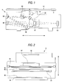
- FIG. 3 shows a schematic structure of an image reader 1 of flat bed type with a moving carriage according to a first embodiment of the invention.
- the cabinet 2 contains a carriage 6 that can be reciprocated by a drive (not shown) in parallel to an original 5 placed on the original document bed 3.
- FIGS. 1 and 2 show the carriage 6 of the image reader 1 of the first embodiment.
- FIG. 1 is a drawing of the carriage viewed from the side with respect to the moving direction of the carriage 6
- FIG. 2 is a drawing of the carriage 6 viewed from the original document bed 3.
- the arrow denotes the moving direction of the carriage 6.
- a light source 61 and a line sensor 62 as a photosensor are mounted on the carriage 6.
- Application light of the light source 61 is reflected on the surface of an original 5 and is reflected by mirrors 63, 64, 65, and 66, then is gathered through a condensing lens 67 on the line sensor 62.
- light from the original 5 is reflected in the order of the mirrors 63, 64, 65, and 66, namely, is reflected by the four mirrors four times for enlarging the optical path length from the original 5 to the condensing lens 67.
- a reflection original 51 of paper, etc. can be used as shown in FIG. 6 and a translucent original 52 of a positive film, a negative film, etc., can be used as shown in FIG. 7.
- the original 5 described throughout the specification contains both the reflection original 51 and the translucent original 52.
- the light source 61 is placed in a direction perpendicular to the moving direction of the carriage 6 and uses a fluorescent lamp, etc.
- a surface light source 68 is placed above the original document bed 3.
- light applied from a fluorescent lamp 681 is reflected on grooves unevenly spaced from each other, made in a light guide plate 682, whereby the light can be applied to the side of the original document bed 3 as uniform light.
- the surface light source 68 has a power receptacle 683 connected to a power supply placed in the cabinet 2 and a switch 684 of the fluorescent lamp 681 is turned on or off through a control section 15 as the user gives a command to a personal computer or the image reader 1.
- a charge-storage photosensor is used as the line sensor 62 and comprises a plurality of elements such as CCD arranged linearly in the direction perpendicular to the move direction of the carriage 6.
- the original document bed 3 is surrounded by an original document guide 4 for regulating a move of the original 5 when the original is read.
- a white reference 31 having a uniform reflection surface of a high reflection factor is placed in the end part of the original document bed 3 in the moving direction of the carriage 6.
- A/D conversion section 11 converts analog data input from the line sensor 62 through an amplifier 10 into a digital signal and passes the digital signal to a shading correction section 12.
- the shading correction section 12 uses read data of the white reference 31 before reading starts and corrects variations in the sensitivity of each element of the line sensor 62 and variations in the light quantity of the light source 61 in the main scanning direction thereof.
- a gamma correction section 13 makes a gamma correction based on a predetermined gamma function and converts the light quantity signal output from the shading correction section 12 into an image signal.
- a miscellaneous correction section 14 executes various types of conversion such as color correction, edge enhancement, and area enlargement/reduction (scaling).
- the control section 15 which is made of a microcomputer consisting of a CPU, RAM, ROM, etc., controls the whole image reader 1 and is connected via an interface 8 to an external image processing system (not shown), such as a personal computer.
- a transparent member 20 is placed between the mirrors 63 and 64 of the carriage 6. It is made of glass, such as silicate glass, and is shaped like a plate and is ground so as to become smooth on the surface and constant in plate thickness.
- the transparent member 20 is placed between the mirrors 63 and 64, whereby the length of the transparent member 20 in a perpendicular direction to the travel direction of light can be lessened as shown in FIG. 1, so that the transparent member 20 can be miniaturized.
- the transparent member 20 is turned like the arrow shown in FIG. 1 by a drive (not shown).
- the transparent member 20 is moved to the position (second predetermined position) indicated by the dashed line in FIG. 1; when the translucent original 52, such as a film, is read as shown in FIG. 7, the transparent member 20 is moved to the position (first predetermined position) indicated by the solid line in FIG. 1. It is moved in accordance with instruction means, such as a switch (not shown), placed on the image reader 1 or as the user gives a command to a personal computer, etc., connected to the image reader 1.
- instruction means such as a switch (not shown) placed on the image reader 1 or as the user gives a command to a personal computer, etc.
- the image reader 1 is controlled by software of a scanner driver, etc., such as TWAIN, installed in the personal computer. If the user selects reading of a translucent original on the TWAIN in the personal computer, the transparent member 20 is inserted into the optical path in response to the translucent original selection command. Even if the translucent original 52 as shown in FIG. 7 is read, it may be placed directly on the original document bed 3 without using the film holder 53. If the film holder 53 is not used, the user can select a noninsertion command of the transparent member 20 on the TWAIN. If the noninsertion command is selected, the transparent member 20 is not inserted into the optical path, or is retracted from the optical path. Next, the transparent member 20 will be discussed in more detail.
- a scanner driver etc.
- silicate glass which is 7.8 mm thick is ground to the thickness 7.5 mm so as to become smooth on the surface for use as the transparent member 20.
- the length in the perpendicular direction to the light travel direction is 12 mm. If the transparent member 20 of a 7.5 mm thickness is used, the focus depth of the condensing lens 67 is ⁇ 0.5 mm, thus, the focus of the condensing lens 67 is obtained in the range of 2.0 mm to 3.0 mm as the distance from the surface of the original document bed 3 on the original 5 side thereof.
- the user connects a personal computer (not shown) to the interface 8 of the image reader 1, places an original 5 on the original document bed 3, and specifies the read range and read resolution from the personal computer, then gives a read execution command.
- the user also specifies whether the original to be read is a reflection or translucent original.
- Software such as TWAIN is started in the personal computer and the user gives a command to the image reader 1 from the software. For example, if the user selects a translucent original, the transparent member 20 is automatically inserted. However, to read a translucent original, the film holder is not always used as described above, thus noninsertion of the transparent member 20 can be selected as required.
- the control section 15 turns on the light source 61 or the surface light source 68 and moves the carriage 6 to the read line positions in sequence at constant speed, whereby charges (signal charges) are accumulated in the line sensor 62 in the amount proportional to the reflection factor (light and shade) or transmission factor of the original 5 at each read line position.
- the charges accumulated in the line sensor 62 are output to the amplifier 10 after the expiration of a predetermined time, and the line sensor 62 is moved to the next read line position.
- an output signal from the amplifier 10 is converted into digital light quantity signal data by the A/D conversion section 11 and the digital data is subjected to various corrections in the shading correction section 12, the gamma correction section 13, and the miscellaneous correction section 14, then is output via the interface 8 to the personal computer, etc.
- the transparent member 20 is provided, that can be inserted into or retracted from the optical path from the surface of the original document bed 3 on the carriage 6 side to the condensing lens 67, whereby the condensing lens 67 can be focused on the reflection original and the translucent original.
- the condensing lens 67 can also be focused on more than one position simply by providing the transparent member 20 that can be inserted into or retracted from the optical path, so that the structure is simple and the manufacturing costs can be reduced.
- a second embodiment of the invention has the same configuration as the first embodiment except that a transparent member has antireflection means, as shown in FIG. 9.
- Nonreflection coatings 71 and 72 as antireflection means are applied to a surface 701 and a rear face 702 of a transparent member 70 with respect to the light travel direction thereof.
- a multilayer film coating as applied to a lens of a camera is used as the nonreflection coating 71, 72.
- the nonreflection coatings 71 and 72 prevent light from an original 5 passing through the transparent member 70 from being reflected on the surface 701 and the rear face 702 of the transparent member 70.
- Light 101 from an original passing through a transparent member 63 is reflected on a surface 631 and a rear face 632 of the transparent member 63 to which a nonreflection coating is not applied with respect to the light travel direction thereof, as shown in FIG. 10.
- Light 102 reflected on the surface of the transparent member 63 scarcely interferes with the light 101 from the original and has a small effect on the reading of the original.
- light 103 reflected on the rear face 632 of the transparent member 63 is further reflected on the inside of the surface 631 of the transparent member 63 and travels toward a photosensor 62.
- the reflected light 103 and light 104 not reflected and passing through the transparent member 63 differ in optical path and differ in incident position on the photosensor 62, as shown in FIG. 10.
- a ghost 105 may appear, interfering with clear reading of the original. This phenomenon occurs noticeably as the transparent member 63 becomes thicker.
- the nonreflection coatings 71 and 72 may be applied to the transparent member 70 as shown in FIG. 9, whereby light is prevented from being reflected on the surface 701 and the rear face 702 of the transparent member 70.
- the nonreflection coatings 71 and 72 are applied to the transparent member 70, whereby the ghost 105, which would otherwise occur because of insertion of the transparent member into the optical path, is prevented. Therefore, the original can be read more clearly.
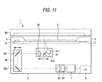
- a third embodiment of the invention will be discussed with reference to FIG. 11. Parts identical with or similar to those in the first and second embodiments previously described are denoted by the same reference numerals in FIG. 11 and will not be discussed again.
- the image reader of flat bed type with a moving carriage incorporating the transparent member of the invention has been described.
- an image reader of flat bed type with moving mirrors incorporating the transparent member of the invention will be discussed.
- An image reader 1 has a first carriage 91 and a second carriage 92 in a cabinet 2.
- the first carriage 91 is provided with a light source 911 for reflection originals, a mirror 912, and a transparent member 20.
- the transparent member described in the first or second embodiment can be applied as the transparent member 20.
- the second carriage 92 is provided with mirrors 921 and 922.
- Light applied from the light source 911 or a surface light source 68 is reflected on an original 5 or passes through the original 5 and is reflected on the mirrors 912, 921, and 922.
- the light reflected on the mirrors 912, 921, and 922 is gathered through a condensing lens 93 on a line sensor 94 and is converted into an electric signal by the line sensor 94.
- the first carriage 91 and the second carriage 92 can be moved separately in the direction indicated by the arrow in FIG. 11.
- the first carriage 91 and the second carriage 92 are moved separately, whereby the distance from the mirror 912 to the mirror 921 and that from the mirror 922 to the condensing lens 93 can be changed whenever necessary.
- the optical path length from the original 5 to the condensing lens 93 is changed, so that it is made possible to focus the condensing lens 93 on the original 5 with high accuracy.
- the first carriage 91 is provided with the transparent member 20.
- the condensing lens 93 can also be focused on the original 5 with high accuracy.
- the image reader of flat bed type with moving mirrors incorporates the transparent member of the invention, whereby if the resolution of the image reader is enhanced to more than the former resolution, for example, to 1600 dpi or more, originals can be read with high accuracy.
- the transparent member made of silicate glass is applied to the image reader of the invention; a transparent resin, glass, etc., having a large refractive index is applied to the invention, whereby the transparent member can be thinned and the carriage can be more miniaturized.
Landscapes
- Engineering & Computer Science (AREA)
- Multimedia (AREA)
- Signal Processing (AREA)
- Facsimile Scanning Arrangements (AREA)
- Facsimile Heads (AREA)
- Optical Systems Of Projection Type Copiers (AREA)
Applications Claiming Priority (6)
| Application Number | Priority Date | Filing Date | Title |
|---|---|---|---|
| JP32681898 | 1998-11-17 | ||
| JP32681898 | 1998-11-17 | ||
| JP9467499 | 1999-04-01 | ||
| JP9467499 | 1999-04-01 | ||
| JP11213637A JP3141375B2 (ja) | 1998-11-17 | 1999-07-28 | 画像読み取り装置および画像読み取り方法 |
| JP21363799 | 1999-07-28 |
Publications (3)
| Publication Number | Publication Date |
|---|---|
| EP1003323A2 true EP1003323A2 (fr) | 2000-05-24 |
| EP1003323A3 EP1003323A3 (fr) | 2002-04-17 |
| EP1003323B1 EP1003323B1 (fr) | 2007-01-10 |
Family
ID=27307611
Family Applications (1)
| Application Number | Title | Priority Date | Filing Date |
|---|---|---|---|
| EP99121979A Expired - Lifetime EP1003323B1 (fr) | 1998-11-17 | 1999-11-10 | Dispositif de lecture d'image et procédé de lecture d'image |
Country Status (4)
| Country | Link |
|---|---|
| US (1) | US6628432B1 (fr) |
| EP (1) | EP1003323B1 (fr) |
| JP (1) | JP3141375B2 (fr) |
| DE (1) | DE69934762T2 (fr) |
Cited By (6)
| Publication number | Priority date | Publication date | Assignee | Title |
|---|---|---|---|---|
| US6906314B2 (en) | 2003-02-20 | 2005-06-14 | Hewlett-Packard Development Company, L.P. | Systems and methods for providing multiple object planes in an optical image scanner |
| US7055743B2 (en) | 2003-02-20 | 2006-06-06 | Hewlett-Packard Development Company, L.P. | End-of-travel focus shift in an optical image scanner |
| US7147158B2 (en) | 2003-02-20 | 2006-12-12 | Hewlett-Packard Development Company, L.P. | Systems and methods for providing multiple object planes in an optical image scanner |
| US7209618B2 (en) | 2003-03-25 | 2007-04-24 | Hewlett-Packard Development Company, L.P. | Scanner transparent media adapter using fiber optic face plate |
| US7225984B2 (en) | 2003-02-20 | 2007-06-05 | Harris Rodney C | Systems and methods for providing multiple object planes in an optical image scanning environment |
| US7251062B2 (en) | 2003-02-20 | 2007-07-31 | Hewlett-Packard Development Company, L.P. | End-of-travel focus shift in an optical image scanner |
Families Citing this family (6)
| Publication number | Priority date | Publication date | Assignee | Title |
|---|---|---|---|---|
| US20020071141A1 (en) * | 2000-06-05 | 2002-06-13 | Fuji Photo Film Co., Ltd. | Image reading device and image reading method |
| TW564631B (en) * | 2002-06-28 | 2003-12-01 | Veutron Corp | Optical path device of curved mirror |
| JP4565541B2 (ja) * | 2003-10-31 | 2010-10-20 | 日本発條株式会社 | 識別媒体および識別対象物品 |
| TW200726201A (en) * | 2005-12-26 | 2007-07-01 | Benq Corp | Image capturing apparatus and focusing method thereof |
| JP5353084B2 (ja) * | 2008-06-20 | 2013-11-27 | 株式会社リコー | 画像読取装置および画像読取装置を備えた画像形成装置 |
| JP5015867B2 (ja) * | 2008-06-20 | 2012-08-29 | 株式会社リコー | 原稿照明装置、画像読取装置および画像形成装置 |
Family Cites Families (13)
| Publication number | Priority date | Publication date | Assignee | Title |
|---|---|---|---|---|
| US4278999A (en) * | 1979-09-12 | 1981-07-14 | The Mead Corporation | Moving image scanner |
| US5140443A (en) | 1989-07-25 | 1992-08-18 | Victor Company Of Japan, Ltd. | Image scanning apparatus |
| JPH065868B2 (ja) | 1990-02-28 | 1994-01-19 | 株式会社ピーエフユー | 原稿読取装置 |
| JPH05122451A (ja) | 1991-10-24 | 1993-05-18 | Seiko Epson Corp | イメージスキヤナ |
| JPH05122442A (ja) | 1991-10-24 | 1993-05-18 | Seiko Epson Corp | イメージスキヤナ |
| JP3006229B2 (ja) | 1991-11-07 | 2000-02-07 | セイコーエプソン株式会社 | スキャナの原稿回収装置 |
| JP3707810B2 (ja) * | 1993-08-26 | 2005-10-19 | ヒューレット・パッカード・カンパニー | スキャナ用アダプタ |
| CH690639A5 (de) * | 1994-11-29 | 2000-11-15 | Zeiss Carl Fa | Vorrichtung zum scannenden Digitalisieren von Bildvorlagen sowie Verfahren zu deren Betrieb. |
| US5574274A (en) | 1995-02-21 | 1996-11-12 | Microtek International, Inc. | Transmissive/reflective optical scanning apparatus |
| US5710643A (en) | 1995-06-29 | 1998-01-20 | Agfa Divisionn, Bayer Corporation | Optical path for a scanning system |
| JP3990472B2 (ja) | 1996-08-19 | 2007-10-10 | 富士フイルム株式会社 | ビーム径制御方法および装置 |
| JP3250967B2 (ja) | 1996-12-25 | 2002-01-28 | マルマス機械株式会社 | コイン式精米装置 |
| US6169611B1 (en) * | 1997-12-24 | 2001-01-02 | Agfa Corporation | Mounting system for a removable media holder in a scanning apparatus |
-
1999
- 1999-07-28 JP JP11213637A patent/JP3141375B2/ja not_active Expired - Fee Related
- 1999-11-02 US US09/432,424 patent/US6628432B1/en not_active Expired - Lifetime
- 1999-11-10 EP EP99121979A patent/EP1003323B1/fr not_active Expired - Lifetime
- 1999-11-10 DE DE69934762T patent/DE69934762T2/de not_active Expired - Lifetime
Cited By (6)
| Publication number | Priority date | Publication date | Assignee | Title |
|---|---|---|---|---|
| US6906314B2 (en) | 2003-02-20 | 2005-06-14 | Hewlett-Packard Development Company, L.P. | Systems and methods for providing multiple object planes in an optical image scanner |
| US7055743B2 (en) | 2003-02-20 | 2006-06-06 | Hewlett-Packard Development Company, L.P. | End-of-travel focus shift in an optical image scanner |
| US7147158B2 (en) | 2003-02-20 | 2006-12-12 | Hewlett-Packard Development Company, L.P. | Systems and methods for providing multiple object planes in an optical image scanner |
| US7225984B2 (en) | 2003-02-20 | 2007-06-05 | Harris Rodney C | Systems and methods for providing multiple object planes in an optical image scanning environment |
| US7251062B2 (en) | 2003-02-20 | 2007-07-31 | Hewlett-Packard Development Company, L.P. | End-of-travel focus shift in an optical image scanner |
| US7209618B2 (en) | 2003-03-25 | 2007-04-24 | Hewlett-Packard Development Company, L.P. | Scanner transparent media adapter using fiber optic face plate |
Also Published As
| Publication number | Publication date |
|---|---|
| DE69934762D1 (de) | 2007-02-22 |
| JP2000349960A (ja) | 2000-12-15 |
| EP1003323B1 (fr) | 2007-01-10 |
| EP1003323A3 (fr) | 2002-04-17 |
| JP3141375B2 (ja) | 2001-03-05 |
| DE69934762T2 (de) | 2007-10-11 |
| US6628432B1 (en) | 2003-09-30 |
Similar Documents
| Publication | Publication Date | Title |
|---|---|---|
| US6628432B1 (en) | Image reader and image reading method | |
| US4863251A (en) | Double gauss lens for a raster input scanner | |
| US6940063B2 (en) | Optical image scanner with variable focus | |
| US6055072A (en) | Image reading apparatus and image reading system | |
| EP0977423B1 (fr) | Dispositif d'analyse d'images avec compensation en raison de changements d'agrandissement | |
| EP0946040A1 (fr) | Dispositif de lecture d'image et procede de mise au point pour ce dispositif | |
| EP0866353A2 (fr) | Lecteur de document et méthode de focalisation | |
| EP0822705A2 (fr) | Appareil et système d'analyse d'images | |
| US6771408B2 (en) | Optical lens device of image scanner | |
| US6555854B2 (en) | Charge coupled device with multi-focus lengths | |
| JP2001084352A (ja) | 画像読取装置 | |
| EP0940968A2 (fr) | Appareil de lecture d'images et procédé de traitement de signaux d'image | |
| US7225984B2 (en) | Systems and methods for providing multiple object planes in an optical image scanning environment | |
| US20040164223A1 (en) | Automatic object plane selection in an optical image scanner | |
| US20040164152A1 (en) | Optical image scanning with user adjustable object plane | |
| JP2003037712A (ja) | 画像読取装置 | |
| JP4089136B2 (ja) | キャリッジおよびその調整方法 | |
| JP3018560B2 (ja) | イメージセンサ | |
| JP2002010002A (ja) | 画像読み取り装置 | |
| JP2002111978A (ja) | 画像読み取り装置 | |
| JP2002006420A (ja) | キャリッジおよびそれを備えた画像読取装置 | |
| JPH06291945A (ja) | 画像読取装置 | |
| JPH04142863A (ja) | 画像読取装置 | |
| JP2004233514A (ja) | 画像読取装置 | |
| JPH11142667A (ja) | 光導波路アレイ基板及びそれから構成されるイメージセンサ |
Legal Events
| Date | Code | Title | Description |
|---|---|---|---|
| PUAI | Public reference made under article 153(3) epc to a published international application that has entered the european phase |
Free format text: ORIGINAL CODE: 0009012 |
|
| AK | Designated contracting states |
Kind code of ref document: A2 Designated state(s): AT BE CH CY DE DK ES FI FR GB GR IE IT LI LU MC NL PT SE |
|
| AX | Request for extension of the european patent |
Free format text: AL;LT;LV;MK;RO;SI |
|
| PUAL | Search report despatched |
Free format text: ORIGINAL CODE: 0009013 |
|
| AK | Designated contracting states |
Kind code of ref document: A3 Designated state(s): AT BE CH CY DE DK ES FI FR GB GR IE IT LI LU MC NL PT SE |
|
| AX | Request for extension of the european patent |
Free format text: AL;LT;LV;MK;RO;SI |
|
| 17P | Request for examination filed |
Effective date: 20020628 |
|
| AKX | Designation fees paid |
Free format text: AT BE CH CY DE DK ES FI FR GB GR IE IT LI LU MC NL PT SE |
|
| 17Q | First examination report despatched |
Effective date: 20050706 |
|
| GRAP | Despatch of communication of intention to grant a patent |
Free format text: ORIGINAL CODE: EPIDOSNIGR1 |
|
| GRAS | Grant fee paid |
Free format text: ORIGINAL CODE: EPIDOSNIGR3 |
|
| GRAA | (expected) grant |
Free format text: ORIGINAL CODE: 0009210 |
|
| AK | Designated contracting states |
Kind code of ref document: B1 Designated state(s): AT BE CH CY DE DK ES FI FR GB GR IE IT LI LU MC NL PT SE |
|
| PG25 | Lapsed in a contracting state [announced via postgrant information from national office to epo] |
Ref country code: NL Free format text: LAPSE BECAUSE OF FAILURE TO SUBMIT A TRANSLATION OF THE DESCRIPTION OR TO PAY THE FEE WITHIN THE PRESCRIBED TIME-LIMIT Effective date: 20070110 Ref country code: LI Free format text: LAPSE BECAUSE OF FAILURE TO SUBMIT A TRANSLATION OF THE DESCRIPTION OR TO PAY THE FEE WITHIN THE PRESCRIBED TIME-LIMIT Effective date: 20070110 Ref country code: FI Free format text: LAPSE BECAUSE OF FAILURE TO SUBMIT A TRANSLATION OF THE DESCRIPTION OR TO PAY THE FEE WITHIN THE PRESCRIBED TIME-LIMIT Effective date: 20070110 Ref country code: DK Free format text: LAPSE BECAUSE OF FAILURE TO SUBMIT A TRANSLATION OF THE DESCRIPTION OR TO PAY THE FEE WITHIN THE PRESCRIBED TIME-LIMIT Effective date: 20070110 Ref country code: CH Free format text: LAPSE BECAUSE OF FAILURE TO SUBMIT A TRANSLATION OF THE DESCRIPTION OR TO PAY THE FEE WITHIN THE PRESCRIBED TIME-LIMIT Effective date: 20070110 Ref country code: AT Free format text: LAPSE BECAUSE OF FAILURE TO SUBMIT A TRANSLATION OF THE DESCRIPTION OR TO PAY THE FEE WITHIN THE PRESCRIBED TIME-LIMIT Effective date: 20070110 |
|
| REG | Reference to a national code |
Ref country code: GB Ref legal event code: FG4D |
|
| REG | Reference to a national code |
Ref country code: IE Ref legal event code: FG4D |
|
| REF | Corresponds to: |
Ref document number: 69934762 Country of ref document: DE Date of ref document: 20070222 Kind code of ref document: P |
|
| PG25 | Lapsed in a contracting state [announced via postgrant information from national office to epo] |
Ref country code: SE Free format text: LAPSE BECAUSE OF FAILURE TO SUBMIT A TRANSLATION OF THE DESCRIPTION OR TO PAY THE FEE WITHIN THE PRESCRIBED TIME-LIMIT Effective date: 20070410 |
|
| PG25 | Lapsed in a contracting state [announced via postgrant information from national office to epo] |
Ref country code: ES Free format text: LAPSE BECAUSE OF FAILURE TO SUBMIT A TRANSLATION OF THE DESCRIPTION OR TO PAY THE FEE WITHIN THE PRESCRIBED TIME-LIMIT Effective date: 20070421 |
|
| PG25 | Lapsed in a contracting state [announced via postgrant information from national office to epo] |
Ref country code: PT Free format text: LAPSE BECAUSE OF FAILURE TO SUBMIT A TRANSLATION OF THE DESCRIPTION OR TO PAY THE FEE WITHIN THE PRESCRIBED TIME-LIMIT Effective date: 20070611 |
|
| NLV1 | Nl: lapsed or annulled due to failure to fulfill the requirements of art. 29p and 29m of the patents act | ||
| ET | Fr: translation filed | ||
| REG | Reference to a national code |
Ref country code: CH Ref legal event code: PL |
|
| PLBE | No opposition filed within time limit |
Free format text: ORIGINAL CODE: 0009261 |
|
| STAA | Information on the status of an ep patent application or granted ep patent |
Free format text: STATUS: NO OPPOSITION FILED WITHIN TIME LIMIT |
|
| 26N | No opposition filed |
Effective date: 20071011 |
|
| PG25 | Lapsed in a contracting state [announced via postgrant information from national office to epo] |
Ref country code: BE Free format text: LAPSE BECAUSE OF FAILURE TO SUBMIT A TRANSLATION OF THE DESCRIPTION OR TO PAY THE FEE WITHIN THE PRESCRIBED TIME-LIMIT Effective date: 20070110 |
|
| PG25 | Lapsed in a contracting state [announced via postgrant information from national office to epo] |
Ref country code: IT Free format text: LAPSE BECAUSE OF FAILURE TO SUBMIT A TRANSLATION OF THE DESCRIPTION OR TO PAY THE FEE WITHIN THE PRESCRIBED TIME-LIMIT Effective date: 20070110 Ref country code: GR Free format text: LAPSE BECAUSE OF FAILURE TO SUBMIT A TRANSLATION OF THE DESCRIPTION OR TO PAY THE FEE WITHIN THE PRESCRIBED TIME-LIMIT Effective date: 20070411 |
|
| PG25 | Lapsed in a contracting state [announced via postgrant information from national office to epo] |
Ref country code: MC Free format text: LAPSE BECAUSE OF NON-PAYMENT OF DUE FEES Effective date: 20071130 |
|
| PG25 | Lapsed in a contracting state [announced via postgrant information from national office to epo] |
Ref country code: IE Free format text: LAPSE BECAUSE OF NON-PAYMENT OF DUE FEES Effective date: 20071112 |
|
| PG25 | Lapsed in a contracting state [announced via postgrant information from national office to epo] |
Ref country code: CY Free format text: LAPSE BECAUSE OF FAILURE TO SUBMIT A TRANSLATION OF THE DESCRIPTION OR TO PAY THE FEE WITHIN THE PRESCRIBED TIME-LIMIT Effective date: 20070110 |
|
| PG25 | Lapsed in a contracting state [announced via postgrant information from national office to epo] |
Ref country code: LU Free format text: LAPSE BECAUSE OF NON-PAYMENT OF DUE FEES Effective date: 20071110 |
|
| PGFP | Annual fee paid to national office [announced via postgrant information from national office to epo] |
Ref country code: DE Payment date: 20121107 Year of fee payment: 14 Ref country code: FR Payment date: 20121130 Year of fee payment: 14 |
|
| PGFP | Annual fee paid to national office [announced via postgrant information from national office to epo] |
Ref country code: GB Payment date: 20121107 Year of fee payment: 14 |
|
| GBPC | Gb: european patent ceased through non-payment of renewal fee |
Effective date: 20131110 |
|
| REG | Reference to a national code |
Ref country code: FR Ref legal event code: ST Effective date: 20140731 |
|
| PG25 | Lapsed in a contracting state [announced via postgrant information from national office to epo] |
Ref country code: DE Free format text: LAPSE BECAUSE OF NON-PAYMENT OF DUE FEES Effective date: 20140603 |
|
| REG | Reference to a national code |
Ref country code: DE Ref legal event code: R119 Ref document number: 69934762 Country of ref document: DE Effective date: 20140603 |
|
| PG25 | Lapsed in a contracting state [announced via postgrant information from national office to epo] |
Ref country code: FR Free format text: LAPSE BECAUSE OF NON-PAYMENT OF DUE FEES Effective date: 20131202 Ref country code: GB Free format text: LAPSE BECAUSE OF NON-PAYMENT OF DUE FEES Effective date: 20131110 |