EP1003347A2 - Réseau comprenant plusieurs utilisateurs et procédé pour le fonctionnement de ce réseau - Google Patents
Réseau comprenant plusieurs utilisateurs et procédé pour le fonctionnement de ce réseau Download PDFInfo
- Publication number
- EP1003347A2 EP1003347A2 EP99114720A EP99114720A EP1003347A2 EP 1003347 A2 EP1003347 A2 EP 1003347A2 EP 99114720 A EP99114720 A EP 99114720A EP 99114720 A EP99114720 A EP 99114720A EP 1003347 A2 EP1003347 A2 EP 1003347A2
- Authority
- EP
- European Patent Office
- Prior art keywords
- atm
- interfaces
- network
- terminals
- information
- Prior art date
- Legal status (The legal status is an assumption and is not a legal conclusion. Google has not performed a legal analysis and makes no representation as to the accuracy of the status listed.)
- Withdrawn
Links
Images


Classifications
-
- H—ELECTRICITY
- H04—ELECTRIC COMMUNICATION TECHNIQUE
- H04Q—SELECTING
- H04Q11/00—Selecting arrangements for multiplex systems
- H04Q11/04—Selecting arrangements for multiplex systems for time-division multiplexing
- H04Q11/0428—Integrated services digital network, i.e. systems for transmission of different types of digitised signals, e.g. speech, data, telecentral, television signals
- H04Q11/0478—Provisions for broadband connections
-
- H—ELECTRICITY
- H04—ELECTRIC COMMUNICATION TECHNIQUE
- H04L—TRANSMISSION OF DIGITAL INFORMATION, e.g. TELEGRAPHIC COMMUNICATION
- H04L41/00—Arrangements for maintenance, administration or management of data switching networks, e.g. of packet switching networks
- H04L41/08—Configuration management of networks or network elements
- H04L41/0895—Configuration of virtualised networks or elements, e.g. virtualised network function or OpenFlow elements
-
- H—ELECTRICITY
- H04—ELECTRIC COMMUNICATION TECHNIQUE
- H04L—TRANSMISSION OF DIGITAL INFORMATION, e.g. TELEGRAPHIC COMMUNICATION
- H04L12/00—Data switching networks
- H04L12/54—Store-and-forward switching systems
- H04L12/56—Packet switching systems
- H04L12/5601—Transfer mode dependent, e.g. ATM
- H04L2012/5614—User Network Interface
- H04L2012/5616—Terminal equipment, e.g. codecs, synch.
-
- H—ELECTRICITY
- H04—ELECTRIC COMMUNICATION TECHNIQUE
- H04L—TRANSMISSION OF DIGITAL INFORMATION, e.g. TELEGRAPHIC COMMUNICATION
- H04L12/00—Data switching networks
- H04L12/54—Store-and-forward switching systems
- H04L12/56—Packet switching systems
- H04L12/5601—Transfer mode dependent, e.g. ATM
- H04L2012/5625—Operations, administration and maintenance [OAM]
- H04L2012/5626—Network management, e.g. Intelligent nets
-
- H—ELECTRICITY
- H04—ELECTRIC COMMUNICATION TECHNIQUE
- H04L—TRANSMISSION OF DIGITAL INFORMATION, e.g. TELEGRAPHIC COMMUNICATION
- H04L12/00—Data switching networks
- H04L12/54—Store-and-forward switching systems
- H04L12/56—Packet switching systems
- H04L12/5601—Transfer mode dependent, e.g. ATM
- H04L2012/5629—Admission control
- H04L2012/563—Signalling, e.g. protocols, reference model
Definitions
- the present invention relates to a network of several end devices, in particular computers, which with each other via a user network interface (UNI) - Interface for each end device and at least one Asynchronous transfer mode (ATM) switch are connected, being on at least one of the terminals Information on configuring, monitoring and operating the Interfaces are stored and the terminals are ATM connections have and with each other via virtual ATM channels Exchange data.
- UNI user network interface
- ATM Asynchronous transfer mode
- the invention also relates to a method of operation a network of several end devices, in particular of Computers that interact with each other via a user network interface (UNI) interface for each end device and at least one asynchronous transfer mode (ATM) switch are connected, with at least one of the end devices information about the configuration, Monitoring and operation of the interfaces are filed and the terminals having ATM connections and exchange data with each other via virtual ATM channels.
- UNI user network interface
- ATM asynchronous transfer mode
- Such networks are known from the prior art Networking end devices, in particular computers, and for data transmission from one terminal to another Terminal known within the network. With these The data is networked according to the asynchronous transfer mode (ATM) method transmitted.
- ATM asynchronous transfer mode
- This Transmission method allows a high transmission rate of currently up to 625 Mbit / s per connection and can be used for a certain quality of service for each data transmission process to guarantee.
- To determine the quality of service everyone Data transfer process a certain class of service assigned, which decides whether the data of a Data transfer process preferred or only then be transmitted when on the ATM connection Transmission capacities are free.
- the first class of service (constant bit rate, CBR) is used, for example. for the transmission of voice data.
- the dates of the first Class are preferred and come with one guaranteed short time delay at the receiving Terminal. This is ensured by a central control unit, the so-called ATM switch that the entire Controls data transmission in the ATM network centrally.
- the second class is divided into two subclasses, namely in the so-called Variable Bit Rate - Real Time (VBR-rt) class For example, for the transmission of video data and in the so-called Variable Bit Rate - Non Real Time (VBR-nrt) class, e.g. for the transmission of sensitive text messages.
- VBR-rt Variable Bit Rate - Real Time
- VBR-nrt Variable Bit Rate - Non Real Time
- the third Class (Available Bitrate, ABR) is used to transmit Text messages without bandwidth guarantees with minimization data loss due to transmitter-receiver feedback.
- UBR Unspecified Bit Rate
- the terminals that are networked together in the ATM network are, have ATM connections with which they are via ATM channels are connected to the ATM switch.
- Per ATM network is usually an ATM switch to disposal.
- Between the ATM switch and the Terminal devices is one in the ATM channels Interface arranged.
- the interfaces are usually as a user network interface (UNI) - Interfaces trained.
- the information on Configure, monitor and operate the UNI interfaces are, for example, in a database on the filed at least one terminal. Such a database is the most comfortable alternative, basically however, the information can also be saved in a file be filed.
- the database is usually considered one Management information base (MIB) database trained. Those stored in the at least one terminal Information is provided as an integrated local management interface (ILMI) information.
- MIB Management information base
- ILMI integrated local management interface
- the ILMI information include, for example, information on Identification of the virtual ATM channels or parameters of the Interfaces (address, transmission rate, etc.).
- Identification of the virtual ATM channels is a so-called Virtual Path Connection Identifier (VPCI) numbering or uses Virtual Path Identifier (VPI) numbering.
- VPCI Virtual Path Connection Identifier
- VPN Virtual Path Identifier
- means are on all devices to control the connection establishment and disconnection between the end devices and for configuration, monitoring and operation of the UNI interfaces.
- the means are usually designed as driver software.
- This driver software occupies a large amount Storage space in the end devices. It is relatively expensive and requires intensive maintenance in order to always run smoothly Process of data transmission over the ATM network ensure.
- the object of the present invention is therefore in that a network of the type mentioned above to design and develop that the Storage space required in the end devices for this driver software and the effort for installation and maintenance of the Driver software can be reduced.
- the invention suggests of the network of the type mentioned above that only on some of the end devices, the so-called proxy agents, means to control the connection establishment and disconnection between the end devices and for configuration, monitoring and operation of the interfaces are stored.
- the means are preferably based on driver software filed with the proxy agent. According to the invention is recognized been that the storage space required in the terminals for the driver software for controlling the connection establishment and Disconnection between the end devices and Configure, monitor and operate the interfaces and the effort to install and maintain the driver software can be reduced in a simple manner that the software can only be used on selected devices, the so-called proxy agent.
- the ATM network is designed such that the proxy agents establish the connection and Disconnection between all end devices in the network can control. To do this, the proxy agents have to deal with them assigned devices can communicate. This can happen over a connection in the ATM network. she then runs over an ATM virtual channel to the ATM switch and from there over another virtual ATM channel to the terminal. Both virtual ATM channels form a virtual ATM connection channel.
- the Communication can, for example, be based on a Communication layer of the ATM network, the so-called ATM adaptation Layer 5, or if a local area network (LAN) exists - which is because of the wide distribution of LANs will often be the case - this can Communication takes place over the LAN. This allows the Interfaces between all end devices and the ATM switching switches the network through the proxy agents can be controlled.
- the interfaces are preferred as user network interface (UNI) interfaces educated.
- the network according to the invention has the advantage that the Driver software only on the proxy agent installed, maintained and operated. Thereby can save valuable storage space on all other end devices be saved. It also makes the software related time and cost of installation, Maintenance and operation significantly reduced.
- the information to configure Monitoring and operation of the interfaces for example, in one Database stored on the at least one terminal.
- a Database is the most convenient alternative in principle, however, the information can also be in a File stored.
- the database is preferably as a management information base (MIB) database educated.
- MIB management information base
- the one Proxy agent can control the requirements of the Connection establishment and disconnection between the Fully meet terminal devices in the ATM network. On the a proxy agent can connect and Connection clearing controlled by all interfaces become.
- ILMI Integrated Local Management Interface
- the channels to transmit the information is then referred to as ILMI channels.
- the ILMI channels are registration channels through which new ones Terminal devices are registered.
- ILMI channels also fault messages and Parameter changes of a UNI interface transmitted become. The exchange takes place via the signaling channel of messages for setting up and clearing down connections, e.g. SETUP, CALL PROCEEDING, CONNECT.
- the signaling channels and the channels for transmitting the Information on configuring, monitoring and operating the Interfaces are preferably permanent virtual ones Connections (e.g. as a so-called permanent virtual channel Connection, PVCC).
- the interfaces advantageously have several Layers of the broadband ISDN reference model, the Interfaces between the terminals and the ATM switching switches one physical layer and one Have ATM layer, and the interfaces between the Proxy agents and the ATM switch switches additionally an ATM adaptation layer, a service-specific connection-oriented protocol (SSCOP) layer, a service-specific coordination function (SSCF) layer and one Layer to configure, monitor and operate the Have interfaces.
- SSCOP service-specific connection-oriented protocol
- SSCF service-specific coordination function
- VPI virtual path identifier
- VCI Virtual Channel Identifier
- connection establishment and disconnection however how not all terminals in the present invention itself, but by a few, possibly even only controlled by a proxy agent, that is enough VPI / VCI numbering no longer works because of the virtual ATM channels the end devices cannot be clearly identified.
- the virtual ATM channels between the terminals and the ATM switch, the signaling channels and the Channels for transmitting the information for configuration, Monitoring and operation of the interfaces one by all Interfaces have consecutive numbering that the Proxy agents and the ATM switch switches is known.
- the numbering is also called the virtual path connection identifier (VPCI) numbering.
- the proxy agent shares the VPCI number of one with the ATM switch desired virtual ATM connection channel with.
- the ATM switch then converts it to the corresponding one VPI / VCI number of the corresponding terminal and speaks so the corresponding virtual ATM channel of the corresponding terminal.
- Inquiries are also processed specific terminal with a specific VPI / VCI number from the ATM switch to the corresponding VPCI number converted to the proxy agent is forwarded.
- the proxy agents advantageously have access to the Information on configuring, monitoring and operating the Interfaces.
- the configuration information, Monitoring and operation of the interfaces are also considered ILMI information is referred to and is in a database, preferably an MIB database, or otherwise trained MIB filed.
- the ILMI information is in one or more MIBs on one or more end devices filed. Since the proxy agent also represents an end device, they can also be stored there.
- the ILMI information include, for example, the values of the VPI / VCI numbers of one Interface or other parameters of the interface (Name, transfer rate, etc.).
- the terminals are preferably via a local area network (LAN), especially over an Ethernet network connected. Depending on the requirements for data transmission can then either the data over the ATM network or transmitted over the Ethernet network.
- LAN local area network
- Another object of the present invention is in that a method of the type mentioned to design and develop that the Storage space required in the end devices for the driver software and the effort for installation and maintenance of the Driver software can be reduced.
- the invention proposes that the connection establishment and the disconnection between the End devices and configuring, monitoring and the Operation of the interfaces only from some of the end devices, the so-called proxy agent.
- the Proxy agents preferably stored driver software.
- the proxy agents monitor the communication from one Terminal to another terminal of the ATM network and configure, monitor and control the operation of the Interfaces.
- the interfaces are preferably as User network interface (UNI) interfaces trained.
- the interfaces are preferably in a database, preferably in a management information base (MIB) database, stored on the at least one terminal.
- MIB management information base
- a The database is the most convenient alternative To store information, in principle the However, information can also be stored in a file.
- switch switches between the ATM and the proxy agent for everyone in that Network operated interface a signaling channel and a channel for transmitting the information to the Configure, monitor and operate the interfaces as permanent virtual connections (e.g. as so-called PVCCs).
- the signaling and switching functions at Connection establishment and disconnection from and to the Terminal devices executed by the responsible proxy agents.
- the ATM addresses of a proxy agent assigned end devices by the proxy agent the corresponding channels for transmitting the information for configuring, monitoring and operating the Interfaces registered.
- the ATM addresses can also be registered via this additional network.
- the Registration of the ATM addresses is done when the terminal puts its ATM connection into operation again or if it is off other reasons, the ATM address of one of the terminals needed. This can happen after a crash of the end device or then be the case if the terminal in the ATM network is newly integrated. This can also be the case if the network administrator assigns a terminal a new ATM address assign or change an existing one.
- the ATM address registration is different from that of ATM networks according to the state of the art not the respective End devices, but only the proxy agent.
- the settings on the ATM connections are advantageous of the end devices from the responsible proxy agents prompted.
- the setting will be initiated if by the ATM switch switch receive appropriate commands or the status of the ATM connections from the responsible proxy agent is monitored.
- the commands become from the ATM switch to the proxy agents over the channels assigned to the ATM connections to Transfer the information to configure, monitor and operation of the UNI interfaces.
- a Changing the settings will be the ATM switch communicated.
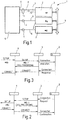
- the Network 1 has a total of three terminals 2, of which one is designed as a proxy agent 3, one with the other via a user network interface (UNI) interface 4 for each terminal 2 and an asynchronous transfer mode (ATM) switch 5 are connected.
- a proxy agent 3 In one of the Terminal devices 2, for example in the proxy agent 3, are integrated local management interfaces (ILMI) information in one Management information base (MIB) database filed.
- the ILMI information is used for configuration, monitoring and to operate the UNI interfaces 4 and include, for example Values of a VPI / VCI numbering, information on the Identification of a virtual ATM channel or parameter the UNI interfaces 4 (address (@A, @B), Transmission rate, etc.).
- the proxy agent 3 has access to the ILMI information in the MIB database. To this The proxy agent 3 can set up the connection and Control disconnection between two terminals 2 and control Configure and monitor UNI interfaces 4 and their Control operations.
- the terminals 2 have ATM connections to one another Exchange data via virtual ATM connection channels can.
- the ATM connection channels consist of several ATM channels 6 and 6 can be used as permanent virtual Connections or as mediated virtual connections (Switched Virtual Channel Connection, SVCC) his.
- the signaling channels 7 and the ILMI channels 8 are designed as permanent virtual connections.
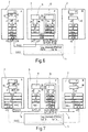
- the signaling channel 7 is used to exchange messages for setting up and clearing down connections, for example SETUP, CALL PROCEEDING, CONNECT signals (see FIGS. 2 and 3).
- the ILMI channels 8 are registration channels via which new terminals 2 are registered.
- fault messages and parameter changes of a UNI interface 4 can also be transmitted via the ILMI channels 8.
- the virtual ATM channels 6 between the terminals 2 and the ATM switch 5 have one through all UNI interfaces 4 universal virtual path connection identifiers (VPCI) numbering.
- the VPCI numbering of proxy agent 3 goes from 0 to a, the VPCI numbering of terminal A then goes from a + 1 to b and that of Terminal B from b + 1 to c. So there is one Consistent VPCI numbering from 0 to c.
- the proxy agent 3 and the ATM switch 5 is this VPCI numbering known.
- the proxy agent 3 can by means of VPCI numbering every desired ATM channel 6 one address any end device 2. For this, the corresponding VPCI number over an ATM channel 6 from that Proxy agent 3 transmitted to the ATM switch 5.
- the ATM switch 5 then converts the VPCI number into a corresponding VPI number of the corresponding Terminal 2 um.
- the terminals 2 can also still with each other via a local area network (LAN) 9 be connected. Depending on the requirements of one Data transmission can transfer data over the ATM network 1 or are transmitted between the terminals 2 via the LAN 9.
- LAN local area network
- Connection request (ConnectionRequest) from terminal A.
- the proxy agent 3 transmitted.
- This connection request takes place via a permanent, specially set up for this purpose virtual connection between the terminal A and the proxy agent 3.
- This connection serves the exchange of control and Status messages between proxy agent 3 and one of terminals 2, in the present case terminal A. If one LAN 9 exists, it can alternatively be used for this purpose become.
- the proxy agent 3 then sends over that of the UNI interface 4 assigned to terminal A.
- Signaling channel 7 a SETUP (@B, ...) message to the ATM switch 5.
- the SETUP message may contain. a.
- Terminal B Information about who the terminal A is connected to wishes (terminal B, address @B) which quality of service which which Traffic parameters (maximum / average bandwidth, This class (CBR, VBR-rt, VBR-nrt, ABR, UBR)) and which Connection configuration (point-to-point or point-to-multipoint) it is asked for.
- the ATM switch 5 sends the SETUP message via the UNI interface 4 the signaling channel 7 assigned to the terminal B again back to the proxy agent 3 (see FIG. 3).
- the proxy agent 3 then notifies terminal B of a specially for this established permanent virtual connection between the Terminal B and the proxy agent 3 by means of a ConnectionIndication signal the connection request from Terminal A with.
- the ATM switch is 5 from FIG. 2 is identical to the ATM switch 5 from FIG. 3.
- the SETUP message from the first ATM switch 5 (from Fig. 2) via a further signaling channel to the second ATM switch 5 (from FIG. 3) transmitted become.
- the interface between the ATM switch switches 5 could then, for example, as a Private Network Network Interface (PNNI) with the associated signaling.
- PNNI Private Network Network Interface
- the ATM switching switch shares the CALL PROCEEDING signal 5 the proxy agent P with that the Connection is established, but not yet established has come. It is assigned to the terminal A Signaling channel 7 sent. In the concrete Exemplary embodiment means that the SETUP message from has been forwarded to the ATM switch 5.
- the CALL PROCEEDING signal is also sent by the proxy agent 3 the signaling channel 7 assigned to the terminal B. sent the ATM switch 5 to indicate that the connection is progressing.
- the receiving terminal B receives the connection request from Terminal A accepts, it shares this with the proxy agent 3 by means of a connection response signal via a dedicated permanent virtual connection with.
- the proxy agent 3 now shares the ATM switch 5 by means of a CONNECT signal via the terminal B assigned signaling channel 7 with that requested connection has been established.
- the ATM switch 5 in turn transmits via the Terminal A assigned signaling channel 7 the CONNECT signal again to the proxy agent 3. This tells the sending terminal A then by means of a ConnectionConfirmation signal the creation of the Connection with. Now the data transfer from the end device A to terminal B.
- TCP Transmission Control Protocol
- ISDN Integrated Services Digital Network
- service interfaces are e.g. Common ISDN Application Programming Interface (CAPI), Telephone Application programming interface (TAPI) from the company Microsoft or Telephone Service Application Programming Interface (TSAPI) from Novell.
- CAI Common ISDN Application Programming Interface
- TAPI Telephone Application programming interface
- TSAPI Telephone Service Application Programming Interface
- the swap Terminals A and B and the proxy agent P control and Status information via so-called permanent virtual channel Connections (PVCCs) that are made manually in the end devices 2 and the ATM switching switch 5 during initial commissioning of these terminals 2 can be set up.
- PVCCs permanent virtual channel Connections
- CAPI * 10 extended CAPI service
- CAPI * 10 extended CAPI service
- the broadband ISDN i.e. ATM
- transport protocols such as TCP or user Includes Data Protocol (UDP).
- UDP User Data Protocol
- the CAPI * service 10 can work in a distributed manner. So he has Representatives on computers that do not have software for Have control of connection establishment and disconnection.
- the representatives accept the service requests and delegate it to a CAPI * proxy 11 who is direct to the connection control software (Call Control) 12 with a corresponding connection request applies.
- the CAPI * proxy 11 reports the fulfillment and the result of the Connection washing to the delegating CAPI * service 10 back.
- the application X calls at local CAPI * service 10 on the terminal A an ATM connection for the application Y (13; the reference symbols for Signals are given in parentheses below).
- the Request (13) is forwarded to the CAPI * service (14), which runs on the computer of the proxy agent P, here referred to as CAPI * proxy 11.
- CAPI * proxy 11 This is addressed to the Call control 12 with the order to establish an ATM connection (so-called Switched Virtual Circuit Connection, SVCC) between the Set up terminal A and terminal B (15).
- SVCC Switched Virtual Circuit Connection
- the application X orders the CAPI * 10, one certain amount of data about the ATM connection just established transferred to application Y (19).
- the CAPI * 10 ensures that the data over the ATM connection (SVCC) transmitted (20) by the CAPI * service 10 on the Receive terminal B and hand it over to application Y. be (22).
- TCP For internal communication between the instances of the distributed CAPI * service, TCP is used.
- the connection request (22) of the application X is from the local CAPI * 10 via a local TCP protocol stack (23) and a specially in the ATM network for the control and Status communication established permanent virtual Permanent Virtual Channel Connection (PVCC) transferred between the terminal A and the proxy agent P. (24).
- the local TCP protocol stack consists of the Communication protocols TCP, an Internet protocol (IP), a Logical Link Control (LLC) and an ATM Adaptation Layer Number 5 (AAL5).
- the connection request (24) is from a local TCP protocol stack of the proxy agent P and transferred to the CAPI * proxy 11 passed on (25). This asks the call control 12 (26), an ATM connection between the terminal A and the Set up terminal B.
- the Call Control 12 is commissioned to do this a UNI signaling stack (27), such a connection build up.
- the UNI signaling stack consists of UNI 4.0 Signaling, service-specific coordination function (SSCF), Service-Specific Connection-Oriented Protocol (SSCOP) and AAL5.
- the UNI signaling stack sends via that for terminal A as PVCC established signaling channel a SETUP message (28) to the ATM switch 5 and receives from it a CALL PROCEEDING message (29). Then receives the UNI signaling stack via the for the terminal B a SETUP message set up as a PVCC signaling channel (30) from the ATM switch 5, processes it, sends a CALL PROCEEDING message (31) and then a CONNECT message (32) back.
- the ATM switch 5 passes the CONNECT message (33) the signaling channel set up for terminal A. the UNI signaling stack in the proxy agent P.
- Now application X starts its data transfer via the newly built SVCC. It turns to the local CAPI * 10 (40), this to the local TCP protocol stack (41) who sent the data via the SVCC to Terminal B transmits (42). There they are from the TCP protocol stack of the terminal B and transferred to the local CAPI * 10 (43), who eventually sent it to the Application Y passes on (44).
- the ATM switching switch connects to the connected terminals 2 5 ATM addresses as part of their commissioning assigned for registration. Can later additional addresses can of course also be registered.
- the management software in the proxy agent P When commissioning terminal A sends a Interface controller 45 to a corresponding signal (46) the management software in the proxy agent P.
- Der Interface controller 45 is specialized as a small one Program trained in the local ATM driver software.
- the signal (46) is preferably transmitted using the AAL5 sent to the control and status PVCC (47).
- Proxy agent P receives the signal (46) from a Monitoring program (monitoring) 48 received (49) and processed.
- a message is sent to a Address registration program 50 sent (51), and by this becomes a so-called address registration procedure started.
- the ATM switching switch 5 also transmits the proxy agent P.
- SNMP Simple Network Management Protocol
- AAL5 AAL5
- ILMI channel 53
- the Address registration program in the proxy agent P inserts its MAC address, stores the ATM address thus formed in the ILMI MIB (56) intended for terminal A and also notifies the ATM switch (57).
Landscapes
- Engineering & Computer Science (AREA)
- Computer Networks & Wireless Communication (AREA)
- Signal Processing (AREA)
- Data Exchanges In Wide-Area Networks (AREA)
Applications Claiming Priority (2)
| Application Number | Priority Date | Filing Date | Title |
|---|---|---|---|
| DE19848359 | 1998-10-21 | ||
| DE19848359A DE19848359A1 (de) | 1998-10-21 | 1998-10-21 | Netzwerk von mehreren Endgeräten und Verfahren zum Betrieb eines Netzwerks von mehreren Endgeräten |
Publications (2)
| Publication Number | Publication Date |
|---|---|
| EP1003347A2 true EP1003347A2 (fr) | 2000-05-24 |
| EP1003347A3 EP1003347A3 (fr) | 2001-10-24 |
Family
ID=7885077
Family Applications (1)
| Application Number | Title | Priority Date | Filing Date |
|---|---|---|---|
| EP99114720A Withdrawn EP1003347A3 (fr) | 1998-10-21 | 1999-07-28 | Réseau comprenant plusieurs utilisateurs et procédé pour le fonctionnement de ce réseau |
Country Status (2)
| Country | Link |
|---|---|
| EP (1) | EP1003347A3 (fr) |
| DE (1) | DE19848359A1 (fr) |
Families Citing this family (1)
| Publication number | Priority date | Publication date | Assignee | Title |
|---|---|---|---|---|
| DE10257450A1 (de) * | 2002-12-09 | 2004-07-15 | Siemens Ag | Verfahren zur Überwachung einer Anwendung in einem Netzwerk sowie Netzwerk zur Durchführung des Verfahrens |
Family Cites Families (3)
| Publication number | Priority date | Publication date | Assignee | Title |
|---|---|---|---|---|
| US5485455A (en) * | 1994-01-28 | 1996-01-16 | Cabletron Systems, Inc. | Network having secure fast packet switching and guaranteed quality of service |
| US5978376A (en) * | 1997-01-23 | 1999-11-02 | Nortel Networks Corporation | Providing access to a distributed data processing system |
| US6111858A (en) * | 1997-02-18 | 2000-08-29 | Virata Limited | Proxy-controlled ATM subnetwork |
-
1998
- 1998-10-21 DE DE19848359A patent/DE19848359A1/de not_active Withdrawn
-
1999
- 1999-07-28 EP EP99114720A patent/EP1003347A3/fr not_active Withdrawn
Also Published As
| Publication number | Publication date |
|---|---|
| DE19848359A1 (de) | 2000-04-27 |
| EP1003347A3 (fr) | 2001-10-24 |
Similar Documents
| Publication | Publication Date | Title |
|---|---|---|
| DE69325203T2 (de) | Verfahren und Vorrichtung für das gemeinsame Nutzen eines Telekommunikationskanals | |
| EP2055112B1 (fr) | Réseau de communication avec commande de commutation de circuits et de paquets | |
| DE10085104B4 (de) | Verfahren und Anordnung in einem Telekommunikationssystem | |
| WO2002065725A2 (fr) | Procede et dispositif pour determiner l'adresse virtuelle d'un terminal | |
| DE69928251T2 (de) | Datennetzkommunikationen | |
| DE10063082A1 (de) | Vorrichtung und Verfahren zum paketbasierten Anschluss von klassischen ISDN/PSTN-Teilnehmern an ein Vermittlungssystem | |
| EP1566018B1 (fr) | Procede de configuration automatique de liaisons de communication entre des unites de communication disposees dans un reseau de communication par paquets | |
| DE60032096T2 (de) | Mehrkanal- Kommunikationssteuerungssystem und -verfahren | |
| DE29517800U1 (de) | ATM-Kommunikationsnetz mit netzinterner Konfiguration eines zusätzlichen ATM-Vermittlungsknotens | |
| EP1003347A2 (fr) | Réseau comprenant plusieurs utilisateurs et procédé pour le fonctionnement de ce réseau | |
| DE19927037B4 (de) | Substitution-Ruf-Steuersystem in einem ATM-Kommunikationsnetzwerk | |
| EP1854267A1 (fr) | Procede pour etablir une liaison de communication dans au moins un reseau de communication | |
| EP1305957B1 (fr) | Systeme permettant de connecter un dispositif de telecommunication a un reseau de communication a commutation de paquets | |
| EP1707018B1 (fr) | Unite d'adaptateur | |
| DE69938391T2 (de) | Telefonvermittlungsstelle mit integrierten internetzugriffservern | |
| DE10063081A1 (de) | Verfahren zum paketbasierten Anschluss von klassischen ISDN/PSTN-Teilnehmern an ein Vermittlungssystem | |
| EP1099326A2 (fr) | Procede pour etablir une liaison entre des terminaux et des modems externes | |
| DE69927588T2 (de) | Mehrfachvermittlungszentrale-datennetz | |
| DE19817494C2 (de) | Netzkopplungseinheit für ein Kommunikationssystem | |
| EP1269767B1 (fr) | Traitement de donnees de signalisation et de commande de connexions d'abonnes d'un reseau de communication a commutation de paquets | |
| EP1214863B1 (fr) | Systeme de telecommunication | |
| EP0746174A1 (fr) | Procédé pour réaliser des partenaires de communications logiques dans des systèmes de communication | |
| DE19741770C1 (de) | Kommunikationssystem und entsprechendes Verfahren | |
| EP1011290A2 (fr) | Réseau comprenant plusieurs utilisateurs et procédé pour le fonctionnement de ce réseau | |
| EP0897628A1 (fr) | Dispositif pour la communication de messages entre des sections d'un reseau de transmission pouvant travailler en mode connexion et/ou en mode sans connexion |
Legal Events
| Date | Code | Title | Description |
|---|---|---|---|
| PUAI | Public reference made under article 153(3) epc to a published international application that has entered the european phase |
Free format text: ORIGINAL CODE: 0009012 |
|
| AK | Designated contracting states |
Kind code of ref document: A2 Designated state(s): AT BE CH CY DE DK ES FI FR GB GR IE IT LI LU MC NL PT SE |
|
| AX | Request for extension of the european patent |
Free format text: AL;LT;LV;MK;RO;SI |
|
| RAP1 | Party data changed (applicant data changed or rights of an application transferred) |
Owner name: TENOVIS GMBH & CO. KG |
|
| PUAL | Search report despatched |
Free format text: ORIGINAL CODE: 0009013 |
|
| AK | Designated contracting states |
Kind code of ref document: A3 Designated state(s): AT BE CH CY DE DK ES FI FR GB GR IE IT LI LU MC NL PT SE |
|
| AX | Request for extension of the european patent |
Free format text: AL;LT;LV;MK;RO;SI |
|
| 17P | Request for examination filed |
Effective date: 20011220 |
|
| AKX | Designation fees paid |
Free format text: AT BE CH CY DE DK ES FI FR GB GR IE IT LI LU MC NL PT SE |
|
| STAA | Information on the status of an ep patent application or granted ep patent |
Free format text: STATUS: THE APPLICATION HAS BEEN WITHDRAWN |
|
| 18W | Application withdrawn |
Effective date: 20030801 |