EP1003629B1 - Etabli - Google Patents
Etabli Download PDFInfo
- Publication number
- EP1003629B1 EP1003629B1 EP98943845A EP98943845A EP1003629B1 EP 1003629 B1 EP1003629 B1 EP 1003629B1 EP 98943845 A EP98943845 A EP 98943845A EP 98943845 A EP98943845 A EP 98943845A EP 1003629 B1 EP1003629 B1 EP 1003629B1
- Authority
- EP
- European Patent Office
- Prior art keywords
- workbench according
- clamping
- drive
- pedal
- jaw
- Prior art date
- Legal status (The legal status is an assumption and is not a legal conclusion. Google has not performed a legal analysis and makes no representation as to the accuracy of the status listed.)
- Expired - Lifetime
Links
Images





Classifications
-
- B—PERFORMING OPERATIONS; TRANSPORTING
- B25—HAND TOOLS; PORTABLE POWER-DRIVEN TOOLS; MANIPULATORS
- B25B—TOOLS OR BENCH DEVICES NOT OTHERWISE PROVIDED FOR, FOR FASTENING, CONNECTING, DISENGAGING, OR HOLDING
- B25B1/00—Vices
- B25B1/24—Details, e.g. jaws of special shape, slideways
- B25B1/2405—Construction of the jaws
-
- B—PERFORMING OPERATIONS; TRANSPORTING
- B25—HAND TOOLS; PORTABLE POWER-DRIVEN TOOLS; MANIPULATORS
- B25B—TOOLS OR BENCH DEVICES NOT OTHERWISE PROVIDED FOR, FOR FASTENING, CONNECTING, DISENGAGING, OR HOLDING
- B25B5/00—Clamps
- B25B5/06—Arrangements for positively actuating jaws
-
- B—PERFORMING OPERATIONS; TRANSPORTING
- B25—HAND TOOLS; PORTABLE POWER-DRIVEN TOOLS; MANIPULATORS
- B25H—WORKSHOP EQUIPMENT, e.g. FOR MARKING-OUT WORK; STORAGE MEANS FOR WORKSHOPS
- B25H1/00—Work benches; Portable stands or supports for positioning portable tools or work to be operated on thereby
- B25H1/10—Work benches; Portable stands or supports for positioning portable tools or work to be operated on thereby with provision for adjusting holders for tool or work
Definitions
- the invention relates to a work table with two parallel bars resting jaws, of which at least one towards the other jaw by means of each spar and individually operable Drive elements is displaceable.
- Such work tables are in different embodiments known.
- DE-A-44 18 687 or DE-A-44 18 688 a collapsible work table described with two jaws, one Clamping jaw via two hand-operated spindle drives is slidable along the spars.
- the double lever is designed so that both each individual lever for actuating a drive element for the jaw is actuated as also both drive elements can be operated simultaneously can, for even, parallel displacement of the Jaw.
- the drive a pull or push rod attached to the jaw has, which by means of pedal relocatable locking or Clamping pieces is gradually shifted. It is thus a clamping or locking drive for the relocatable Given jaw, such as that of cartridge ejection devices is known here.
- By foot operation one or both foot levers of the double lever the pull or push rod via locking or clamping pieces gradually towards the clamping position of the Workpiece relocated.
- the clamping or locking drive a releasable backstop having.
- the latter can also be in the form of a Be latching or clamping piece formed.
- This backstop is to be lifted again releasable, after which the jaw back again Towards the original position can.
- the non-return lock can be released by a pedal actuation is.
- a pedal actuation it is provided that by depressing of the pedal or both pedals the clamping jaw is achieved in the clamping position and by releasing the pedal, the backlash lock is released is achieved. So both is clamping as well as releasing the workpiece after it Processing can be carried out freehand.
- the subject of the invention is provided that the locking or clamping piece from an operating lever is relocatable. It is further proposed that the operating lever via a connecting rod to the pedal is coupled. An arrangement is preferred here, with which each drive the clamping jaw, with an operating lever connected to a pedal via a drive rod assigned.
- the respective operating lever can be used to move the pull or push rod the locking or clamping piece, for example, articulated his. However, it is also conceivable for the locking or clamping piece only to be acted upon by the operating lever and thereby achieve a shift. It is further preferably provided that the actuating lever to release the non-return lock in a driving opening immerses a locking piece.
- the Clamping or locking drive in the middle of the bar, below a floor slide carrier formed by a U-shaped spar profile is arranged. This results in a advantageous displacement distance of a clamping jaw of about half the length of the bar.
- Advantage Training provided that the other jaw is slidably mounted on the spars.
- This jaw can be in a known manner along two spindle drives that can be operated by hand crank the spars towards the one jaw be movable.
- the other jaw carrying Spar section can be swiveled up into a 90 ° position.
- This 90 ° position of the other jaw is preferred only in a fully relocated position a jaw can be achieved.
- the other jaw in the raised position against the wide surface of the foot-operated clamping jaw is employable. This means that workpieces can also be moved vertically can be clamped, for example for lateral processing the same. The clamping is done by means of the spindle displacement of the swiveled up already described Jaw.
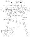
- the left clamping jaw 4 shown in FIGS. 1 and 2 is in a known manner over two by hand crank 5 actuatable spindle drives along the spars 2 slidable.
- the two spars 2 are on their hand cranks 5 opposite ends by a cross member 6 with each other connected. Furthermore, the two spars 2 U-profile open at the bottom, with the U-web forms a floor slide 70.
- the two spars 2 are divided in their longitudinal extent into a fixed spar section 7 and one, in a basic position according to FIGS. 1 and 2, a Extension of this fixed spar section 7 forming and pivotable on this fixed spar section 8.
- the latter carries the spindle-driven Clamping jaw 4.
- the two spar sections 7 and 8 are trained about the same length.
- each fixed spar section 7 In order to form a fixed upper frame, are each on the outside of each fixed spar section 7 extending over the entire length of the spars 2 Cheek plates 9 attached. The latter close on the top flush with the surface of each U-bridge the fixed Spar sections 7 and offer in their over the fixed spar section 7 projecting area a support for the U-webs of the swiveling Spar sections 8 in their horizontal orientation.
- the articulation of the legs is identical design on both sides of the table.
- the leg 11 is at its upper end around a pivot pin 12 pivoted, which in the respective cheek plate 9 is supported.
- the leg 10 is on the other hand lower hinge point around a hinge pin 13 pivoted.
- the legs 10, 11 each have a U-profile and lie with the open side of their U-profile across from.
- the pivot pins 12, 13 each penetrate both side legs of the legs 10, 11, the Hinge pin 12 from an adapted, round bearing bore 14 is received while the pivot pin 13 is received by an elongated hole 15, the longitudinal axis extends in the longitudinal direction of the supporting leg 10.
- the supporting leg 10 has an extension 16 the upper end of which has a snap-in threshold 17 provided recessed recess 18 is formed. With the cover fully open 1 and 2 is a locking pin 19 snapped into the recess 18, which also rigidly supported in the respective cheek plate 9 is.
- the two pillars 10, 11 are via a coupling rod 20 connected, the four between a joint quadrilateral to the articulation points represent, which, however, because of the elongated hole 15th has an additional degree of movement / freedom.
- the pivotable spar section 8 is in its free, the jaw 4 carrying end portion in cross section U-shaped, with a longitudinal extension in the U-web of the spar section 8 extending longitudinal slot 22.
- a drive member 23 passes through this which in the area of the spar section 8, d. H. within of the U-profile, has a threaded bore for Passage of an actuatable by means of the hand crank 5
- Spindle 24 is on the top of the spar section 8 the jaw 4 attached to this drive member 23.
- the two U-legs 25 of the pivotable spar section 8 are extended to form frame cheeks, which is on the inside along the fixed one Spar section 7 and outside along the Cheek plates 9 extend. Are at their free ends this U-leg 25 from one in the fixed Stalk section 7 through pivot pin 26.
- the end regions of the U-legs 25 are further trained enlarged and have a concentric curve slot 27 oriented towards the articulation point, which in turn is interspersed with one, also stored in the fixed beam section 7 Stop pin 28.
- a clamping knob 29 is arranged on the outside. according to this embodiment is the jaw 4 carrying Spar section 8 can be swiveled up into a 90 ° position and can then be fixed using the clamping knob 29. hereafter can the clamping jaw 4 via the spindle drive against the wide surface 30 of the jaw 3 are (see Fig. 10).
- the fixed spar section carrying the jaw 3 7 has one in the area of its U-web Longitudinal slot 31 through which the clamping jaw 3 load-bearing drive member 32 occurs.
- the latter is within the spar section 7, d. H. in the area of the U-profile, firmly connected to one, in the direction of displacement of the clamping jaw 3 extending tie rod 33.
- This tie rod 33 comes into one end, for example in the middle of the spar 2 or in the end area of the fixed Spar section 7 arranged drive box 34 on.
- the latter is fixed in the U-profile Spar section 7 by means of screws 71 on the U-legs attached.
- a detent drive 35 is accommodated in the drive box 34.
- This essentially consists of a locking piece cooperating with the pull rod 33 36 and one, forming a non-return lock 37 Locking piece 72.
- the toothed Drawbar 33 passes through both the locking piece 36 and also the locking piece 72, the latter by appropriate Web arrangements in the drive box 34 can be tilted is stored and with an L-shaped angled free End emerges from the drive box 34 on the underside to form a driving opening 38.
- the locking piece 36 is over a, the tie rod 33 comprising Compression spring 39 against the direction of displacement the jaw 3 against a box-side support web 40 supported.
- the locking piece 72 is by means of another compression spring 41, which is supported on a spring element 42, in a slightly angled, the pull rod 33 against biased a reverse movement blocking position.
- the end 49 of the actuating lever which projects freely outwards 44 is via a pivot pin 50 with a in the U-profile of the leg 10 extending drive rod 51 connected.
- each drive rod 51 of each locking drive 35 within of the associated main leg 10 extends each drive rod 51 of each locking drive 35 within of the associated main leg 10 from the respective actuating lever 44 starting close to the area of one the two legs 10 connecting crossbar 52.
- the latter is also U-shaped and takes a rotatable one in her subspace, over hers Length of two-part shaft 53. On both ends this wave 53, d. H. end of each shaft section in the area of the legs 10, is one, off the U-space towards the other pillar 11 projecting pivot lever 54 attached. Every swivel lever 54 carries a pivot pin 55 for articulating the free, slightly bent end of the respective drive rod 51st
- each pedal 57 with the respectively assigned pivot lever 54 via a Shaft section is rotatably connected and both Pedals 57 can be operated independently of one another.
- the double pedal 56 is designed essentially gate-shaped, each one Pedal 57 has an L-plan and their L-webs assign to each other. The gate formed by this is provided with the reference number 58.
- the drive elements 32 of the jaw 3 gradually one foot together or individually operable.
- a pedal 57 or both pedals 57 simultaneously by foot control depressed.
- the drive shown can also by a Push rod acting clamping pieces can be formed.
- the double pedal arrangement also allows non-prismatic workpieces are clamped, whereby here by pressing one or the other pedal 57 the jaw 3 along one or the other Holmes 2 more or less towards the instep 4 is shifted.
- the double pedal arrangement also an even, parallel shift the jaw 3 feasible, this by a joint operation of the pedals 57.
- the jaw 3 for clamping a small one Workbench only one-sided, d. H. along only of a spar 2 advanced by means of a pedal 57, so a clamping force on the workpiece by the Backstop 37 of the jaw 3 in the area of other Holmes 2 supported.
- the jaw 3 can therefore do not retreat in the area of the other spar 2.
- the rotational return of the actuating lever 44 for Release of the backstop 37 is by a stop 63 in the area of the opening 45 of the drive box 34 limited.
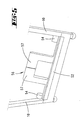
- FIG. 9 shows an alternative embodiment of the drive box 34 shown. Here are for orientation the elements to be used - stop piece 36, Locking piece 72 and spring element 42- instead of molded Crosspieces transverse pins 64 are provided.
- the inventive design is in the simplest Way a freehand actuation when clamping Workpieces guaranteed, with further clamping prismatic workpieces is allowed.
- simultaneous Actuation of the double pedal 56 becomes the clamping jaw 3 moved evenly along the two spars 2.
- By actuating only one pedal 57 is one-sided Displacement of the jaw 3 along a spar 2 feasible.
Landscapes
- Engineering & Computer Science (AREA)
- Mechanical Engineering (AREA)
- Accommodation For Nursing Or Treatment Tables (AREA)
- Jigs For Machine Tools (AREA)
- Forklifts And Lifting Vehicles (AREA)
- Clamps And Clips (AREA)
Claims (15)
- Table de travail (1) comprenant des mors de serrage (3,4) reposant sur deux longerons parallèles (2), au moins l'un (3) de ces mors étant susceptible d'être déplacé en direction de l'autre mors (4) au moyen d'organes d'entraínement (32) associés à chaque longeron et susceptibles d'être actionnés individuellement, caractérisé en ce que les organes d'actionnement (32) comportent chacun un entraínement susceptible d'être actionné pas à pas et sont susceptibles d'être actionnés ensemble ou individuellement au moyen d'un agencement de pédale double actionnée par un seul pied.
- Table de travail (1) selon la revendication 1, caractérisée en ce que l'entraínement comprend une barre (33) de traction ou de poussée fixée au mors de serrage (3), laquelle barre est déplacée pas à pas au moyen de pièces (36) de verrouillage ou de serrage susceptibles d'être déplacées par l'action d'une pédale.
- Table de travail (1) selon l'une des revendications précédentes, caractérisée en ce que l'entraínement (35) de pincement ou de verrouillage comporte un blocage anti-recul (37) susceptible d'être libéré.
- Table de travail (1) selon la revendication 3, caractérisée en ce que le blocage anti-retour (37) est susceptible d'être libéré par un actionnement de retour de pédale.
- Table de travail selon l'une des revendications 2 à 4, caractérisée en ce que la pièce de verrouillage ou de pincement (36) est susceptible d'être déplacée par un levier d'actionnement (44).
- Table de travail selon la revendication 5, caractérisée en ce que le levier d'actionnement (44) est couplé à la pédale (57) par une barre d'actionnement (51).
- Table de travail selon l'une des revendications 5 ou 6, caractérisée en ce que le levier d'actionnement (44) pour libérer le verrouillage antirecul (37), plonge dans une ouverture d'actionnement (38) d'une pièce de blocage (72).
- Table de travail selon l'une des revendications précédentes, caractérisée en ce que la pédale double (56) est disposée sensiblement au milieu d'une traverse (52).
- Table de travail selon l'une des revendications précédentes, caractérisée en ce que la pédale double (56) présente la configuration d'un tore ou d'un portail.
- Table de travail selon l'une des revendications 6 à 9, caractérisée en ce que chaque barre d'actionnement (51) est articulée sur un levier pivotant (54) disposé dans la zone d'une jambe de montant (10) et montée sur un arbre (53) susceptible d'être entraíné en rotation par une pédale à pied (57), et s'étend dans l'espace en forme de U de la jambe de montant (10) présentant un profil en U.
- Table de travail selon l'une des revendications précédentes, caractérisée en ce que l'entraínement de pincement ou de verrouillage (35) est disposé sensiblement au milieu du longeron, en-dessous d'un support de glissement (70) de bâti formé d'un profil de longeron en forme de U.
- Table de travail selon l'une des revendications précédentes, caractérisée en ce que l'autre mors de serrage (4) est monté sur le longeron (2) en étant susceptible d'être déplacé par une broche.
- Table de travail selon l'une des caractérisations précédentes, caractérisée en ce qu'un tronçon (8) de longeron portant l'autre mors de serrage (4) est susceptible d'être pivoté vers le haut dans une position à 90°.
- Table de travail selon la revendication (13), caractérisée en ce que l'autre mors de serrage (4) est susceptible d'être placé, en position pivotée vers le haut, contre la surface élargie (30) du mors de serrage (3) susceptible d'être actionné au pied.
- Table de travail selon l'une des revendications précédentes, caractérisée en ce que les jambes de montant (10, 11) de la table de travail (1) sont repliables et sont arrêtés en position d'utilisation par les longerons (2).
Applications Claiming Priority (3)
| Application Number | Priority Date | Filing Date | Title |
|---|---|---|---|
| DE19735336 | 1997-08-14 | ||
| DE19735336A DE19735336A1 (de) | 1997-08-14 | 1997-08-14 | Werktisch |
| PCT/EP1998/004874 WO1999008840A1 (fr) | 1997-08-14 | 1998-08-05 | Etabli |
Publications (2)
| Publication Number | Publication Date |
|---|---|
| EP1003629A1 EP1003629A1 (fr) | 2000-05-31 |
| EP1003629B1 true EP1003629B1 (fr) | 2003-04-02 |
Family
ID=7839024
Family Applications (1)
| Application Number | Title | Priority Date | Filing Date |
|---|---|---|---|
| EP98943845A Expired - Lifetime EP1003629B1 (fr) | 1997-08-14 | 1998-08-05 | Etabli |
Country Status (5)
| Country | Link |
|---|---|
| US (1) | US6299152B1 (fr) |
| EP (1) | EP1003629B1 (fr) |
| AU (1) | AU9159198A (fr) |
| DE (2) | DE19735336A1 (fr) |
| WO (1) | WO1999008840A1 (fr) |
Families Citing this family (16)
| Publication number | Priority date | Publication date | Assignee | Title |
|---|---|---|---|---|
| US6196534B1 (en) * | 1996-08-07 | 2001-03-06 | Black & Decker Inc. | Work bench including a vise |
| WO2001036164A1 (fr) * | 1999-11-19 | 2001-05-25 | Frank Michael John Kent | Systeme multifonctions de table de travail |
| DE10037805B4 (de) * | 2000-08-03 | 2017-04-06 | Wolfcraft Gmbh | Traggestell, insbesondere Rollenbock |
| US7316250B1 (en) * | 2000-11-18 | 2008-01-08 | Frank Michael John Kent | Multi-functional worktable system |
| GB2393924A (en) * | 2002-09-25 | 2004-04-14 | Huang Mo Hsieh | Turning device for a workbench |
| US7232120B2 (en) * | 2005-07-19 | 2007-06-19 | Black & Decker Inc. | Quick clamping system for a workbench |
| US7784774B2 (en) * | 2006-04-19 | 2010-08-31 | Irwin Industrial Tool Company | Assembly method and apparatus |
| DE102006024291B4 (de) * | 2006-05-24 | 2017-05-04 | Wolfcraft Gmbh | Spannvorrichtung mit schnellverstellbarer Spannbacke |
| USD577507S1 (en) * | 2007-05-03 | 2008-09-30 | Freeform Design & Innovation Limited | Workbench |
| EP2060366A1 (fr) * | 2007-11-13 | 2009-05-20 | Positec Power Tools (Suzhou) Co., Ltd. | Dispositif de serrage |
| CN103009360B (zh) * | 2011-09-21 | 2015-03-11 | 力山工业股份有限公司 | 收折式脚架 |
| CN103009281B (zh) * | 2011-09-22 | 2015-07-01 | 苏州宝时得电动工具有限公司 | 夹具 |
| EP2767369B1 (fr) | 2013-02-15 | 2016-04-20 | The Stanley Works Israel Ltd. | Cadre de banc de travail |
| EP2767368B1 (fr) | 2013-02-15 | 2016-02-10 | The Stanley Works Israel Ltd. | Établi comportant un étau |
| DE102014106961A1 (de) | 2014-05-16 | 2015-11-19 | Wolfcraft Gmbh | Tragegestell mit klapperfrei verriegelbaren Tragelementen |
| GB2549612B (en) * | 2016-04-12 | 2021-12-01 | Power Box Ag | Improvements to clamping apparatus |
Citations (1)
| Publication number | Priority date | Publication date | Assignee | Title |
|---|---|---|---|---|
| DE4418688A1 (de) * | 1994-05-28 | 1995-11-30 | Wolfcraft Gmbh | Spanntisch |
Family Cites Families (16)
| Publication number | Priority date | Publication date | Assignee | Title |
|---|---|---|---|---|
| US738055A (en) * | 1902-08-06 | 1903-09-01 | Edward B Newnam | Foot-vise. |
| GB156719A (en) * | 1919-05-16 | 1921-06-09 | Hans Stirnemann | A new or improved foot-operated vice |
| GB195618A (en) * | 1922-04-03 | 1924-04-03 | Georgie Darwin Bobo | Improvements in vices |
| US1673381A (en) * | 1925-11-12 | 1928-06-12 | Us Slicing Machine Co | Clamp for slicing machines |
| CH156719A (de) | 1931-07-23 | 1932-08-31 | Singer Mfg Co | Mit einer Skala versehene Vorrichtung an Nähmaschinen zum Einstellen der Oberfaden-Spannung. |
| US2424313A (en) * | 1943-05-15 | 1947-07-22 | Robert O Heinrich | Quick locking vise |
| US2892369A (en) * | 1955-12-01 | 1959-06-30 | Millet Ira | Footpower vise |
| DE7513517U (de) * | 1975-04-26 | 1975-08-21 | Keiper Gmbh & Co | Spannvorrichtung |
| US4154435A (en) | 1978-02-22 | 1979-05-15 | The Black And Decker Manufacturing Company | Portable workbench |
| US4184667A (en) * | 1978-02-22 | 1980-01-22 | Black & Decker Inc. | Workpiece supporting and clamping arrangement |
| DE3917473C2 (de) | 1988-08-09 | 1994-10-13 | Petersen Mfg | Schnellspann-Zwinge |
| WO1991008865A1 (fr) * | 1989-12-19 | 1991-06-27 | John Arthur Holman | Mecanisme de blocage pour piece a scier |
| WO1992014581A1 (fr) * | 1991-02-25 | 1992-09-03 | Triton Technologies Pty Ltd | Dispositif de serrage |
| DE4120746A1 (de) | 1991-06-24 | 1993-01-14 | Guenter Heilig | Automatische werkzeugvermessung |
| EP0603344A4 (fr) * | 1991-09-10 | 1995-01-18 | Loxalla Pty Ltd | Dispositifs de serrage. |
| DE4418687C2 (de) | 1994-05-28 | 1996-07-11 | Wolfcraft Gmbh | Zusammenklappbarer Arbeitstisch, insbesondere Spanntisch |
-
1997
- 1997-08-14 DE DE19735336A patent/DE19735336A1/de not_active Ceased
-
1998
- 1998-08-05 WO PCT/EP1998/004874 patent/WO1999008840A1/fr not_active Ceased
- 1998-08-05 EP EP98943845A patent/EP1003629B1/fr not_active Expired - Lifetime
- 1998-08-05 AU AU91591/98A patent/AU9159198A/en not_active Abandoned
- 1998-08-05 DE DE59807754T patent/DE59807754D1/de not_active Expired - Lifetime
- 1998-08-05 US US09/485,480 patent/US6299152B1/en not_active Expired - Fee Related
Patent Citations (1)
| Publication number | Priority date | Publication date | Assignee | Title |
|---|---|---|---|---|
| DE4418688A1 (de) * | 1994-05-28 | 1995-11-30 | Wolfcraft Gmbh | Spanntisch |
Also Published As
| Publication number | Publication date |
|---|---|
| WO1999008840A1 (fr) | 1999-02-25 |
| AU9159198A (en) | 1999-03-08 |
| EP1003629A1 (fr) | 2000-05-31 |
| DE59807754D1 (de) | 2003-05-08 |
| DE19735336A1 (de) | 1999-02-18 |
| US6299152B1 (en) | 2001-10-09 |
Similar Documents
| Publication | Publication Date | Title |
|---|---|---|
| DE19731579A1 (de) | Spannwerkzeug, insbesondere Spannzwinge, Spannstock oder Spanntisch | |
| DE112013007025B4 (de) | Verriegelungsvorrichtung für teleskopierbare Möbelsäule, Möbel und Verfahren | |
| DE8915949U1 (de) | Schnellspann-Zwinge | |
| DE60309798T2 (de) | Klemmvorrichtung für eine Werkbank mit Kunststoffklemmfläche | |
| DE19735336A1 (de) | Werktisch | |
| DE3705330A1 (de) | Tisch | |
| DE3038565C2 (de) | Heftapparat | |
| WO2000073026A2 (fr) | Etrier de serrage a excentrique | |
| EP1138306B1 (fr) | Fauteuil de soins médicaux ou dentaires et repose tête pour un tel fauteuil | |
| DE3141248C2 (de) | Einrichtung zum Zuführen von Schrauben für einen motorbetriebenen Schraubenzieher | |
| DE29614093U1 (de) | Spanntisch | |
| DE102004013066A1 (de) | Spann- und Spreizvorrichtung | |
| EP0997367A2 (fr) | Chassis de poussette pour enfants ou poupées | |
| DE102004047337A1 (de) | Bohrständer | |
| EP2006184A2 (fr) | Mécanisme de poignée de réglage pour chariot roulant, chariot élévateur ou analogue | |
| DE112014006266B4 (de) | Gartenscheren mit Schnitt-Umschaltmodus | |
| DE10328309B4 (de) | Klappgelenk mit Innenverriegelung | |
| DE69602227T2 (de) | Schrittweise arbeitender Vorschubmechanismus für Zangen zum Setzen von Spreizdübeln ode ähnliche Anwendungen | |
| EP0611634B1 (fr) | Couteau à usages multiples | |
| DE69901836T2 (de) | Werkzeug mit selbstverriegelndem griff, auswechselbaren kopfstücken und spannvorrichtung zum befestigen an einem arbeitstisch | |
| DE20213141U1 (de) | Kombinierte Jalousienbeschneidemaschine | |
| DE102006024291B4 (de) | Spannvorrichtung mit schnellverstellbarer Spannbacke | |
| DE102010036834B4 (de) | Werkzeug mit Arbeitsköpfen und Positionierungseinheit | |
| EP1336446A1 (fr) | Butée de profondeur réglable pour outil à main motorisé | |
| DE102015112545B4 (de) | Einspannvorrichtung zum Verspannen eines Werkstücks |
Legal Events
| Date | Code | Title | Description |
|---|---|---|---|
| PUAI | Public reference made under article 153(3) epc to a published international application that has entered the european phase |
Free format text: ORIGINAL CODE: 0009012 |
|
| 17P | Request for examination filed |
Effective date: 20000121 |
|
| AK | Designated contracting states |
Kind code of ref document: A1 Designated state(s): DE FR GB |
|
| GRAH | Despatch of communication of intention to grant a patent |
Free format text: ORIGINAL CODE: EPIDOS IGRA |
|
| GRAH | Despatch of communication of intention to grant a patent |
Free format text: ORIGINAL CODE: EPIDOS IGRA |
|
| GRAA | (expected) grant |
Free format text: ORIGINAL CODE: 0009210 |
|
| AK | Designated contracting states |
Designated state(s): DE FR GB |
|
| REG | Reference to a national code |
Ref country code: GB Ref legal event code: FG4D Free format text: NOT ENGLISH |
|
| REF | Corresponds to: |
Ref document number: 59807754 Country of ref document: DE Date of ref document: 20030508 Kind code of ref document: P |
|
| GBT | Gb: translation of ep patent filed (gb section 77(6)(a)/1977) |
Effective date: 20030514 |
|
| ET | Fr: translation filed | ||
| PLBE | No opposition filed within time limit |
Free format text: ORIGINAL CODE: 0009261 |
|
| STAA | Information on the status of an ep patent application or granted ep patent |
Free format text: STATUS: NO OPPOSITION FILED WITHIN TIME LIMIT |
|
| 26N | No opposition filed |
Effective date: 20040105 |
|
| PGFP | Annual fee paid to national office [announced via postgrant information from national office to epo] |
Ref country code: GB Payment date: 20090812 Year of fee payment: 12 |
|
| GBPC | Gb: european patent ceased through non-payment of renewal fee |
Effective date: 20100805 |
|
| PG25 | Lapsed in a contracting state [announced via postgrant information from national office to epo] |
Ref country code: GB Free format text: LAPSE BECAUSE OF NON-PAYMENT OF DUE FEES Effective date: 20100805 |
|
| PGFP | Annual fee paid to national office [announced via postgrant information from national office to epo] |
Ref country code: DE Payment date: 20140811 Year of fee payment: 17 |
|
| REG | Reference to a national code |
Ref country code: FR Ref legal event code: PLFP Year of fee payment: 18 |
|
| PGFP | Annual fee paid to national office [announced via postgrant information from national office to epo] |
Ref country code: FR Payment date: 20150810 Year of fee payment: 18 |
|
| REG | Reference to a national code |
Ref country code: DE Ref legal event code: R119 Ref document number: 59807754 Country of ref document: DE |
|
| PG25 | Lapsed in a contracting state [announced via postgrant information from national office to epo] |
Ref country code: DE Free format text: LAPSE BECAUSE OF NON-PAYMENT OF DUE FEES Effective date: 20160301 |
|
| REG | Reference to a national code |
Ref country code: FR Ref legal event code: ST Effective date: 20170428 |
|
| PG25 | Lapsed in a contracting state [announced via postgrant information from national office to epo] |
Ref country code: FR Free format text: LAPSE BECAUSE OF NON-PAYMENT OF DUE FEES Effective date: 20160831 |