EP1003642B1 - Installation pour la production d'articles imprimes en forme de feuilles - Google Patents
Installation pour la production d'articles imprimes en forme de feuilles Download PDFInfo
- Publication number
- EP1003642B1 EP1003642B1 EP98946300A EP98946300A EP1003642B1 EP 1003642 B1 EP1003642 B1 EP 1003642B1 EP 98946300 A EP98946300 A EP 98946300A EP 98946300 A EP98946300 A EP 98946300A EP 1003642 B1 EP1003642 B1 EP 1003642B1
- Authority
- EP
- European Patent Office
- Prior art keywords
- printing
- installation according
- station
- output items
- printed
- Prior art date
- Legal status (The legal status is an assumption and is not a legal conclusion. Google has not performed a legal analysis and makes no representation as to the accuracy of the status listed.)
- Expired - Lifetime
Links
- 238000009434 installation Methods 0.000 title claims 18
- 238000001035 drying Methods 0.000 claims description 16
- 238000012546 transfer Methods 0.000 claims description 11
- 239000000463 material Substances 0.000 claims description 7
- 230000005855 radiation Effects 0.000 claims description 5
- 238000011282 treatment Methods 0.000 claims description 5
- 238000013461 design Methods 0.000 claims description 3
- 238000000926 separation method Methods 0.000 claims description 2
- 238000004519 manufacturing process Methods 0.000 claims 1
- 238000012545 processing Methods 0.000 description 6
- 238000000034 method Methods 0.000 description 5
- 239000007858 starting material Substances 0.000 description 5
- 230000000694 effects Effects 0.000 description 2
- 238000005516 engineering process Methods 0.000 description 2
- 239000003973 paint Substances 0.000 description 2
- 239000002994 raw material Substances 0.000 description 2
- 230000009286 beneficial effect Effects 0.000 description 1
- 239000011111 cardboard Substances 0.000 description 1
- 238000002508 contact lithography Methods 0.000 description 1
- 238000011161 development Methods 0.000 description 1
- 230000018109 developmental process Effects 0.000 description 1
- 239000011888 foil Substances 0.000 description 1
- 239000002184 metal Substances 0.000 description 1
- 239000000123 paper Substances 0.000 description 1
- 239000011087 paperboard Substances 0.000 description 1
- 239000002245 particle Substances 0.000 description 1
- 230000000149 penetrating effect Effects 0.000 description 1
- 230000004044 response Effects 0.000 description 1
- 238000009420 retrofitting Methods 0.000 description 1
- 238000011144 upstream manufacturing Methods 0.000 description 1
Images
Classifications
-
- B—PERFORMING OPERATIONS; TRANSPORTING
- B41—PRINTING; LINING MACHINES; TYPEWRITERS; STAMPS
- B41J—TYPEWRITERS; SELECTIVE PRINTING MECHANISMS, i.e. MECHANISMS PRINTING OTHERWISE THAN FROM A FORME; CORRECTION OF TYPOGRAPHICAL ERRORS
- B41J11/00—Devices or arrangements of selective printing mechanisms, e.g. ink-jet printers or thermal printers, for supporting or handling copy material in sheet or web form
- B41J11/0085—Using suction for maintaining printing material flat
-
- B—PERFORMING OPERATIONS; TRANSPORTING
- B41—PRINTING; LINING MACHINES; TYPEWRITERS; STAMPS
- B41J—TYPEWRITERS; SELECTIVE PRINTING MECHANISMS, i.e. MECHANISMS PRINTING OTHERWISE THAN FROM A FORME; CORRECTION OF TYPOGRAPHICAL ERRORS
- B41J11/00—Devices or arrangements of selective printing mechanisms, e.g. ink-jet printers or thermal printers, for supporting or handling copy material in sheet or web form
- B41J11/0015—Devices or arrangements of selective printing mechanisms, e.g. ink-jet printers or thermal printers, for supporting or handling copy material in sheet or web form for treating before, during or after printing or for uniform coating or laminating the copy material before or after printing
- B41J11/002—Curing or drying the ink on the copy materials, e.g. by heating or irradiating
- B41J11/0021—Curing or drying the ink on the copy materials, e.g. by heating or irradiating using irradiation
- B41J11/00216—Curing or drying the ink on the copy materials, e.g. by heating or irradiating using irradiation using infrared [IR] radiation or microwaves
-
- B—PERFORMING OPERATIONS; TRANSPORTING
- B41—PRINTING; LINING MACHINES; TYPEWRITERS; STAMPS
- B41J—TYPEWRITERS; SELECTIVE PRINTING MECHANISMS, i.e. MECHANISMS PRINTING OTHERWISE THAN FROM A FORME; CORRECTION OF TYPOGRAPHICAL ERRORS
- B41J11/00—Devices or arrangements of selective printing mechanisms, e.g. ink-jet printers or thermal printers, for supporting or handling copy material in sheet or web form
- B41J11/007—Conveyor belts or like feeding devices
-
- B—PERFORMING OPERATIONS; TRANSPORTING
- B41—PRINTING; LINING MACHINES; TYPEWRITERS; STAMPS
- B41J—TYPEWRITERS; SELECTIVE PRINTING MECHANISMS, i.e. MECHANISMS PRINTING OTHERWISE THAN FROM A FORME; CORRECTION OF TYPOGRAPHICAL ERRORS
- B41J3/00—Typewriters or selective printing or marking mechanisms characterised by the purpose for which they are constructed
- B41J3/60—Typewriters or selective printing or marking mechanisms characterised by the purpose for which they are constructed for printing on both faces of the printing material
Definitions
- the invention relates to a plant for creating sheet-like Printed matter, e.g. brochures, magazines or invoice sheets, with a transport device to the starting material to be printed and fed to a feed station transported through a printing station in which at least one printed image is applied to the starting material becomes.
- a transport device to the starting material to be printed and fed to a feed station transported through a printing station in which at least one printed image is applied to the starting material becomes.
- the downstream Drying device guaranteed even at high Working speed reliable drying of the passing printed output parts, so that the printed image is fixed and can no longer blur. That of the print image application device assigned electronic print image specification device makes it possible to operate the Plant to intervene in the printing process and the individual Assign individual print images to output parts as required, so that not only printed matter with the same Printed image, but also with printed products individualized print image can be created. So can for example personal invoice sheets or Cover letters are created with recipient-specific Content to be printed.
- DE-OS 23 43 109 discloses a feed device for leaf-shaped objects with a vacuum conveyor belt Is provided.
- a printer is known from EP 0 284 215 A1 out, the with an infrared-based drying device Is provided.
- DE 195 27264 A1 describes a printing press which has several printing stations, between which turning devices for those to be printed Objects are arranged.
- DE 44 25 199 A1 discloses a printing device for printing web-like Material, with several printheads that are provided by a control unit can be controlled to variably different Generate print images.
- Another advantage of the system is that it works with continuous transport of the starting parts to be printed can be operated so that none reduces the throughput Downtimes occur.
- a transport speed is realistic of quite 300 m / min., what with sheet formats usual size the printing of about 54000 pieces per hour allowed.
- the system expediently has a delivery station, in which the printed and dried starting parts, now that is, the print products created are taken over to to be able to send them for further treatment if necessary.
- the supply of further treatments can be continuous done, but it is also possible to stack the printed products until further transport.
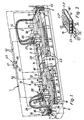
- FIG. 1 shows a system 1 which enables also starting from leaf-shaped starting parts 2 to create sheet-like printed products 3.
- the output parts 2 pass through the plant 1 one after the other, always at the same time several output parts 2 in the course of the system 1 are, the output parts 2 on one or, as in the Embodiment, on both of their opposite flat pages can be provided with a printed image.
- sheets of brochures or magazines or even Invoice sheets or others with individual imprints provided formatted and incoherent printed matter 3 can be produced.
- Appendix 1 of the exemplary embodiment has a Transport device 4, which is largely from a vacuum conveyor belt device 5 is formed.
- This transport facility 4 runs between a feed station 6 and a delivery station 7, with a linear as shown horizontal course can be provided.
- the output parts 2 to be printed pass through system 1 during processing in a direction indicated by arrows Transport direction 12 starting from the feed station 6 to Dispensing station 7.
- the exit parts 2 pass through one after the other a first printing station 13, a turning station 14 and a second printing station 15.
- the vacuum conveyor 5 includes in the embodiment two belt units 8, 8 ', one of which (8) between the feed station 6 and the turning station 14 runs while the other (8 ') between the turning station 14 and the delivery station 7 is arranged.
- the first tape unit 8 passes through the first printing station 13, the second Belt unit 8 'passes through the second printing station 15.
- each Conveyor belt 17 is designed as an endless belt that around at least two horizontally spaced Deflection rollers 18, 18 'is wrapped around, the Rotation axes parallel to each other horizontally and at right angles run to the transport direction 12.
- At least one the deflection rollers 18, 18 'of a respective belt unit 8, 8' stands with a drive motor not shown in Connection that creates the rotary drive to the conveyor belts 17 on their unidirectional orbital movement around the Drive pulleys 18, 18 '.
- the conveyor belt 17 is advantageously a metal belt executed and has a distributed over the band level A plurality of the conveyor belt 17 at right angles to the plane of expansion penetrating suction openings 22 (cf. Fig. 2). Between the upper band strand 16 and the lower Belt strand 16 'of each conveyor belt 17 extends e.g. box-like vacuum chamber assembly 23, the one or more in the longitudinal direction of the respective belt unit 8, 8 'extending vacuum chambers 24 which connect to one Vacuum generator V, for example a suction pump, connected are. This causes one in the vacuum chambers 24 Suction effect, which leads to the suction openings 22 of the upper band strand 16 air from the Environment is sucked in, which leads to that on the upper band strand 16 stored flat output part 2 is sucked in and held.
- V Vacuum generator
- the vacuum chambers 24 are variable can be switched on or off by between each vacuum chamber 24 and the vacuum generator V a shut-off valve 25 is interposed, with which the connection can either produce or interrupt. In this way can be depending on the format of the transported Output parts 2 any of the vacuum chambers 24 activated and be deactivated.
- FIG. 2 In the embodiment of FIG. 2, four are side by side, elongated vacuum chambers 24 available, the 2 'larger for holding output parts Format all activated and with the vacuum generator V are connected. Can hold 2 "of output parts the two outer vacuum chambers 24 by closing the Shutoff valves 25 are deactivated, so that also with the suction openings 22 communicating with these vacuum chambers no suction effect occurs and an output part 2 '' smaller Formats is held only by the negative pressure that via the communicating with the two inner vacuum chambers 24 Suction openings 22 acts.
- the materials of the sheet-like starting parts to be printed In principle, 2 are arbitrary, but usually it will usually thin paper or cardboard materials similar to foils act.
- the Output parts 2 aligned, for example, in a horizontal plane.
- the output parts 2 are rotated by 180 °, so that the previously the second side facing downward is directed upwards and now in turn as it passes through the second printing station 15 is printed.
- the handling of the output parts 2 in the turning station 14 can also done on a vacuum basis.
- the structure of the two printing stations 13, 15 is in the embodiment identical, so that the present Description to that following the feed station 6 first printing station 13 limited. The related statements apply accordingly to the second printing station 15.
- the printing station 13 has a preferably contactless working image application device 26, the in the embodiment as an ink jet application device is executed. In the present case, it comprises several side by side arranged application units 27, the connecting hoses 28 and intermediate, not shown Pumps are connected to ink reservoir 29. The order units 27 are fed from these, the Most of the order units 27 except for single color printing Multi-color printing is also readily permitted.
- the application units 27 are a short distance above arranged the imaginary transport path along which the output parts 2 to be printed during the passage of the Move attachment 1.
- Color jets emitted under pressure or Ink jets produce the desired print image in the shortest possible time - This can be, for example, any text, images or Graphics - on the output part 2 to be printed, the is currently working on the print image application device 26 passed at high speed.
- a reliable fixation of the to receive the applied print image is the print image application device 26 in the transport direction 12 a drying device 32 connected by the output parts 2 after printing.
- the infrared radiation works highly effectively and causes the paint particles to dry quickly.
- the drying device 32 is like pictured along at least one piece the transport path of the output parts 2 extending surface dryer 33, the one with horizontal alignment above of the conveyor belt 17 with the smallest possible distance to Transport track can be arranged. It can be as shown have an essentially hood-like shape.
- the feed station 6 already mentioned is in the embodiment designed to process in Stacked form existing output parts 2 allows.
- a stack of starting parts is indicated at 34.
- the transfer of the output parts 2 from the feed station 6 to the subsequent belt unit 8 is done with the help a transfer device 35, which in the embodiment with a separating device 36 is equipped.
- Latter may have a vacuum suction assembly 37, each the uppermost output part 2 lifts off the output parts stack 34 and according to arrow 38 onto the upper band strand 16 of the band unit 8 stores.
- the transfer device is also considered advantageous 35 so that they form the output parts to be transferred 2nd pre-accelerated on the running conveyor belt 17 of the neighboring one Tape unit 8 passes.
- it is considered appropriate deemed the starting parts at a transfer speed to pass on the conveyor belt 17, at least essentially with the tape speed and the amount is the same.
- the Transfer device 42 can be designed so that the Printed products 3 continuously downstream to another Finishing treatment to be forwarded. At the The printed products created by the transfer device 42 stacked and can then as Stack are transported away.
- the described system enables the highest precision Processing speeds.
- there is a high degree of processing flexibility given by a quick response to unexpectedly received print jobs is possible as well as in particular also individual sheet-related printing by that is, immediately immediately following leaf-shaped ones Starting parts with different print images can be provided.
- the flexibility is achieved by at least with the Print image application device 26 of all existing printing stations 13, 15 cooperating electronic print image specification device 43, indicated schematically in Fig. 1 is.
- the other facilities of the System 1 control technology with the print image specification device 43 linked.
- a link to the drive devices of the transport device 4, with the two print image applicators 26, with the two drying devices 32, with the feed station 6 and with the delivery station 7, the corresponding Control lines are indicated at 44. In this way overall control is possible in which all Movements are reliably coordinated with each other.
- the print image specification device 43 enables in particular a variable specification by the print image application devices 26 print images to be generated, in such a way that a sheet-related, that is specific to the individual Output parts coordinated specification is possible. This allows a kind of personalization by customizing the printed image based on specifications that are specific to a particular Recipients are aligned.
- the print image specification device 43 may include a memory in which any number of printed images is stored, the queried during operation of the system and accordingly the print image application devices 26 are controlled.
- the print image specification device comprises 43 including a display 45 to show the Operational sequence and also an alpha-numeric input field 46.
- An interface 47 can also be seen, the one Connection to an external computer system, so that a convenient data transfer between a computer and the Print image specification device 43 is possible.
- the coordination between the print order and the Transport of the output parts 2 to be printed takes place expediently using a not shown Sensor technology, the specific positions of the continuously transported output parts 2 can capture, so that the paint application to the output parts 2 always under Inclusion of the transport speed of the starting parts 2 can be done correctly.
- the one position entry of the transported output parts 2 enabling sensors in Connection with the control-technical connection of the Print image specification device 43 and the other relevant Facilities of plant 1 a very flexible mode of operation enabled at high working speed.
- the printing process and the transport speed are linked, so that when printing one for example with regard to changed product specifications change in transport speed Can be taken into account and always consistently high quality print result becomes. Also possible operational fluctuations in the Transport speed can be controlled via the control Linking on the part of the printing process is easily compensated become.
Landscapes
- Health & Medical Sciences (AREA)
- General Health & Medical Sciences (AREA)
- Toxicology (AREA)
- Ink Jet (AREA)
- Supply, Installation And Extraction Of Printed Sheets Or Plates (AREA)
- Discharge By Other Means (AREA)
- Delivering By Means Of Belts And Rollers (AREA)
Claims (16)
- Installation de fabrication d'imprimés (3) du type en feuilles, par exemple de prospectus, de magazines ou de factures, comprenant un dispositif de transport (4) qui achemine, à travers un poste d'impression (13), un matériau de départ à imprimer, amené au niveau d'un poste d'amenée (6), poste d'impression (13) dans lequel au moins une image à imprimer est apposée sur le matériau de base, le poste d'amenée (6) comprenant un dispositif de transfert (35) servant à transférer, sur le dispositif de transport (4), le matériau de départ se présentant sous la forme d'éléments de départ (2) en forme de feuilles, et le poste d'impression (13) disposant d'un dispositif d'application d'image à imprimer (26), fonctionnant sans contact, et comprenant un dispositif électronique d'attribution d'image à imprimer (43), fonctionnant avec le dispositif d'application d'image à imprimer (26), permettant d'attribuer individuellement des images à imprimer, associées à une feuille, caractérisée en ce que le dispositif de transport (4) est équipé d'un dispositif formant bande transporteuse à vide (5) sur lequel les éléments de départ (2) sous forme de feuilles, destinés à être imprimés, sont maintenus, grâce à l'action du vide, pendant leur transport, en ce que le poste d'impression (13) comprend un dispositif de séchage (32) monté en aval du dispositif d'application d'image à imprimer (26), dans la direction de transport (12) des éléments de départ (2), en ce qu'une analyse sensorielle est réalisée pour détecter certaines positions des éléments de base (2) transportés en continu, et en ce que la commande du dispositif d'attribution d'image à imprimer (43) est liée à celle du poste d'amenée (6), du dispositif de transport (4) et du dispositif de séchage (32).
- Installation selon la revendication 1, caractérisée en ce que le dispositif de transfert (35) comprend un dispositif de déliassage (36) qui transfère, sur le dispositif de transport (4), les éléments de départ (2) empilés, sous forme d'éléments de départ (2) séparés.
- Installation selon la revendication 1 ou 2, caractérisée en ce que le dispositif de transfert (35) est conçu de telle sorte qu'il transfère, sur le dispositif formant bande transporteuse à vide, circulant, les éléments de départ (2) séparés, à l'état préaccéléré et, avantageusement, avec une vitesse de transfert correspondant à la vitesse de circulation de la bande et agissant dans la même direction.
- Installation selon l'une des revendications 1 à 3, caractérisée en ce que le dispositif d'application d'image à imprimer (26) est conçu pour une application monochrome et/ou polychrome d'image à imprimer.
- Installation selon l'une des revendications 1 à 4, caractérisée en ce que sont prévus plusieurs réservoirs d'encre d'imprimerie de couleur (29) servant à alimenter le dispositif d'application d'image à imprimer (26).
- Installation selon l'une des revendications 1 à 5, caractérisée en ce que le dispositif de séchage (32) comprend au moins un sécheur superficiel (33) s'étendant sur une partie de la longueur du parcours de transport des éléments de départ (2).
- Installation selon l'une des revendications 1 à 6, caractérisée en ce que le dispositif de séchage (32) fonctionne à l'aide de rayonnements infrarouges et, en particulier, en produisant ce que l'on appelle des rayons infrarouges proches.
- Installation selon l'une des revendications 1 à 7, caractérisée en ce que le parcours de transport des éléments de départ (2) est horizontal lorsqu'ils parcourent le poste d'impression (13), les éléments de départ (2) du type en feuilles étant orientés dans un plan horizontal et le dispositif d'application d'image à imprimer (26) et le dispositif de séchage (32) étant montés sur le parcours de transport.
- Installation selon l'une des revendications 1 à 8, caractérisée en ce que le dispositif formant bande transporteuse à vide (5) est équipé de chambres à vide (24) adjacentes, activables ou désactivables de façon variable, s'étendant dans la direction de transport (12) des éléments de départ (2).
- Installation selon l'une des revendications 1 à 9, caractérisée par un fonctionnement avec transport en continu des éléments de départ (2).
- Installation selon l'une des revendications 1 à 10, caractérisée en ce qu'est prévu un poste de retournement (14), dans lequel les éléments de départ (2), imprimés sur une face dans le poste d'impression, sont retournés de façon à ce que leur face opposée puisse être imprimée.
- Installation selon la revendication 11, caractérisée en ce qu'un poste d'impression (15) supplémentaire fait suite au poste de retournement (14), dans la direction de transport (12) des éléments de départ (2), poste supplémentaire dans lequel l'autre face, déjà évoquée, des éléments de départ (2) du type feuilles retournés peuvent être imprimés.
- Installation selon la revendication 12, caractérisée en ce que la structure et la commande du poste d'impression (15) supplémentaire correspondent entièrement ou partiellement à celles du premier poste d'impression (13) situé en amont.
- Installation selon l'une des revendications 1 à 13, caractérisée par un parcours sensiblement horizontal des éléments de départ (2) au cours des processus d'impression.
- Installation selon l'une des revendications 1 à 14, caractérisée par un poste de dépôt (7) dans lequel les imprimés (3), une fois imprimés, sont pris en charge par le dispositif formant bande transporteuse à vide (5) pour subir un traitement ultérieur, poste qui est également avantageusement commandé en liaison avec le dispositif d'attribution d'image à imprimer (43).
- Installation selon l'une des revendications 1 à 15, caractérisée en ce que le dispositif d'application d'image à imprimer (26) est un dispositif d'application à jet d'encre.
Applications Claiming Priority (3)
| Application Number | Priority Date | Filing Date | Title |
|---|---|---|---|
| DE19735070 | 1997-08-13 | ||
| DE19735070A DE19735070C2 (de) | 1997-08-13 | 1997-08-13 | Anlage zum Erstellen blattartiger Druckerzeugnisse |
| PCT/EP1998/005016 WO1999008878A1 (fr) | 1997-08-13 | 1998-08-07 | Installation pour la production d'articles imprimes en forme de feuilles |
Publications (2)
| Publication Number | Publication Date |
|---|---|
| EP1003642A1 EP1003642A1 (fr) | 2000-05-31 |
| EP1003642B1 true EP1003642B1 (fr) | 2002-01-16 |
Family
ID=7838847
Family Applications (1)
| Application Number | Title | Priority Date | Filing Date |
|---|---|---|---|
| EP98946300A Expired - Lifetime EP1003642B1 (fr) | 1997-08-13 | 1998-08-07 | Installation pour la production d'articles imprimes en forme de feuilles |
Country Status (6)
| Country | Link |
|---|---|
| US (1) | US6471430B1 (fr) |
| EP (1) | EP1003642B1 (fr) |
| AU (1) | AU9340498A (fr) |
| DE (2) | DE19735070C2 (fr) |
| ES (1) | ES2172199T3 (fr) |
| WO (1) | WO1999008878A1 (fr) |
Families Citing this family (17)
| Publication number | Priority date | Publication date | Assignee | Title |
|---|---|---|---|---|
| DE19929323A1 (de) * | 1999-06-25 | 2000-12-28 | Eastman Kodak Co | Tintenstrahldrucker für die Herstellung von Fotoabzügen |
| DE19929322A1 (de) | 1999-06-25 | 2000-12-28 | Eastman Kodak Co | Tintenstrahldrucker für die Herstellung von Fotoabzügen |
| DE10009822C1 (de) * | 2000-03-01 | 2001-12-06 | Basf Coatings Ag | Verfahren zur Herstellung von Beschichtungen, Klebschichten oder Dichtungen für grundierte oder ungrundierte Substrate und Substrate |
| US6477950B1 (en) * | 2000-04-12 | 2002-11-12 | Michael Alan Feilen | Apparatus and method for duplex printing of a sheet-like substrate |
| DE10038897B4 (de) * | 2000-08-09 | 2006-03-02 | Advanced Photonics Technologies Ag | Verfahren und Vorrichtung zum Trocknen von Tintenstrahldrucken |
| JP2004291493A (ja) * | 2003-03-27 | 2004-10-21 | Brother Ind Ltd | 印刷装置、印刷システム及び印刷方法 |
| DE10316472A1 (de) * | 2003-04-09 | 2004-10-28 | Heidelberger Druckmaschinen Ag | Verfahren zum Trocknen einer Druckfarbe auf einem Bedruckstoff in einer Druckmaschine und Druckmaschine |
| US20110016739A1 (en) * | 2009-05-06 | 2011-01-27 | Bescorp. Inc. | Multi-directional conveyor and method |
| US8465578B2 (en) | 2011-03-31 | 2013-06-18 | Eastman Kodak Company | Inkjet printing ink set |
| US8398223B2 (en) * | 2011-03-31 | 2013-03-19 | Eastman Kodak Company | Inkjet printing process |
| US10035166B2 (en) | 2014-07-18 | 2018-07-31 | Bobst Mex Sa | Coating unit for applying a coating substance in a machine for printing flat media |
| EP3169527A1 (fr) | 2014-07-18 | 2017-05-24 | Bobst Mex Sa | Caisson d'aspiration pour système de transport de supports plans et machine d'impression ainsi équipée |
| WO2016008596A1 (fr) | 2014-07-18 | 2016-01-21 | Bobst Mex Sa | Caisson d'aspiration, systeme de transport de supports plans, et machine d'impression ainsi equipee |
| EP3621571B1 (fr) | 2017-05-12 | 2023-06-14 | The Procter & Gamble Company | Article d'hygiène féminine |
| EP3621572B1 (fr) | 2017-05-12 | 2026-04-29 | The Procter & Gamble Company | Article d'hygiène féminine |
| EP4450038A3 (fr) | 2017-05-12 | 2025-01-01 | The Procter & Gamble Company | Article d'hygiène féminine |
| WO2018213225A1 (fr) * | 2017-05-17 | 2018-11-22 | The Procter & Gamble Company | Procédé et appareil de séchage d'encres imprimées sur des composants d'article absorbant thermosensible |
Family Cites Families (12)
| Publication number | Priority date | Publication date | Assignee | Title |
|---|---|---|---|---|
| DD103365A1 (fr) * | 1973-01-18 | 1974-01-12 | ||
| US4774523A (en) * | 1987-03-25 | 1988-09-27 | Hewlett-Packard Company | Method and apparatus for uniformly drying ink on paper from an ink jet printer |
| US5280308A (en) * | 1989-02-23 | 1994-01-18 | Canon Kabushiki Kaisha | Sheet feeding device |
| DE9111877U1 (de) * | 1991-09-23 | 1991-11-14 | Franz Drexel GmbH, 86415 Mering | Anlage zum Bedrucken bzw. Bemustern von flachen Gegenständen aus Karton oder kartonähnlichen Materialien |
| JPH0792831A (ja) * | 1993-08-11 | 1995-04-07 | Kiyotsukou Seiko Kk | ハロゲンランプにおける赤外線照射方法 |
| US5668581A (en) * | 1993-10-27 | 1997-09-16 | Mita Industrial Co., Ltd. | Ink jet printing apparatus |
| DE4425199A1 (de) * | 1994-07-16 | 1996-01-18 | Heinr Aug Schoeller Soehne Gmb | Verfahren zum Bedrucken von Wellpappe sowie Einrichtung zur Durchführung des Verfahrens |
| DE4442629C2 (de) * | 1994-12-01 | 1998-05-07 | Heidelberger Druckmasch Ag | Saugbändertisch |
| US5717446A (en) * | 1994-12-12 | 1998-02-10 | Xerox Corporation | Liquid ink printer including a vacuum transport system and method of purging ink in the printer |
| DE19527264A1 (de) * | 1995-07-26 | 1997-01-30 | Heidelberger Druckmasch Ag | Druckmaschine mit geradliniger Substratführung und Wendeeinrichtungen dafür |
| US5764263A (en) * | 1996-02-05 | 1998-06-09 | Xerox Corporation | Printing process, apparatus, and materials for the reduction of paper curl |
| US5757407A (en) * | 1996-11-25 | 1998-05-26 | Xerox Corporation | Liquid ink printer having multiple pass drying |
-
1997
- 1997-08-13 DE DE19735070A patent/DE19735070C2/de not_active Expired - Lifetime
-
1998
- 1998-08-07 WO PCT/EP1998/005016 patent/WO1999008878A1/fr not_active Ceased
- 1998-08-07 AU AU93404/98A patent/AU9340498A/en not_active Abandoned
- 1998-08-07 EP EP98946300A patent/EP1003642B1/fr not_active Expired - Lifetime
- 1998-08-07 DE DE59802651T patent/DE59802651D1/de not_active Expired - Fee Related
- 1998-08-07 ES ES98946300T patent/ES2172199T3/es not_active Expired - Lifetime
- 1998-08-07 US US09/485,589 patent/US6471430B1/en not_active Expired - Lifetime
Also Published As
| Publication number | Publication date |
|---|---|
| AU9340498A (en) | 1999-03-08 |
| DE19735070A1 (de) | 1999-02-18 |
| EP1003642A1 (fr) | 2000-05-31 |
| DE19735070C2 (de) | 2001-09-06 |
| ES2172199T3 (es) | 2002-09-16 |
| US6471430B1 (en) | 2002-10-29 |
| DE59802651D1 (de) | 2002-02-21 |
| WO1999008878A1 (fr) | 1999-02-25 |
Similar Documents
| Publication | Publication Date | Title |
|---|---|---|
| EP1003642B1 (fr) | Installation pour la production d'articles imprimes en forme de feuilles | |
| EP3253575B1 (fr) | Ensemble machine et procédé de traitement séquentiel de substrats sous forme de feuilles | |
| EP3543015B1 (fr) | Ensemble machine à plusieurs stations avec unité d'impression pour le traitement séquentiel de substrats sous forme de feuilles | |
| DE10312153A1 (de) | Maschine für den Bogenrotationsdruck oder Bogenbeschichtung | |
| DE102015017091A1 (de) | Maschinenanordnung mit mehreren Bearbeitungsstationen zur Bearbeitung von Bogen | |
| DE102015208043A1 (de) | Maschinenanordnung mit mehreren Bearbeitungsstationen zur Bearbeitung von Bogen | |
| DE102015208046B4 (de) | Maschinenanordnung mit mehreren Bearbeitungsstationen zur Bearbeitung von Bogen | |
| EP3072690B1 (fr) | Machine d'impression de feuilles et station d'acceleration | |
| DE102015208042B4 (de) | Maschinenanordnung mit mehreren Bearbeitungsstationen zur Bearbeitung von Bogen | |
| DE29724445U1 (de) | Anlage zum Erstellen blattartiger Druckerzeugnisse | |
| DE102015208050A1 (de) | Verfahren zum Betrieb einer Transporteinrichtung zum Transport von Bogen in einer Anordnung von mehreren jeweils Bogen bearbeitenden Bearbeitungsstationen | |
| DE102015017156B4 (de) | Verfahren zum Betrieb einer Transporteinrichtung zum Transport von Bogen in einer Anordnung von mehreren jeweils Bogen bearbeitenden Bearbeitungsstationen | |
| EP1764329A2 (fr) | Machine d'impression de feuilles | |
| DE102015208047B4 (de) | Verfahren zum Anordnen von Bogen in einer geschuppten Lage | |
| DE102015208045B4 (de) | Maschinenanordnung mit einer Bogendruckmaschine mit mehreren Druckwerken in Reihenbauweise | |
| DE102015208049B4 (de) | Transporteinrichtung zum Transport von Bogen in einer Anordnung von mehreren jeweils Bogen bearbeitenden Bearbeitungsstationen | |
| DE102015208044B4 (de) | Maschinenanordnung mit mehreren Bearbeitungsstationen zur Bearbeitung von Bogen | |
| DE102016214902B4 (de) | Maschinenanordnung zum sequentiellen Bearbeiten bogenförmiger Substrate | |
| DE102016214906B4 (de) | Maschinenanordnung zum sequentiellen Bearbeiten bogenförmiger Substrate | |
| WO2025176391A1 (fr) | Procédé et dispositif d'impression sur les deux côtés de supports d'impression | |
| DE102015213429A1 (de) | Transportvorrichtung zum sequentiellen Transport einzelner bogenförmiger Substrate | |
| DE102016214898A1 (de) | Maschinenanordnung zum sequentiellen Bearbeiten bogenförmiger Substrate | |
| DE102016214901A1 (de) | Maschinenanordnung zum sequentiellen Bearbeiten bogenförmiger Substrate |
Legal Events
| Date | Code | Title | Description |
|---|---|---|---|
| PUAI | Public reference made under article 153(3) epc to a published international application that has entered the european phase |
Free format text: ORIGINAL CODE: 0009012 |
|
| 17P | Request for examination filed |
Effective date: 20000217 |
|
| AK | Designated contracting states |
Kind code of ref document: A1 Designated state(s): DE ES FR GB IT |
|
| RIN1 | Information on inventor provided before grant (corrected) |
Inventor name: BAER, KAI, K.O. Inventor name: BACH, GERHARD Inventor name: GAUS, RAINER |
|
| RAP1 | Party data changed (applicant data changed or rights of an application transferred) |
Owner name: INDUSTRIESERVIS GESELLSCHAFT FUER INNOVATION TECHN |
|
| RAP1 | Party data changed (applicant data changed or rights of an application transferred) |
Owner name: ADVANCED PHOTONICS TECHNOLOGIES AG |
|
| GRAG | Despatch of communication of intention to grant |
Free format text: ORIGINAL CODE: EPIDOS AGRA |
|
| 17Q | First examination report despatched |
Effective date: 20010305 |
|
| GRAG | Despatch of communication of intention to grant |
Free format text: ORIGINAL CODE: EPIDOS AGRA |
|
| GRAH | Despatch of communication of intention to grant a patent |
Free format text: ORIGINAL CODE: EPIDOS IGRA |
|
| GRAH | Despatch of communication of intention to grant a patent |
Free format text: ORIGINAL CODE: EPIDOS IGRA |
|
| GRAA | (expected) grant |
Free format text: ORIGINAL CODE: 0009210 |
|
| REG | Reference to a national code |
Ref country code: GB Ref legal event code: IF02 |
|
| AK | Designated contracting states |
Kind code of ref document: B1 Designated state(s): DE ES FR GB IT |
|
| REF | Corresponds to: |
Ref document number: 59802651 Country of ref document: DE Date of ref document: 20020221 |
|
| GBT | Gb: translation of ep patent filed (gb section 77(6)(a)/1977) |
Effective date: 20020415 |
|
| ET | Fr: translation filed | ||
| REG | Reference to a national code |
Ref country code: ES Ref legal event code: FG2A Ref document number: 2172199 Country of ref document: ES Kind code of ref document: T3 |
|
| PGFP | Annual fee paid to national office [announced via postgrant information from national office to epo] |
Ref country code: DE Payment date: 20021030 Year of fee payment: 5 |
|
| PLBE | No opposition filed within time limit |
Free format text: ORIGINAL CODE: 0009261 |
|
| STAA | Information on the status of an ep patent application or granted ep patent |
Free format text: STATUS: NO OPPOSITION FILED WITHIN TIME LIMIT |
|
| 26N | No opposition filed | ||
| PG25 | Lapsed in a contracting state [announced via postgrant information from national office to epo] |
Ref country code: DE Free format text: LAPSE BECAUSE OF NON-PAYMENT OF DUE FEES Effective date: 20040302 |
|
| PG25 | Lapsed in a contracting state [announced via postgrant information from national office to epo] |
Ref country code: IT Free format text: LAPSE BECAUSE OF NON-PAYMENT OF DUE FEES Effective date: 20100807 |
|
| PGFP | Annual fee paid to national office [announced via postgrant information from national office to epo] |
Ref country code: ES Payment date: 20140827 Year of fee payment: 17 |
|
| REG | Reference to a national code |
Ref country code: ES Ref legal event code: FD2A Effective date: 20160926 |
|
| PG25 | Lapsed in a contracting state [announced via postgrant information from national office to epo] |
Ref country code: ES Free format text: LAPSE BECAUSE OF NON-PAYMENT OF DUE FEES Effective date: 20150808 |
|
| REG | Reference to a national code |
Ref country code: FR Ref legal event code: PLFP Year of fee payment: 19 |
|
| PGFP | Annual fee paid to national office [announced via postgrant information from national office to epo] |
Ref country code: FR Payment date: 20170220 Year of fee payment: 19 |
|
| PGFP | Annual fee paid to national office [announced via postgrant information from national office to epo] |
Ref country code: GB Payment date: 20170221 Year of fee payment: 19 |
|
| PGFP | Annual fee paid to national office [announced via postgrant information from national office to epo] |
Ref country code: IT Payment date: 20170217 Year of fee payment: 19 |
|
| GBPC | Gb: european patent ceased through non-payment of renewal fee |
Effective date: 20170807 |
|
| REG | Reference to a national code |
Ref country code: FR Ref legal event code: ST Effective date: 20180430 |
|
| PG25 | Lapsed in a contracting state [announced via postgrant information from national office to epo] |
Ref country code: GB Free format text: LAPSE BECAUSE OF NON-PAYMENT OF DUE FEES Effective date: 20170807 |
|
| PG25 | Lapsed in a contracting state [announced via postgrant information from national office to epo] |
Ref country code: IT Free format text: LAPSE BECAUSE OF NON-PAYMENT OF DUE FEES Effective date: 20170807 Ref country code: FR Free format text: LAPSE BECAUSE OF NON-PAYMENT OF DUE FEES Effective date: 20170831 |