EP1004028B1 - Compteur - Google Patents
Compteur Download PDFInfo
- Publication number
- EP1004028B1 EP1004028B1 EP98948769A EP98948769A EP1004028B1 EP 1004028 B1 EP1004028 B1 EP 1004028B1 EP 98948769 A EP98948769 A EP 98948769A EP 98948769 A EP98948769 A EP 98948769A EP 1004028 B1 EP1004028 B1 EP 1004028B1
- Authority
- EP
- European Patent Office
- Prior art keywords
- display module
- housing
- solar cell
- display
- case
- Prior art date
- Legal status (The legal status is an assumption and is not a legal conclusion. Google has not performed a legal analysis and makes no representation as to the accuracy of the status listed.)
- Expired - Lifetime
Links
- 230000003287 optical effect Effects 0.000 claims description 12
- 230000006870 function Effects 0.000 description 4
- 230000000694 effects Effects 0.000 description 3
- 238000005259 measurement Methods 0.000 description 3
- 230000005540 biological transmission Effects 0.000 description 2
- 238000010586 diagram Methods 0.000 description 2
- 230000005611 electricity Effects 0.000 description 2
- 238000012545 processing Methods 0.000 description 2
- 241001236093 Bulbophyllum maximum Species 0.000 description 1
- 230000004913 activation Effects 0.000 description 1
- 239000003990 capacitor Substances 0.000 description 1
- 230000002349 favourable effect Effects 0.000 description 1
- 238000002955 isolation Methods 0.000 description 1
- 238000012423 maintenance Methods 0.000 description 1
- 238000012546 transfer Methods 0.000 description 1
- 238000012795 verification Methods 0.000 description 1
Images
Classifications
-
- G—PHYSICS
- G01—MEASURING; TESTING
- G01R—MEASURING ELECTRIC VARIABLES; MEASURING MAGNETIC VARIABLES
- G01R22/00—Arrangements for measuring time integral of electric power or current, e.g. electricity meters
-
- G—PHYSICS
- G01—MEASURING; TESTING
- G01R—MEASURING ELECTRIC VARIABLES; MEASURING MAGNETIC VARIABLES
- G01R22/00—Arrangements for measuring time integral of electric power or current, e.g. electricity meters
- G01R22/06—Arrangements for measuring time integral of electric power or current, e.g. electricity meters by electronic methods
- G01R22/061—Details of electronic electricity meters
- G01R22/065—Details of electronic electricity meters related to mechanical aspects
-
- G—PHYSICS
- G08—SIGNALLING
- G08C—TRANSMISSION SYSTEMS FOR MEASURED VALUES, CONTROL OR SIMILAR SIGNALS
- G08C23/00—Non-electrical signal transmission systems, e.g. optical systems
- G08C23/04—Non-electrical signal transmission systems, e.g. optical systems using light waves, e.g. infrared
Definitions
- the invention relates to a meter with a sealable Housing in which a counting device is arranged, and with a display, which is arranged outside the housing is.
- Such a counter is known from EP 0 752 589 A1.
- the housing can be sealed. So that's a Exchange of the display without unauthorized opening of the housing possible.
- the display itself is there according to the definition is not a component of the meter that is subject to custody transfer.
- the display is via a connector strip, i.e. by means of a galvanic connection with the electronics of the meter connected. Complete freedom of feedback when exchanging of the counter, e.g. due to short circuit etc. is therefore not guaranteed.
- the invention is therefore based on the object of a counter with an interchangeable display, indicating the exchange and the freedom from retroactive effects are improved.
- the object is achieved according to the invention with a counter with a sealable housing, in which a counting device is arranged, and with a display module, which is arranged outside the housing. Between the display module and the counter is an optical interface switched, the optical interface at least partially used to supply power to the display module.
- the optical Interface serves as galvanic isolation and at the same time for energy supply.
- the energy supply is preferably used via the optical interface only for a memory of the Display module so that data backup is guaranteed and data loss is avoided.
- the display module requires little energy to cover, definitely relevant data are secured for output.
- the energy burden the optical interface is kept very low.
- the display module can advantageously be used as a display element, z. B. an LCD display, and a first solar cell for include their energy supply.
- the first solar cell is can be supplied with light from an external light source. So that the power supply of the display element or Displays separated from that of the meter and thus self-sufficient. at In normal daylight, the meter can be read anyway. If normal ambient light is not available or is insufficient, an activation of the display by a additional light source, e.g. B. by a flashlight.
- the optical interface on the housing side a light emitting diode and a second solar cell on the display module side comprises, the second solar cell on one of the housing facing side and the first solar cell on one of the Side of the display module facing away from the housing.
- the optical interface is therefore in a protected, So housed area shielded from extraneous light while the first solar cell easily accessible for an operator, namely attached to the front of the housing is.
- the housing advantageously has a holding device for receiving it of the display module. If necessary, this can also as a slide-in device or possibly as a module slot be trained. If necessary, additional a cover for the display module may be provided, this and the area behind the housing protectively surrounds.
- the cover can also have a seal or a corresponding tab for attaching a Include seal, so here if necessary by the user itself, e.g. an RU or industrial customer, your own The display module can be sealed.
- the counting device can be used to count electrical energy Flow rate of a quantity of heat or another Serve amount of energy.
- the advantages of the invention come to light. This is especially true in view of the fact that within the housing, which can be sealed, components subject to verification are arranged are.
- the display module provides under certain conditions not such a component. It only serves for data output and has no possibility of retroactive effects on the energy measurement itself. This is the display module also easily interchangeable. It is a purely passive module with regard to the data output of the counting device.
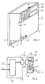
- Figure 1 shows a counter 1 in a spatial representation. It can be any counter for counting one any amount of energy, e.g. B. a flow rate one Amount of heat or electrical energy. present is purely an example of a version for counting electrical Referred to energy.
- the counter 1 has a housing 3, which has a base part 5 and comprises a housing cover 7.
- the housing cover 7 is there for example by means of fasteners, not shown, z. B. screws or a clamping device with the bottom part 5 connectable.
- the housing cover 7 has an opening 9 through which a tab 11 of the bottom part 5 passes is. On this tab 11, as shown, a Calibration seal 13 are attached so that unauthorized opening of the housing 3 can be recognized.
- a display module 15 is arranged outside the housing cover 7. This can be done in different ways on the housing cover 7 be arranged. In the present it is in one Recess 17 arranged together with a locking handle 18th serves as a holding device for the display module 15.
- the display module 15 has a display 19 as a display element which, for example, is designed as an LCD display element can be.
- the display module 15 comprises on the front a first solar cell 21.
- On the closer function of the Display module 15 with its elements in connection with a not shown, arranged in the housing 3 Counting device is explained in more detail below with reference to FIG received.
- the counter 1 When the counter 1 is designed as an electricity meter this as shown on a terminal block 23 to which the signals required for measurement can be connected.
- FIG. 2 shows the counter 1 in a block diagram.
- Counter 25 arranged, for example, a microprocessor, Analog / digital converter or digital signal processors may include.
- the Counting device 25 On the input side, the Counting device 25 the required measured quantities, in the present case the signals S1 and S2, purely by way of example.
- the signals S1 and S2 can, for. B. electricity and Be tension.
- these signals could for example, a flow rate and a temperature his.
- the measured amount of energy is sent to an energy signal S3 optical interface 27 passed, which is an information transmission from the counter 25 to the display module 15 allowed.
- the optical interface 27 has on the housing side a transmission means, in particular a light-emitting diode 29, on the to a receiving means arranged on the display module 15, in particular a second solar cell 31 is aligned.
- the second solar cell 31 has a memory on the output side 33 connected. This means that those contained in signal S3 Information, especially about the amount of energy consumed, can be read into the memory 33.
- This arrangement has another function.
- the signal S3 via the light-emitting diode 29 to the second solar cell 31 transmitted information is transmitted energy.
- this energy is used for this, at least Memory 33 to operate.
- the second solar cell 31 is for this connected to a power supply device 32 which optionally, as indicated, an energy store, e.g. one Capacitor or a battery.
- a first solar cell 21 arranged with an external Light source e.g. B. ambient light (light rays L), or an additional light, especially a flashlight, can be supplied with energy.
- an external Light source e.g. B. ambient light (light rays L)
- an additional light especially a flashlight
- the energy distribution from the first solar cell 21 to the storage 33 and the display 19 and / or optionally further active processing facilities within the display module 15 is carried out by the energy supply device 32 like a power supply. It has a corresponding one electrical circuit, e.g. with decoupling diodes for the solar cells, on.
- FIG. 2 clearly shows, there is only one signal direction here from the housing 3 to the display module 15.
- the Counting device 25 is protected without retroactive effects.
- the display module 15 can thus be used in the event of repair or maintenance can be easily exchanged. If necessary is for reading the display module 15 even easily removable, what that Reading considerably simplified. In this case, if necessary a backup battery or other electrical Memory for operating the memory 33 - as already indicated - be provided.
- the display module 15 also have a keypad that can be called up or to activate various reading functions within of the display module 15 is used.
- a keypad that can be called up or to activate various reading functions within of the display module 15 is used.
- it is on call different energy values, e.g. B. maximum or minimum values, Reactive or active power and a reset function intended to reset the memory 33.
Landscapes
- Physics & Mathematics (AREA)
- General Physics & Mathematics (AREA)
- Engineering & Computer Science (AREA)
- Power Engineering (AREA)
- Arrangements For Transmission Of Measured Signals (AREA)
- Devices For Indicating Variable Information By Combining Individual Elements (AREA)
Claims (6)
- Compteur (1) ayant un boítier (3) qui peut être plombé et dans lequel est disposé un dispositif (25) compteur et comprenant un module (15) d'affichage qui est disposé à l'extérieur du boítier (3), caractérisé en ce qu'il est monté entre le module (15) d'affichage et le dispositif (25) compteur une interface (27) optique et en ce que l'interface optique sert au moins en partie à alimenter le module (15) d'affichage en énergie.
- Compteur suivant la revendication 1, dans lequel l'alimentation en énergie alimente une mémoire (33) du module (15) d'affichage.
- Compteur suivant la revendication 1 ou 2, dans lequel le module (15) d'affichage comprend une première pile (21) solaire au moins pour l'alimentation en énergie de l'affichage (19) du module (15) d'affichage, la première pile (21) solaire pouvant être alimentée en lumière par une source extérieure de lumière.
- Compteur suivant la revendication 3, dans lequel l'interface (27) optique comprend, du côté du boítier, une diode (29) électroluminescente et, du côté du module d'affichage, une deuxième (31) solaire, la deuxième pile (31) solaire étant disposée sur un côté du module (15) d'affichage qui est tourné vers le boítier (3) et la première pile (21) solaire étant disposée d'un côté du module (15) d'affichage qui est éloigné du boítier (3).
- Compteur suivant l'une des revendications 1 à 4, dans lequel le boítier (3) comporte un dispositif de maintien destiné à la réception du module (15) d'affichage.
- Compteur suivant l'une des revendications 1 à 5, dans lequel le dispositif (25) compteur sert à compter de l'énergie électrique, un débit, une quantité de chaleur ou une autre quantité d'énergie.
Applications Claiming Priority (3)
| Application Number | Priority Date | Filing Date | Title |
|---|---|---|---|
| DE19734892 | 1997-08-12 | ||
| DE19734892 | 1997-08-12 | ||
| PCT/DE1998/002311 WO1999008118A1 (fr) | 1997-08-12 | 1998-08-11 | Compteur |
Publications (2)
| Publication Number | Publication Date |
|---|---|
| EP1004028A1 EP1004028A1 (fr) | 2000-05-31 |
| EP1004028B1 true EP1004028B1 (fr) | 2002-05-08 |
Family
ID=7838733
Family Applications (1)
| Application Number | Title | Priority Date | Filing Date |
|---|---|---|---|
| EP98948769A Expired - Lifetime EP1004028B1 (fr) | 1997-08-12 | 1998-08-11 | Compteur |
Country Status (3)
| Country | Link |
|---|---|
| EP (1) | EP1004028B1 (fr) |
| DE (1) | DE59804072D1 (fr) |
| WO (1) | WO1999008118A1 (fr) |
Families Citing this family (1)
| Publication number | Priority date | Publication date | Assignee | Title |
|---|---|---|---|---|
| US20070067119A1 (en) * | 2005-09-16 | 2007-03-22 | Power Measurement Ltd. | Rack-mounted power meter having removable metering options module |
Family Cites Families (4)
| Publication number | Priority date | Publication date | Assignee | Title |
|---|---|---|---|---|
| US4887312A (en) * | 1987-09-14 | 1989-12-12 | Siemens Aktiengesellschaft | Method and apparatus for transmission of optical data between two electrically separated transmitting receiving units |
| DE4139011A1 (de) * | 1990-11-27 | 1992-06-04 | Jatco Corp | Speichereinrichtung fuer steuereinheit eines kraftfahrzeuges |
| DE4107452C1 (fr) * | 1991-03-08 | 1992-07-23 | Orga Kartensysteme Gmbh, 6072 Dreieich, De | |
| DE59601752D1 (de) * | 1995-07-07 | 1999-06-02 | Ind Technik Froeschl Gmbh | Elektrizitätszähler |
-
1998
- 1998-08-11 EP EP98948769A patent/EP1004028B1/fr not_active Expired - Lifetime
- 1998-08-11 WO PCT/DE1998/002311 patent/WO1999008118A1/fr not_active Ceased
- 1998-08-11 DE DE59804072T patent/DE59804072D1/de not_active Expired - Fee Related
Also Published As
| Publication number | Publication date |
|---|---|
| WO1999008118A1 (fr) | 1999-02-18 |
| DE59804072D1 (de) | 2002-06-13 |
| EP1004028A1 (fr) | 2000-05-31 |
Similar Documents
| Publication | Publication Date | Title |
|---|---|---|
| DE69323094T2 (de) | System zur erfassung und verwaltung von glukosetestdaten | |
| DE2911800A1 (de) | Programmierbares wechselstrom-energiemessgeraet mit strahlungsempfindlicher externer datenschnittstelle | |
| DE60220842T2 (de) | System zur Fernablesung und Steuerung von elektrischem Energieverbrauch | |
| DE69231869T2 (de) | Verfahren und Gerät zur Prüfung elektronischer Elektrizitätszähler | |
| DE102009008125B4 (de) | Modulares, erweiterbares und einen zugangsgeschützten Bereich aufweisendes Messgerät | |
| EP1506389A1 (fr) | Dispositif d'analyse en ligne | |
| DE3716019A1 (de) | Einrichtung zur erfassung, speicherung und/oder beeinflussung von verbrauchszaehlern | |
| DE19527702A1 (de) | Meßdatenverarbeitungscomputer für Durchlaufmengen- oder Wärmemengenmeßgeräte | |
| DE69014516T2 (de) | System zur Abgabe von Verbrauchsmitteln. | |
| CH673164A5 (en) | Operating data recording system with portable induct terminals - deposited in stationary data evaluation device to allow transfer of entered data | |
| EP0809835B1 (fr) | Systeme de saisie et d'evaluation de donnees relatives au temps et/ou au service | |
| DE3714072A1 (de) | Messgeraet | |
| EP1004028B1 (fr) | Compteur | |
| EP1035513B1 (fr) | Module de sécurité avec signalisation de l'état | |
| DE2613112B2 (de) | Elektronischer Maximumzähler | |
| DE19802462C2 (de) | Einrichtung für die chemische Analyse | |
| DE19603942A1 (de) | Datenerfassungsvorrichtung | |
| EP0752589B2 (fr) | Compteur électrique | |
| DE9420378U1 (de) | Anlage zur Meßwerterfassung und Anzeige, insbesondere Wägeanlage | |
| DE19922603A1 (de) | Verfahren und Vorrichtung zum Fernablesen eines Verbrauchszählers | |
| DE4496199C1 (de) | Vorrichtung zum Zählen und Anzeigen von Impulsen | |
| WO1986004994A1 (fr) | Appareil tarifaire incorpore dans le boitier d'un compteur electrique | |
| DE2944660A1 (de) | Elektrizitaetszaehler fuer zeitabhaengige anwendung unterschiedlicher tarife | |
| DE3410003A1 (de) | Leistungstarifanzeigegeraet | |
| DE19937821A1 (de) | Elektronisches Meßgerät |
Legal Events
| Date | Code | Title | Description |
|---|---|---|---|
| PUAI | Public reference made under article 153(3) epc to a published international application that has entered the european phase |
Free format text: ORIGINAL CODE: 0009012 |
|
| 17P | Request for examination filed |
Effective date: 20000131 |
|
| AK | Designated contracting states |
Kind code of ref document: A1 Designated state(s): CH DE FR GB LI |
|
| GRAG | Despatch of communication of intention to grant |
Free format text: ORIGINAL CODE: EPIDOS AGRA |
|
| 17Q | First examination report despatched |
Effective date: 20010924 |
|
| GRAG | Despatch of communication of intention to grant |
Free format text: ORIGINAL CODE: EPIDOS AGRA |
|
| GRAH | Despatch of communication of intention to grant a patent |
Free format text: ORIGINAL CODE: EPIDOS IGRA |
|
| REG | Reference to a national code |
Ref country code: GB Ref legal event code: IF02 |
|
| GRAH | Despatch of communication of intention to grant a patent |
Free format text: ORIGINAL CODE: EPIDOS IGRA |
|
| GRAA | (expected) grant |
Free format text: ORIGINAL CODE: 0009210 |
|
| AK | Designated contracting states |
Kind code of ref document: B1 Designated state(s): CH DE FR GB LI |
|
| PG25 | Lapsed in a contracting state [announced via postgrant information from national office to epo] |
Ref country code: GB Free format text: LAPSE BECAUSE OF FAILURE TO SUBMIT A TRANSLATION OF THE DESCRIPTION OR TO PAY THE FEE WITHIN THE PRESCRIBED TIME-LIMIT Effective date: 20020508 Ref country code: FR Free format text: LAPSE BECAUSE OF FAILURE TO SUBMIT A TRANSLATION OF THE DESCRIPTION OR TO PAY THE FEE WITHIN THE PRESCRIBED TIME-LIMIT Effective date: 20020508 |
|
| REG | Reference to a national code |
Ref country code: CH Ref legal event code: NV Representative=s name: SIEMENS SCHWEIZ AG Ref country code: CH Ref legal event code: EP |
|
| REF | Corresponds to: |
Ref document number: 59804072 Country of ref document: DE Date of ref document: 20020613 |
|
| PGFP | Annual fee paid to national office [announced via postgrant information from national office to epo] |
Ref country code: DE Payment date: 20021021 Year of fee payment: 5 |
|
| GBV | Gb: ep patent (uk) treated as always having been void in accordance with gb section 77(7)/1977 [no translation filed] |
Effective date: 20020508 |
|
| PGFP | Annual fee paid to national office [announced via postgrant information from national office to epo] |
Ref country code: CH Payment date: 20021108 Year of fee payment: 5 |
|
| EN | Fr: translation not filed | ||
| PLBE | No opposition filed within time limit |
Free format text: ORIGINAL CODE: 0009261 |
|
| STAA | Information on the status of an ep patent application or granted ep patent |
Free format text: STATUS: NO OPPOSITION FILED WITHIN TIME LIMIT |
|
| 26N | No opposition filed |
Effective date: 20030211 |
|
| PG25 | Lapsed in a contracting state [announced via postgrant information from national office to epo] |
Ref country code: LI Free format text: LAPSE BECAUSE OF NON-PAYMENT OF DUE FEES Effective date: 20030831 Ref country code: CH Free format text: LAPSE BECAUSE OF NON-PAYMENT OF DUE FEES Effective date: 20030831 |
|
| PG25 | Lapsed in a contracting state [announced via postgrant information from national office to epo] |
Ref country code: DE Free format text: LAPSE BECAUSE OF NON-PAYMENT OF DUE FEES Effective date: 20040302 |
|
| REG | Reference to a national code |
Ref country code: CH Ref legal event code: PL |