EP1004036B1 - Verfahren und vorrichtung zur abstands- und geschwindigkeitsmessung - Google Patents
Verfahren und vorrichtung zur abstands- und geschwindigkeitsmessung Download PDFInfo
- Publication number
- EP1004036B1 EP1004036B1 EP98947346A EP98947346A EP1004036B1 EP 1004036 B1 EP1004036 B1 EP 1004036B1 EP 98947346 A EP98947346 A EP 98947346A EP 98947346 A EP98947346 A EP 98947346A EP 1004036 B1 EP1004036 B1 EP 1004036B1
- Authority
- EP
- European Patent Office
- Prior art keywords
- measurement
- signal
- frequencies
- matrix
- calculated
- Prior art date
- Legal status (The legal status is an assumption and is not a legal conclusion. Google has not performed a legal analysis and makes no representation as to the accuracy of the status listed.)
- Expired - Lifetime
Links
- 238000000034 method Methods 0.000 title claims description 32
- 239000011159 matrix material Substances 0.000 claims description 41
- 238000005259 measurement Methods 0.000 claims description 38
- 238000004458 analytical method Methods 0.000 claims description 9
- 238000011156 evaluation Methods 0.000 claims description 9
- 230000005540 biological transmission Effects 0.000 claims description 8
- 238000012545 processing Methods 0.000 claims description 5
- 230000000694 effects Effects 0.000 claims description 4
- 230000007704 transition Effects 0.000 claims description 4
- 238000001228 spectrum Methods 0.000 claims description 3
- 230000008707 rearrangement Effects 0.000 claims 2
- 238000005070 sampling Methods 0.000 claims 2
- 238000000354 decomposition reaction Methods 0.000 description 5
- 238000004364 calculation method Methods 0.000 description 4
- 230000009466 transformation Effects 0.000 description 3
- 238000012937 correction Methods 0.000 description 2
- 230000001419 dependent effect Effects 0.000 description 2
- 238000005516 engineering process Methods 0.000 description 2
- 238000000844 transformation Methods 0.000 description 2
- 230000004304 visual acuity Effects 0.000 description 2
- 241001123248 Arma Species 0.000 description 1
- 238000007476 Maximum Likelihood Methods 0.000 description 1
- 238000013459 approach Methods 0.000 description 1
- 239000004566 building material Substances 0.000 description 1
- 230000008859 change Effects 0.000 description 1
- 230000003111 delayed effect Effects 0.000 description 1
- 238000009795 derivation Methods 0.000 description 1
- 238000010586 diagram Methods 0.000 description 1
- 230000002349 favourable effect Effects 0.000 description 1
- 230000008569 process Effects 0.000 description 1
- 230000003595 spectral effect Effects 0.000 description 1
- 238000010183 spectrum analysis Methods 0.000 description 1
- 238000010897 surface acoustic wave method Methods 0.000 description 1
- 230000009897 systematic effect Effects 0.000 description 1
- 238000012360 testing method Methods 0.000 description 1
- 238000002604 ultrasonography Methods 0.000 description 1
Images

Classifications
-
- G—PHYSICS
- G01—MEASURING; TESTING
- G01S—RADIO DIRECTION-FINDING; RADIO NAVIGATION; DETERMINING DISTANCE OR VELOCITY BY USE OF RADIO WAVES; LOCATING OR PRESENCE-DETECTING BY USE OF THE REFLECTION OR RERADIATION OF RADIO WAVES; ANALOGOUS ARRANGEMENTS USING OTHER WAVES
- G01S7/00—Details of systems according to groups G01S13/00, G01S15/00, G01S17/00
- G01S7/02—Details of systems according to groups G01S13/00, G01S15/00, G01S17/00 of systems according to group G01S13/00
- G01S7/35—Details of non-pulse systems
- G01S7/352—Receivers
-
- G—PHYSICS
- G01—MEASURING; TESTING
- G01S—RADIO DIRECTION-FINDING; RADIO NAVIGATION; DETERMINING DISTANCE OR VELOCITY BY USE OF RADIO WAVES; LOCATING OR PRESENCE-DETECTING BY USE OF THE REFLECTION OR RERADIATION OF RADIO WAVES; ANALOGOUS ARRANGEMENTS USING OTHER WAVES
- G01S13/00—Systems using the reflection or reradiation of radio waves, e.g. radar systems; Analogous systems using reflection or reradiation of waves whose nature or wavelength is irrelevant or unspecified
- G01S13/02—Systems using reflection of radio waves, e.g. primary radar systems; Analogous systems
- G01S13/06—Systems determining position data of a target
- G01S13/08—Systems for measuring distance only
- G01S13/32—Systems for measuring distance only using transmission of continuous waves, whether amplitude-, frequency-, or phase-modulated, or unmodulated
- G01S13/34—Systems for measuring distance only using transmission of continuous waves, whether amplitude-, frequency-, or phase-modulated, or unmodulated using transmission of continuous, frequency-modulated waves while heterodyning the received signal, or a signal derived therefrom, with a locally-generated signal related to the contemporaneously transmitted signal
-
- G—PHYSICS
- G01—MEASURING; TESTING
- G01S—RADIO DIRECTION-FINDING; RADIO NAVIGATION; DETERMINING DISTANCE OR VELOCITY BY USE OF RADIO WAVES; LOCATING OR PRESENCE-DETECTING BY USE OF THE REFLECTION OR RERADIATION OF RADIO WAVES; ANALOGOUS ARRANGEMENTS USING OTHER WAVES
- G01S13/00—Systems using the reflection or reradiation of radio waves, e.g. radar systems; Analogous systems using reflection or reradiation of waves whose nature or wavelength is irrelevant or unspecified
- G01S13/02—Systems using reflection of radio waves, e.g. primary radar systems; Analogous systems
- G01S13/50—Systems of measurement based on relative movement of target
- G01S13/58—Velocity or trajectory determination systems; Sense-of-movement determination systems
- G01S13/583—Velocity or trajectory determination systems; Sense-of-movement determination systems using transmission of continuous unmodulated waves, amplitude-, frequency-, or phase-modulated waves and based upon the Doppler effect resulting from movement of targets
- G01S13/584—Velocity or trajectory determination systems; Sense-of-movement determination systems using transmission of continuous unmodulated waves, amplitude-, frequency-, or phase-modulated waves and based upon the Doppler effect resulting from movement of targets adapted for simultaneous range and velocity measurements
-
- G—PHYSICS
- G01—MEASURING; TESTING
- G01S—RADIO DIRECTION-FINDING; RADIO NAVIGATION; DETERMINING DISTANCE OR VELOCITY BY USE OF RADIO WAVES; LOCATING OR PRESENCE-DETECTING BY USE OF THE REFLECTION OR RERADIATION OF RADIO WAVES; ANALOGOUS ARRANGEMENTS USING OTHER WAVES
- G01S7/00—Details of systems according to groups G01S13/00, G01S15/00, G01S17/00
- G01S7/02—Details of systems according to groups G01S13/00, G01S15/00, G01S17/00 of systems according to group G01S13/00
- G01S7/35—Details of non-pulse systems
- G01S7/352—Receivers
- G01S7/356—Receivers involving particularities of FFT processing
Definitions
- microwaves, Light waves or ultrasound are used for this.
- Sensors have a variety of uses, for example in industrial automation, in automotive engineering and in the household.
- Radar sensors are used after the FMCW principle (frequency modulated continuous wave).
- the figure shows a typical circuit diagram of an FMCW sensor (see also AG Stove: "Linear FMCW radar techniques", IEE Proc.-F 139, 343-350 (1992)).
- the signal source is a frequency modulated oscillator (MO).
- the frequency of this oscillator is detuned via a control unit.
- the sensor emits the transmission signal s (t) via the transceiver unit SEE and receives a reception signal r (t) which is time-delayed in accordance with the transit time to the test object.
- the transmission and reception signals are separated, for example, by a transmission and reception switch (SEW) (such as a circulator or a directional coupler).
- SEW transmission and reception switch
- separate antennas can be used for sending and receiving (so-called bistatic arrangement).
- the received signal r (t) can be mixed in a second mixer MI2 with the transmit signal phase-shifted by ⁇ / 2 in a phase shifter PH and then filtered in a second low-pass filter TP2.
- the evaluation unit AE is preferably constructed with a digital signal processor to which the measurement signal digitized by means of analog-digital converters A / D is supplied as the real part cosine and imaginary part sine of the complex signal.
- the frequency modulation of the transmitted signal is generally linear in time (see HD Griffiths: "The Effect of Phase and Amplitude Errors in FM Radar", IEEE Colloquium on High Time-Bandwidth Product Waveforms in Radar and Sonar, London, UK, May 1st, 1991, pp. 9 / 1-9 / 5).
- DE 195 33 124 describes a method in which Frequency modulation error using a delay line be detected and corrected.
- a delay line is shown, the one Delay element ⁇ (preferably a surface acoustic wave device) and another mixer RMI.
- Another low-pass filter TP3 is preferably connected downstream.
- the delayed signal is in the further mixer RMI mixed with the current transmission signal to form a reference signal.
- a correction signal is in the evaluation unit AE calculated, which can also be used via a programmable Control unit a correction of the frequency modulation make.
- a sensor system is shown where the transmit frequency before the delay in a mixer ZFMI mixed to a lower intermediate frequency becomes. For this, the local oscillator LO is provided, the one delivers lower frequency than the signal source MO.
- the sensor signal mess (t) of an FMCW radar sensor from a superposition of discrete sine waves, whose frequencies are the quantities to be measured (distance, transit time, Speed).
- a level sensor e.g. the frequency of the sensor signal is proportional the difference between container and filling height; at The presence of several measurement objects occurs accordingly Frequencies on. If an object moves, it becomes distance-dependent Frequency of the sensor signal an additional Doppler frequency additively superimposed. In the special case of a CW radar sensor only this Doppler frequency is detected, the represents the object speed.
- the frequencies f k and their number p, as well as the associated (complex) amplitudes c k are to be determined from the finite data set [x (1), x (2), ..., x (N)].
- Np of such linear equation pairs (2a, 2b) can be set up with the given data set [x (1), x (2), ..., x (N)], ie 2 (Np) equations; and from this the a (k) can be determined.
- the system of equations (2a, 2b) consists of more equations than unknowns a (k).
- the equations are formed a generally over-determined linear system of equations for the p amplitudes c k , which is solved in a third step by the LS method (see above), as a result of which the interference with the R (n) components is again averaged.
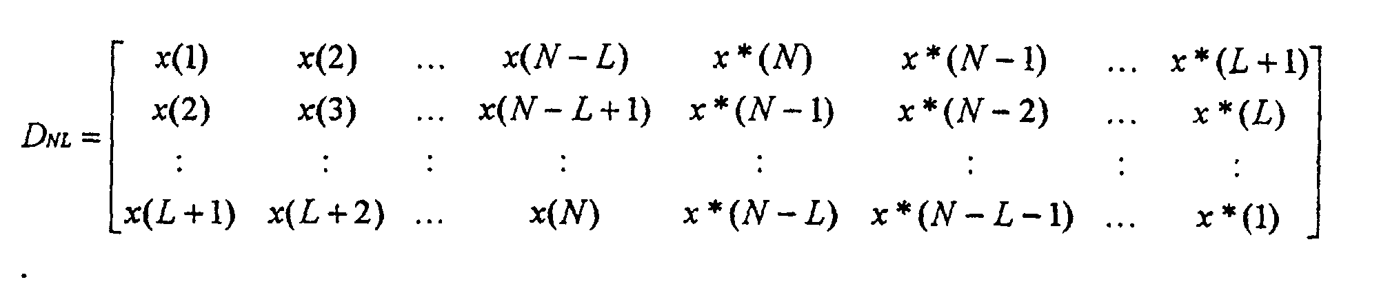
- the measurement data are arranged in a matrix, a so-called double Hankel matrix.
- Each column of this matrix supplies one of the equations (6a, 6b) multiplied by the row vector [a (L), a (L-1), ..., a (0)].
- the matrix D NL would have the rank (rank) p ( ⁇ L).
- D NL generally has the maximum rank (2N-2L or L + 1) and only approximately has the smaller rank p.
- a matrix is determined from D NL , which has the rank p and an approximation of D NL is in the sense of the LS method known from the literature (smallest sum of squares of the deviations) .
- the diagonal elements S kk (the so-called singular values of D NL ) of this "diagonal matrix" S are arranged in size according to S 11 ⁇ S 22 ⁇ ... ⁇ S LL ⁇ 0.
- the number of diagonal elements other than 0 is equal to the rank of D NL . If the signal x (n) contained no noise, ie only p exponential vibrations, then exactly p ( ⁇ L) diagonal elements, the so-called “principal components” (PC), would be different from zero, the rest would be zero. However, if there is noise, the remaining diagonal elements are generally ⁇ 0, but small compared to the principal components. They are set to approximately zero ("PC method"). This gives an approximation S _ of S.
- the product of the first two factors U * S _ can be factored according to where h is a row vector of length p and F is the "state transition matrix" with p rows and p columns.
- the eigenvalues (eigenvalues) and eigenvectors (eigenvectors) of F provide the signal frequencies f k and the associated amplitudes c k without the FBLP coefficients a (k) having to be calculated.
- the f k are the frequencies sought.
- the object of the present invention is an improved Specify procedure by which the distances and / or speeds of several objects measured exactly at the same time can be.
- a suitable for this procedure Device can be specified.
- a measurement signal as a superposition of different frequencies detected and the evaluation of this measurement signal with the help a high-resolution frequency analysis. It will discretely sampled, at equidistant time intervals mutually recorded values of the measurement signal as a data matrix in Formed a double Hankel matrix and thus one SVD (Singular Value Decomposition) as described at the beginning carried out. From the PC (Principal Components) of the received Diagonal matrix S and from the associated sub-matrices of the unitary transformation matrices U and possibly V then Estimated values for the signal frequencies and the associated ones Amplitudes calculated.
- PC Principal Components
- the method can preferably be used in a sensor system are constructed in principle as explained at the beginning is.
- a mixer another suitable one can be used Device provided for processing a measurement signal his.
- So-called IQ mixers can be used to generate a complex-value measurement signal are used.
- the measurement signal mess (t) is preferably largely from Frequency modulation errors occurring in the arrangement free what z. B. with a delay line for generation a reference signal can happen. So that with the Frequency analysis used according to the method of the invention is good Provides measurement results, must occur in the measurement signal Frequencies kept constant over time if possible become.
- a sensor system is advantageous with a technical concept that is a measurement signal from the outset with, apart from noise, constant frequencies supplies. Measured values are stored in the evaluation unit AE and thus performed calculations for frequency analysis. This is preferably done in a digital signal processor with those previously digitized using an analog-digital converter Values.
- the coefficient matrix (data matrix) of the a (k) to be determined is broken down as described in the introduction into U * S * V H with two unitary matrices U and V and a (only in special cases square) "diagonal matrix" S with non-negative diagonal elements.
- D _NL U * S _ * V H is determined with the approximation S _ , in which the small diagonal elements of S are set to 0.
- the number p of the frequencies is also determined, so that the number of measured variables which, for. B. is given by the initially unknown number of available objects to be inferred.
- the condition according to which p is determined can be adapted to the quantities to be measured or to accompanying circumstances of the measurement.
- a criterion for determining which of the diagonal elements of S are set to zero is e.g. B. the difference of successive values of the diagonal elements. If, for example, this difference becomes less than 2 dB and remains so small, the diagonal elements which differ from one another by less than 2 dB are set to zero.
- the sizes c k are z in a third step. B. determined by LS method (Least Squares).
Landscapes
- Engineering & Computer Science (AREA)
- Radar, Positioning & Navigation (AREA)
- Remote Sensing (AREA)
- Computer Networks & Wireless Communication (AREA)
- Physics & Mathematics (AREA)
- General Physics & Mathematics (AREA)
- Radar Systems Or Details Thereof (AREA)
Description



(2b) analogen Gleichungen lauten dann


A = U * S_ * Q und B = Q-1 * VH. Dann ergibt sich für jedes k die Amplitude ck durch Multiplikation des in der k-ten Spalte stehenden Elementes der ersten Zeile von A mit dem in der k-ten Zeile stehenden Element der ersten Spalte von B und Division durch den zugehörigen Eigenwert von F gemäß


[a(L), a(L-1), ..., a(0)] * D_NL = 0 mit dieser Matrix D_NL als Minimum-Norm-Lösung berechnet.

A = U * S_* Q und die erste Spalte von B = Q-1 * VH berechnet. Dann wird ck gemäß ck = A1k ·Bk1/exp(2π·i·fk) berechnet.
Claims (6)
- Verfahren zur Abstands- und Geschwindigkeitsmessung, bei demSignale, die sich in Wellenform ausbreiten, ausgesendet und nach Reflexion an Meßobjekten als Meßsignale aufgenommen werden, so daß diese Meßsignale eine Frequenzmodulation aufweisen, die von dem Wert oder den Werten der zu messenden Größe oder Größen abhängt, undeine Analyse des Frequenzspektrums dieser Meßsignale anhand einer zuvor festgelegten Anzahl von Meßwerten erfolgt, indema) in einem ersten Schritt diese Anzahl von Meßwerten durch Abtasten des Meßsignales in äquidistanten Zeitabständen erfaßt und in vorgegebener Reihenfolge gespeichert wird,b) in einem zweiten Schritt bis auf äquivalente Umformungen eine Datenmatrix, in der die Meßwerte chronologisch als doppelte Hankel-Matrix angeordnet sind, nach einem SVD-Verfahren diagonalisiert wird,c) in einem dritten Schritt eine Näherung der diagonalisierten Datenmatrix bestimmt wird, indem Diagonalelemente ab einer vorgegebenen oder aus der Verteilung der Diagonalelemente errechneten Grenze gleich null gesetzt werden, undd) in einem vierten Schritt aus den übrigen Diagonalelementen (principle components) Frequenzen berechnet werden.
- Verfahren nach Anspruch 1, bei dem
in dem vierten Schritt FBLP-Koeffizienten a(m) als Minimum-Norm-Lösung berechnet werden und die Frequenzen fk aus den Nullstellen zk = exp(2π·i·fk) des Polynomsberechnet werden.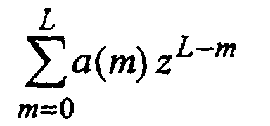
- Verfahren nach Anspruch 1, bei dem
in dem vierten Schritt zu der in dem dritten Schritt berechneten Näherung eine State-Transition-Matrix berechnet wird und die Frequenzen aus den Eigenwerten Λkk = exp(2π·i·fk) dieser State-Transistion-Matrix berechnet werden. - Vorrichtung zur Abstands- und Geschwindigkeitsmessung,bei der eine Signalquelle (MO) zur Erzeugung von Signalen, die sich wellenförmig ausbreiten, vorhanden ist,bei der eine Sende- und Empfangseinrichtung (SEE) vorhanden ist, die dafür vorgesehen ist, Signale auszusenden und von Meßobjekten reflektierte Signale zu empfangen,bei der eine Einrichtung zur Aufbereitung eines Meßsignales vorhanden ist,bei der Mittel vorgesehen sind, mit denen bewirkt wird, daß das Meßsignal zeitlich stabile Frequenzen aufweist, aus denen eine zu messende Größe oder mehrere zu messende Größen bestimmt werden können, undbei der eine Auswerteeinrichtung (AE) vorhanden ist, die dafür vorgesehen ist,a) in einem ersten Schritt eine zuvor festgelegte Anzahl von Meßwerten durch Abtasten des Meßsignales in äquidistanten Zeitabständen zu erfassen und in vorgegebener Reihenfolge zu speichern,b) in einem zweiten Schritt bis auf äquivalente Umformungen eine Datenmatrix, in der die Meßwerte chronologisch als doppelte Hankel-Matrix angeordnet sind, nach einem SVD-Verfahren zu diagonalisieren,c) in einem dritten Schritt eine Näherung der diagonalisierten Datenmatrix zu bestimmen, indem Diagonalelemente ab einer vorgegebenen oder aus der Verteilung der Diagonalelemente errechneten Grenze gleich null gesetzt werden, undd) in einem vierten Schritt aus den übrigen Diagonalelementen (principle components) Frequenzen zu berechnen.
- Vorrichtung nach Anspruch 4,
bei der die Mittel, mit denen bewirkt wird, daß das Meßsignal zeitlich stabile Frequenzen aufweist, umfasseneine Einrichtung zur Frequenzmodulation der von der Signalquelle erzeugten Signale undeine Mischeinrichtung (MI1; PH, MI2) zum Mischen eines empfangenen Signals mit einem aktuellen Sendesignal. - Vorrichtung nach Anspruch 5,
bei der die Mittel, mit denen bewirkt wird, daß das Meßsignal zeitlich stabile Frequenzen aufweist, weiter umfassen
eine Einrichtung zur Erzeugung eines Bezugssignales durch Mischen des von der Signalquelle erzeugten Signales mit einem dazu zeitlich verzögerten Signal.
Applications Claiming Priority (3)
| Application Number | Priority Date | Filing Date | Title |
|---|---|---|---|
| DE19736693 | 1997-08-22 | ||
| DE19736693 | 1997-08-22 | ||
| PCT/DE1998/002114 WO1999010757A1 (de) | 1997-08-22 | 1998-07-27 | Verfahren und vorrichtung zur abstands- und geschwindigkeitsmessung |
Publications (2)
| Publication Number | Publication Date |
|---|---|
| EP1004036A1 EP1004036A1 (de) | 2000-05-31 |
| EP1004036B1 true EP1004036B1 (de) | 2002-10-16 |
Family
ID=7839924
Family Applications (1)
| Application Number | Title | Priority Date | Filing Date |
|---|---|---|---|
| EP98947346A Expired - Lifetime EP1004036B1 (de) | 1997-08-22 | 1998-07-27 | Verfahren und vorrichtung zur abstands- und geschwindigkeitsmessung |
Country Status (4)
| Country | Link |
|---|---|
| US (1) | US6529794B1 (de) |
| EP (1) | EP1004036B1 (de) |
| DE (1) | DE59805991D1 (de) |
| WO (1) | WO1999010757A1 (de) |
Families Citing this family (11)
| Publication number | Priority date | Publication date | Assignee | Title |
|---|---|---|---|---|
| DE19925216C1 (de) * | 1999-06-01 | 2001-01-04 | Siemens Ag | Verfahren zur störsignalfreien Auswertung von Radarsignalen |
| DE19946161A1 (de) * | 1999-09-27 | 2001-04-26 | Siemens Ag | Verfahren zur Abstandsmessung |
| TW452884B (en) * | 1999-12-29 | 2001-09-01 | Winbond Electronics Corp | Frequency modulated endpoint detecting method and manufacturing apparatus for applying the method |
| DE102006011500A1 (de) * | 2006-03-14 | 2007-09-20 | Abb Patent Gmbh | Verfahren zum Betrieb eines Steuerungssystems eines verfahrenstechnischen Prozesses |
| US8543990B2 (en) * | 2007-05-14 | 2013-09-24 | Raytheon Company | Methods and apparatus for testing software with real-time source data from a projectile |
| EP2533069A1 (de) | 2011-06-10 | 2012-12-12 | Sony Corporation | Signalverarbeitungseinheit und -verfahren |
| KR101639119B1 (ko) * | 2014-06-13 | 2016-07-12 | 재단법인대구경북과학기술원 | 레이더 신호 처리 장치 및 방법 |
| CN108152855A (zh) * | 2017-12-14 | 2018-06-12 | 西南石油大学 | 一种基于eemd-svd的地震流体识别方法 |
| CN108415017B (zh) * | 2018-05-10 | 2021-07-30 | 北京航空航天大学 | 复杂目标雷达散射特性稀疏表征的一维增广状态空间方法 |
| JP7161230B2 (ja) * | 2020-11-09 | 2022-10-26 | 国立研究開発法人宇宙航空研究開発機構 | 距離計測装置、距離計測方法、及びプログラム |
| JP7112765B2 (ja) * | 2020-11-09 | 2022-08-04 | 国立研究開発法人宇宙航空研究開発機構 | 距離計測装置、距離計測方法、及びプログラム |
Family Cites Families (5)
| Publication number | Priority date | Publication date | Assignee | Title |
|---|---|---|---|---|
| DE59300252D1 (de) * | 1993-08-13 | 1995-07-13 | Siemens Ag | Verfahren zur hochauflösenden Spektralanalyse bei mehrkanaligen Beobachtungen. |
| US5917726A (en) * | 1993-11-18 | 1999-06-29 | Sensor Adaptive Machines, Inc. | Intelligent machining and manufacturing |
| JPH11512180A (ja) | 1995-09-07 | 1999-10-19 | シーメンス アクチエンゲゼルシヤフト | 距離測定装置 |
| US5959568A (en) * | 1996-06-26 | 1999-09-28 | Par Goverment Systems Corporation | Measuring distance |
| DE59711570D1 (de) * | 1996-12-21 | 2004-06-03 | Zeiss Carl | Verfahren zur Steuerung eines Koordinatenmessgerätes und Koordinatenmessgerät |
-
1998
- 1998-07-27 WO PCT/DE1998/002114 patent/WO1999010757A1/de not_active Ceased
- 1998-07-27 EP EP98947346A patent/EP1004036B1/de not_active Expired - Lifetime
- 1998-07-27 US US09/463,052 patent/US6529794B1/en not_active Expired - Fee Related
- 1998-07-27 DE DE59805991T patent/DE59805991D1/de not_active Expired - Lifetime
Also Published As
| Publication number | Publication date |
|---|---|
| US6529794B1 (en) | 2003-03-04 |
| DE59805991D1 (de) | 2002-11-21 |
| WO1999010757A1 (de) | 1999-03-04 |
| EP1004036A1 (de) | 2000-05-31 |
Similar Documents
| Publication | Publication Date | Title |
|---|---|---|
| EP1984707B1 (de) | Paarweise zf-abtastung für puls-laufzeit-füllstandsensoren | |
| EP3418700B1 (de) | Füllstandradargerät mit automatisierter frequenzanpassung | |
| DE69218331T2 (de) | Rauschpegelverringerung in Radargeräten für Streuziele | |
| DE102008014918B4 (de) | Verfahren zum Erfassen einer Interferenz in einem Radarsystem und Radar, das das gleiche verwendet | |
| DE102007035368B4 (de) | Radarvorrichtung | |
| DE4244608C2 (de) | Mittels eines Computers durchgeführtes Radarverfahren zur Messung von Abständen und Relativgeschwindigkeiten zwischen einem Fahrzeug und vor ihm befindlichen Hindernissen | |
| DE102018120685B4 (de) | Mehrfachauflösungs-dopplerverarbeitung | |
| EP1324067B1 (de) | Verfahren und Schaltungsanordnung zum Messen der Entfernung eines Gegenstandes | |
| DE102017128508B4 (de) | System und Verfahren zum Schätzen einer Geschwindigkeit eines Ziels mit einem linearen Frequenzmodulationsradar | |
| DE102018130214B4 (de) | TX Strahlformer im MIMO Radar | |
| EP3596499B1 (de) | Verfahren zum bestimmen eines abstandes und einer geschwindigkeit eines objektes | |
| DE3789830T3 (de) | Radargerät zur Messung der Entfernung zu einer Oberfläche. | |
| EP2417475A2 (de) | Radarsystem mit anordnungen und verfahren zur entkopplung von sende- und empfangssignalen sowie unterdrückung von störeinstrahlungen | |
| EP1004036B1 (de) | Verfahren und vorrichtung zur abstands- und geschwindigkeitsmessung | |
| EP2516973A2 (de) | Verfahren zur ermittlung und überwachung des füllstands eines mediums in einem behälter nach einem laufzeitmessverfahren | |
| EP1183503B1 (de) | Verfahren zur störsignalfreien auswertung von radarsignalen | |
| EP0965052B1 (de) | Verfahren zum betrieb eines sensorsystems und sensorsystem | |
| EP3467451B1 (de) | Verfahren und füllstandmessgerät zur bestimmung des füllstandes eines mediums mittels dauerstrich-radarmessung | |
| DE102023107806A1 (de) | Radarsystem und verfahren zum durchführen einer ankunftsrichtungs-schätzung | |
| DE102019216879B3 (de) | FMCW-Radarmessgerät | |
| EP2789996B1 (de) | Echokurvenbestimmung mit bereichsweise unterschiedlicher auflösung | |
| EP1877825B1 (de) | Verfahren und vorrichtung zur bestimmung eines abstands zu einem zielobjekt | |
| DE102024101465A1 (de) | Radardatenkomprimierung | |
| EP2577348B1 (de) | Verfahren und vorrichtung zum vermessen eines bodenprofils | |
| DE102024107887A1 (de) | Sende-/Empfangsgerät und Verfahren zum Charakterisieren eines Sende-/Empfangsgeräts |
Legal Events
| Date | Code | Title | Description |
|---|---|---|---|
| PUAI | Public reference made under article 153(3) epc to a published international application that has entered the european phase |
Free format text: ORIGINAL CODE: 0009012 |
|
| 17P | Request for examination filed |
Effective date: 20000218 |
|
| AK | Designated contracting states |
Kind code of ref document: A1 Designated state(s): DE FR GB NL SE |
|
| GRAG | Despatch of communication of intention to grant |
Free format text: ORIGINAL CODE: EPIDOS AGRA |
|
| 17Q | First examination report despatched |
Effective date: 20020321 |
|
| GRAG | Despatch of communication of intention to grant |
Free format text: ORIGINAL CODE: EPIDOS AGRA |
|
| GRAH | Despatch of communication of intention to grant a patent |
Free format text: ORIGINAL CODE: EPIDOS IGRA |
|
| GRAH | Despatch of communication of intention to grant a patent |
Free format text: ORIGINAL CODE: EPIDOS IGRA |
|
| GRAA | (expected) grant |
Free format text: ORIGINAL CODE: 0009210 |
|
| AK | Designated contracting states |
Kind code of ref document: B1 Designated state(s): DE FR GB NL SE |
|
| PG25 | Lapsed in a contracting state [announced via postgrant information from national office to epo] |
Ref country code: NL Free format text: LAPSE BECAUSE OF FAILURE TO SUBMIT A TRANSLATION OF THE DESCRIPTION OR TO PAY THE FEE WITHIN THE PRESCRIBED TIME-LIMIT Effective date: 20021016 |
|
| REG | Reference to a national code |
Ref country code: GB Ref legal event code: FG4D Free format text: NOT ENGLISH |
|
| REF | Corresponds to: |
Ref document number: 59805991 Country of ref document: DE Date of ref document: 20021121 |
|
| PG25 | Lapsed in a contracting state [announced via postgrant information from national office to epo] |
Ref country code: SE Free format text: LAPSE BECAUSE OF FAILURE TO SUBMIT A TRANSLATION OF THE DESCRIPTION OR TO PAY THE FEE WITHIN THE PRESCRIBED TIME-LIMIT Effective date: 20030116 |
|
| GBT | Gb: translation of ep patent filed (gb section 77(6)(a)/1977) |
Effective date: 20030122 |
|
| NLV1 | Nl: lapsed or annulled due to failure to fulfill the requirements of art. 29p and 29m of the patents act | ||
| ET | Fr: translation filed | ||
| PLBE | No opposition filed within time limit |
Free format text: ORIGINAL CODE: 0009261 |
|
| STAA | Information on the status of an ep patent application or granted ep patent |
Free format text: STATUS: NO OPPOSITION FILED WITHIN TIME LIMIT |
|
| 26N | No opposition filed |
Effective date: 20030717 |
|
| PGFP | Annual fee paid to national office [announced via postgrant information from national office to epo] |
Ref country code: GB Payment date: 20120709 Year of fee payment: 15 |
|
| PGFP | Annual fee paid to national office [announced via postgrant information from national office to epo] |
Ref country code: DE Payment date: 20120906 Year of fee payment: 15 Ref country code: FR Payment date: 20120802 Year of fee payment: 15 |
|
| GBPC | Gb: european patent ceased through non-payment of renewal fee |
Effective date: 20130727 |
|
| REG | Reference to a national code |
Ref country code: FR Ref legal event code: ST Effective date: 20140331 |
|
| PG25 | Lapsed in a contracting state [announced via postgrant information from national office to epo] |
Ref country code: DE Free format text: LAPSE BECAUSE OF NON-PAYMENT OF DUE FEES Effective date: 20140201 Ref country code: GB Free format text: LAPSE BECAUSE OF NON-PAYMENT OF DUE FEES Effective date: 20130727 |
|
| REG | Reference to a national code |
Ref country code: DE Ref legal event code: R119 Ref document number: 59805991 Country of ref document: DE Effective date: 20140201 |
|
| PG25 | Lapsed in a contracting state [announced via postgrant information from national office to epo] |
Ref country code: FR Free format text: LAPSE BECAUSE OF NON-PAYMENT OF DUE FEES Effective date: 20130731 |