EP1004059B1 - Procede pour la detection des connexions defectueuses d'un premier relais - Google Patents
Procede pour la detection des connexions defectueuses d'un premier relais Download PDFInfo
- Publication number
- EP1004059B1 EP1004059B1 EP98951166A EP98951166A EP1004059B1 EP 1004059 B1 EP1004059 B1 EP 1004059B1 EP 98951166 A EP98951166 A EP 98951166A EP 98951166 A EP98951166 A EP 98951166A EP 1004059 B1 EP1004059 B1 EP 1004059B1
- Authority
- EP
- European Patent Office
- Prior art keywords
- relay
- switching
- malfunction
- relays
- detected
- Prior art date
- Legal status (The legal status is an assumption and is not a legal conclusion. Google has not performed a legal analysis and makes no representation as to the accuracy of the status listed.)
- Expired - Lifetime
Links
- 238000000034 method Methods 0.000 title claims description 17
- 230000007257 malfunction Effects 0.000 title claims description 15
- 239000004065 semiconductor Substances 0.000 claims description 4
- 238000012360 testing method Methods 0.000 description 15
- 238000001514 detection method Methods 0.000 description 7
- 238000011161 development Methods 0.000 description 3
- 230000018109 developmental process Effects 0.000 description 3
- 238000005259 measurement Methods 0.000 description 3
- 238000010586 diagram Methods 0.000 description 2
- 238000012549 training Methods 0.000 description 2
- 230000004913 activation Effects 0.000 description 1
- 238000011156 evaluation Methods 0.000 description 1
- 239000003292 glue Substances 0.000 description 1
- 239000000203 mixture Substances 0.000 description 1
Images
Classifications
-
- G—PHYSICS
- G01—MEASURING; TESTING
- G01R—MEASURING ELECTRIC VARIABLES; MEASURING MAGNETIC VARIABLES
- G01R31/00—Arrangements for testing electric properties; Arrangements for locating electric faults; Arrangements for electrical testing characterised by what is being tested not provided for elsewhere
- G01R31/327—Testing of circuit interrupters, switches or circuit-breakers
- G01R31/3277—Testing of circuit interrupters, switches or circuit-breakers of low voltage devices, e.g. domestic or industrial devices, such as motor protections, relays, rotation switches
- G01R31/3278—Testing of circuit interrupters, switches or circuit-breakers of low voltage devices, e.g. domestic or industrial devices, such as motor protections, relays, rotation switches of relays, solenoids or reed switches
-
- H—ELECTRICITY
- H01—ELECTRIC ELEMENTS
- H01H—ELECTRIC SWITCHES; RELAYS; SELECTORS; EMERGENCY PROTECTIVE DEVICES
- H01H47/00—Circuit arrangements not adapted to a particular application of the relay and designed to obtain desired operating characteristics or to provide energising current
- H01H47/002—Monitoring or fail-safe circuits
Definitions
- the invention is based on a method for the detection of Incorrect switching of a first relay, its switching means in series is connected to a consumer that is in the preamble of Claim 1 defined genus.
- Switching means is connected in series with a consumer and each the connection according to the switching position in accordance with switching commands to the consumer interrupts or closes. Will a malfunction recognized, either with the switching commands or with the relays the motor consumer is supplied with potential so that it Start is prevented.
- the existing fault detection is based on the Detection of certain potentials and their quite complex ones Evaluation.
- the method according to the invention for the detection of faulty switching a first relay with the characteristic features of Claim 1 has the advantage of a simple and to provide a reliable solution where one Relay test using an electronic control unit implemented current measurement is carried out. In advantageous All relays can thus be controlled without one the actuators provided as consumers must be moved.
- a flowing through a circuit containing the switching means Current is detected and a malfunction of the relay, especially one Sticking of the switching means, recognized if the amperage is not the current strength to be expected according to the selected switching position equivalent.
- At least one second relay which has a first terminal the circuit by switching to at least two can put different potentials, and a second terminal of the Circuit lies on a first of the two potentials, provided, and according to the invention is a to the second relay Switching signal for connecting the first terminal to the second Potential is given and a switching signal is sent to the first relay given to open, and a failure of the two relays characteristic first error signal is emitted when a Current flow in the circuit is detected.
- Training is provided that a to the second relay Switching signal for switching the first terminal to the first Potential is given and a switching signal to the first relay is given to close if none in the previous step Fault was detected, and that a fault of the two relays characteristic error signal is emitted when a current flow in the Circuit is recognized.
- a third relay is provided, via which the second Terminal can be connected to one of the two potentials. According to an advantageous application of this Training according to the invention is achieved by switching the third Relay malfunction of the second relay and vice versa detected.
- Another advantageous embodiment of the invention is characterized by the use of a semiconductor switch Place at least one of the relays.
- the invention is based on one shown in the drawing Exemplary embodiment in the following description explained.
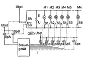
- the single figure shows schematically a block diagram an actuator control, shown using motors, in the the method according to the invention can be used advantageously.
- Fig. 1 the structure is schematic in a block diagram an actuator control shown, in which the actuators Motors M1, ..., Mx are. These motors M1, ..., Mx are over first relay 1 - X, consisting of the respective associated Relay coils Sp1 to Spx and those serving as switching means Relay contacts S1 to Sx, to which on lines 1 and 2 connected potentials switched.
- first relay 1 - X consisting of the respective associated Relay coils Sp1 to Spx and those serving as switching means Relay contacts S1 to Sx, to which on lines 1 and 2 connected potentials switched.
- a second relay A consisting of the relay coil SpA and the associated one Relay contact SA, a line 7 with two different Potentials, in the example shown either with GND or Ubat, connected. This different potential lies accordingly on one side of motors M1, ..., Mx.
- a line 6 with two different potentials in the example shown either with GND or Ubat. Accordingly, this is different potential on the second side of the motors M1, ..., Mx on. In this way, the clockwise or counterclockwise rotation of the Motors are determined.
- the control of the relay coils Sp1 to Spx, SpA and SpB are carried out by a control unit which corresponding switching signals or switching commands to the as Switching relay contacts in the corresponding Spend switch positions.
- the action of the relay coils on the associated relay contacts is by dotted lines indicated.
- Control device preferably provided a microcontroller and an in Device not shown in the figure for Total current measurement of all actuators, for example via one Shunt resistance in the line between the relay contacts SA / SB, line 5 and the GND potential, or a current measurement each path separately or a mixture of the two.
- the first test step involves driving the relay coil SpA and thus the closing of the relay contact SA after line 8.
- the potential Ubat on the motors is then on line 7 M1, ..., Mx on.
- the microcontroller measures a current, the greater than zero, generally: greater than an expected Setpoint, is and thus detects that one of the relays 1 to x, consisting of relay coils Sp1 to Spx and associated Relay contacts S1 to Sx, 'hangs in the closed position) Line 2).
- the control of the control unit for test purposes Relay takes place so long that the relays pull securely. On the other hand, the control is not maintained for so long received so that a malfunction of the relay Keep actuator movement as minimal as possible. In the The data of the used relays.
- the potential Ubat is then on line 6 on motors M1, ..., Mx.
- the microcontroller measures one Current greater than zero, generally: greater than an expected Setpoint, is and thus detects that one of the relays 1 to x, consisting of relay coils Sp1 to Spx and associated Relay contacts S1 to Sx, 'hangs in the closed position (against Line 2).
- a second test step is now that any Relay 1 to x, consisting of the associated relay coils Sp1 to Spx and the relay contacts S1 to Sx. Is now one of the relays A or B, consisting of a relay coil SpA / SpB and associated relay contact SA / SB, faulty closed, then the microcontroller measures a current that is larger is as zero. This detects that one of the relays A and B 'hangs' in position against the Ubat potential on line 8. After This second test step reverses the arrangement after the Control back to the basic position described above.
- the test regarding the 'hanging' of relays 1 - X in open Position or relays A and B against GND potential is via a minimum current detection in normal operation of the system, with the actuator control of the microcontroller does not measure any current. The error is then detected.
- test according to the method according to the invention can be carried out arbitrarily, for example after switching on the ignition in a motor vehicle or cyclically or in another appropriately.
- the result is available for diagnostic purposes Available and can in the functionality of the control unit be involved. For example, to ensure that the Detection of a relay malfunction no activation of the corresponding actuator more takes place.
- the method according to the invention can then advantageously also be used when using a semiconductor switch in place of at least one of the relays.
- Semiconductor switches can for example be a MOSFET transistor Find use.
- the method according to the invention enables a relay test without Movement of the actuators, provided the relays are OK. It also saves a lot of time because it doesn't all relays must be controlled for the test.
Landscapes
- Physics & Mathematics (AREA)
- General Physics & Mathematics (AREA)
- Testing Electric Properties And Detecting Electric Faults (AREA)
- Relay Circuits (AREA)
- Tests Of Electronic Circuits (AREA)
- Testing Of Short-Circuits, Discontinuities, Leakage, Or Incorrect Line Connections (AREA)
Claims (6)
- Procédé pour reconnaítre des branchements défectueux d'un premier relais travaillant en tension continue dont le moyen de commutation est branché en série avec un consommateur et qui, suivant la position de commutation, en fonction des ordres de commutation, interrompt ou établit la liaison avec le consommateur,
caractérisé en ce qu'
on détecte le courant traversant un circuit électrique comportant les moyens de commutation et on reconnaít un défaut de fonctionnement du premier relais, notamment le collage du moyen de commutation si l'intensité du courant ne correspond pas à l'intensité prévisible du courant suivant la position de commutation sélectionnée, en outre on a au moins un second relais également branché sur la tension continue, et
qui peut par commutation appliquer une première borne du circuit électrique sur au moins deux potentiels différents et une seconde borne du circuit électrique est reliée au premier des deux potentiels, et on émet au second relais un signal de commutation pour relier la première borne au second potentiel et au premier relais un signal de commutation pour ouvrir, et
un premier signal de défaut est émis, caractérisant un défaut des deux relais si l'on détecte un passage de courant dans le circuit de courant. - Procédé selon la revendication 1,
caractérisé en ce qu'
on émet un signal de commutation au second relais pour commuter la première borne sur le premier potentiel et on émet un signal de commutation au premier relais pour fermer si, dans l'étape précédente, aucun défaut n'a été détecté, et
on émet un signal de défaut caractérisant un défaut des deux relais si un passage de courant a été détecté dans le circuit de courant. - Procédé selon l'une quelconque des revendications 1 ou 2,
caractérisé en ce que
plusieurs consommateurs sont branchés avec le premier relais associé, en parallèle sur les deux bornes et on détecte un défaut dans un et/ou plusieurs des relais. - Procédé selon l'une quelconque des revendications 1 à 3,
caractérisé par
un troisième relais pouvant relier la seconde borne à l'un des deux potentiels. - Procédé selon la revendication 4,
caractérisé en ce que
par commutation du troisième relais, on constate un défaut de fonctionnement du second relais et inversement. - Procédé selon l'une quelconque des revendications précédentes,
caractérisé en ce qu'
au moins l'un des relais est un commutateur semi-conducteur.
Applications Claiming Priority (5)
| Application Number | Priority Date | Filing Date | Title |
|---|---|---|---|
| DE19736731 | 1997-08-22 | ||
| DE19736731 | 1997-08-22 | ||
| DE19805658A DE19805658A1 (de) | 1997-08-22 | 1998-02-12 | Verfahren zur Erkennung von Fehlschaltungen eines ersten Relais |
| DE19805658 | 1998-02-12 | ||
| PCT/DE1998/002410 WO1999010780A1 (fr) | 1997-08-22 | 1998-08-19 | Procede pour la detection des connexions defectueuses d'un premier relais |
Publications (2)
| Publication Number | Publication Date |
|---|---|
| EP1004059A1 EP1004059A1 (fr) | 2000-05-31 |
| EP1004059B1 true EP1004059B1 (fr) | 2002-08-14 |
Family
ID=26039408
Family Applications (1)
| Application Number | Title | Priority Date | Filing Date |
|---|---|---|---|
| EP98951166A Expired - Lifetime EP1004059B1 (fr) | 1997-08-22 | 1998-08-19 | Procede pour la detection des connexions defectueuses d'un premier relais |
Country Status (5)
| Country | Link |
|---|---|
| US (1) | US6304189B1 (fr) |
| EP (1) | EP1004059B1 (fr) |
| BR (1) | BR9811960A (fr) |
| ES (1) | ES2182364T3 (fr) |
| WO (1) | WO1999010780A1 (fr) |
Cited By (2)
| Publication number | Priority date | Publication date | Assignee | Title |
|---|---|---|---|---|
| EP2085836A1 (fr) | 2008-01-29 | 2009-08-05 | BSH Bosch und Siemens Hausgeräte GmbH | Circuit et procédé pour faire fonctionner un appareil électroménager |
| EP2093581A1 (fr) * | 2008-02-19 | 2009-08-26 | E.G.O. Control Systems GmbH | Appareil de commande pour un appareil ménager, appareil ménager et procédé correspondant |
Families Citing this family (12)
| Publication number | Priority date | Publication date | Assignee | Title |
|---|---|---|---|---|
| KR100432285B1 (ko) * | 2000-02-18 | 2004-05-22 | 산요덴키가부시키가이샤 | 전동 차량의 릴레이 용착 검출 장치 |
| US6696968B2 (en) * | 2001-02-28 | 2004-02-24 | Josette Tari | Visualization luminous device adapted for electric motors of equipments supplied by the three-phase voltage |
| US6882155B2 (en) * | 2001-04-19 | 2005-04-19 | Vince J Lazzaro | Remotely actuated, circuit testing emergency stop apparatus and method |
| US7417519B2 (en) * | 2004-09-30 | 2008-08-26 | Rockwell Automation Technologies, Inc. | Emergency stop relay combination |
| CA2513018A1 (fr) * | 2005-07-22 | 2007-01-22 | Research In Motion Limited | Methode de formation d'un serveur mandataire pour la diffusion de contenu basee sur la communication d'information d'etat a partir d'un navigateur de dispositif mobile |
| US7606363B1 (en) | 2005-07-26 | 2009-10-20 | Rockwell Collins, Inc. | System and method for context switching of a cryptographic engine |
| DE102007002060B4 (de) * | 2007-01-13 | 2010-12-02 | Diehl Ako Stiftung & Co. Kg | Vorrichtung und Verfahren zum Beurteilen eines fehlerhaften Betriebs eines Kochfeldes |
| US8441248B2 (en) | 2010-10-21 | 2013-05-14 | Whirlpool Corporation | Laundry treating appliance with voltage detection |
| GB2486493B (en) * | 2010-12-17 | 2016-06-15 | Ge Aviat Systems Ltd | Switching circuits and methods of testing |
| US8836338B2 (en) | 2011-12-16 | 2014-09-16 | Ge Aviation Systems Limited | Switching circuits and methods of testing thereof |
| US9236209B2 (en) * | 2013-04-03 | 2016-01-12 | Tektronix, Inc. | Relay failure detection system |
| US10886086B2 (en) | 2015-12-18 | 2021-01-05 | Pepperl+Fuchs Se | Methods and apparatuses for monitoring the functionality of redundantly interconnected contacts |
Family Cites Families (7)
| Publication number | Priority date | Publication date | Assignee | Title |
|---|---|---|---|---|
| DE3135888A1 (de) | 1981-09-10 | 1983-03-24 | Robert Bosch Gmbh, 7000 Stuttgart | Sicherheitseinrichtung fuer eine elektrische stellvorrichtung |
| GB2162391B (en) * | 1984-06-04 | 1987-09-16 | Shinko Electric Co Ltd | Electric fault detection device |
| US5136280A (en) | 1989-05-15 | 1992-08-04 | Teledyne Industries, Inc. | Switch status indicator and self tester |
| US5243291A (en) * | 1991-10-11 | 1993-09-07 | Shinkoh Electric Co., Ltd. | Electromagnetic contactor deposition detecting apparatus which detects load current and switch current |
| DE4211251C1 (fr) * | 1992-04-03 | 1993-07-15 | Siemens Ag, 8000 Muenchen, De | |
| JP2594573Y2 (ja) * | 1993-11-02 | 1999-04-26 | 住友電装株式会社 | リレーの異常検知装置 |
| JPH09213471A (ja) * | 1996-01-30 | 1997-08-15 | Sanyo Electric Co Ltd | 電子レンジ |
-
1998
- 1998-08-19 EP EP98951166A patent/EP1004059B1/fr not_active Expired - Lifetime
- 1998-08-19 US US09/486,169 patent/US6304189B1/en not_active Expired - Lifetime
- 1998-08-19 ES ES98951166T patent/ES2182364T3/es not_active Expired - Lifetime
- 1998-08-19 BR BR9811960-5A patent/BR9811960A/pt not_active IP Right Cessation
- 1998-08-19 WO PCT/DE1998/002410 patent/WO1999010780A1/fr not_active Ceased
Cited By (2)
| Publication number | Priority date | Publication date | Assignee | Title |
|---|---|---|---|---|
| EP2085836A1 (fr) | 2008-01-29 | 2009-08-05 | BSH Bosch und Siemens Hausgeräte GmbH | Circuit et procédé pour faire fonctionner un appareil électroménager |
| EP2093581A1 (fr) * | 2008-02-19 | 2009-08-26 | E.G.O. Control Systems GmbH | Appareil de commande pour un appareil ménager, appareil ménager et procédé correspondant |
Also Published As
| Publication number | Publication date |
|---|---|
| US6304189B1 (en) | 2001-10-16 |
| ES2182364T3 (es) | 2003-03-01 |
| WO1999010780A1 (fr) | 1999-03-04 |
| BR9811960A (pt) | 2000-08-15 |
| EP1004059A1 (fr) | 2000-05-31 |
Similar Documents
| Publication | Publication Date | Title |
|---|---|---|
| EP1004059B1 (fr) | Procede pour la detection des connexions defectueuses d'un premier relais | |
| DE3341472C2 (de) | Schaltungsanordnung mit einem Mikrorechner | |
| EP1490700B1 (fr) | Dispositif et procede de controle d'un circuit electrique | |
| DE102008018244B3 (de) | Vorrichtung und Verfahren zum Erkennen eines Fehlers in einer Leistungsbrückenschaltung | |
| EP2357484B1 (fr) | Procédé de diagnostic d'une connexion électrique et unité de sortie | |
| DE102016203355A1 (de) | Elektrische Vorrichtung mit einem getakteten Netzteil und Verfahren zum Überprüfen des Netzteils der elektrischen Vorrichtung | |
| DE102010000852A1 (de) | Verfahren zum Betrieb eines bürstenlosen Motors | |
| DE19611522B4 (de) | Verfahren und Vorrichtung zur Fehlererkennung bei einer Endstufenschaltungsanordnung | |
| EP1594021B1 (fr) | Dispositif de circuit et procédé de test de contacts de commutation d'un circuit numérique de sortie | |
| DE19805658A1 (de) | Verfahren zur Erkennung von Fehlschaltungen eines ersten Relais | |
| EP2750960B1 (fr) | Moteur électrique ayant une source de courant d'essai | |
| DE102004056653B4 (de) | Schaltungsanordnung zum Erkennen des Schaltens eines Magnetankers | |
| DE19906932B4 (de) | Binäreingabegerät | |
| DE19737628C1 (de) | Smart-Schalter sowie Verfahren zur Open-Load-Diagnose desselben im AUS-Zustand | |
| DE4313532B4 (de) | Verfahren zur Überprüfung einer Endstufe | |
| DE10246107B4 (de) | Verfahren sowie Schaltungsanordnung zur Fehlerüberwachung wenigstens eines elektrischen Verbrauchers | |
| DE102018215756A1 (de) | Motorvorrichtung für einen Schalterantrieb eines elektrischen Schalters und Verfahren zu dessen Betrieb | |
| DE102018218800B4 (de) | Aktoreinrichung, Ventileinrichtung und Verfahren zur Erfassung einer Stellung eines Stellglieds | |
| DE102005028058B3 (de) | Antrieb zum Betätigen eines beweglichen Flügels, insbesondere einer Tür | |
| WO2018059649A1 (fr) | Circuit à relais | |
| DE102008018642A1 (de) | Überwachungsschaltung und Verfahren zum Prüfen der Schaltung | |
| EP3465720A1 (fr) | Dispositif de mise hors circuit sans erreur d'un consommateur | |
| DE10359235B3 (de) | Verfahren und Anordnung zur Prüfung einer Leistungsendstufe | |
| EP1215811B1 (fr) | Méthode et dispositif pour surveiller des moteurs pas-à-pas | |
| DE102016203504A1 (de) | Verfahren zum Betreiben eines elektrischen Motors |
Legal Events
| Date | Code | Title | Description |
|---|---|---|---|
| PUAI | Public reference made under article 153(3) epc to a published international application that has entered the european phase |
Free format text: ORIGINAL CODE: 0009012 |
|
| 17P | Request for examination filed |
Effective date: 20000322 |
|
| AK | Designated contracting states |
Kind code of ref document: A1 Designated state(s): DE ES FR GB IT |
|
| GRAG | Despatch of communication of intention to grant |
Free format text: ORIGINAL CODE: EPIDOS AGRA |
|
| 17Q | First examination report despatched |
Effective date: 20011119 |
|
| GRAG | Despatch of communication of intention to grant |
Free format text: ORIGINAL CODE: EPIDOS AGRA |
|
| GRAH | Despatch of communication of intention to grant a patent |
Free format text: ORIGINAL CODE: EPIDOS IGRA |
|
| GRAH | Despatch of communication of intention to grant a patent |
Free format text: ORIGINAL CODE: EPIDOS IGRA |
|
| GRAA | (expected) grant |
Free format text: ORIGINAL CODE: 0009210 |
|
| AK | Designated contracting states |
Kind code of ref document: B1 Designated state(s): DE ES FR GB IT |
|
| PG25 | Lapsed in a contracting state [announced via postgrant information from national office to epo] |
Ref country code: GB Free format text: LAPSE BECAUSE OF FAILURE TO SUBMIT A TRANSLATION OF THE DESCRIPTION OR TO PAY THE FEE WITHIN THE PRESCRIBED TIME-LIMIT Effective date: 20020814 |
|
| REG | Reference to a national code |
Ref country code: GB Ref legal event code: FG4D Free format text: NOT ENGLISH |
|
| REF | Corresponds to: |
Ref document number: 59805201 Country of ref document: DE Date of ref document: 20020919 |
|
| PGFP | Annual fee paid to national office [announced via postgrant information from national office to epo] |
Ref country code: GB Payment date: 20020926 Year of fee payment: 5 |
|
| GBV | Gb: ep patent (uk) treated as always having been void in accordance with gb section 77(7)/1977 [no translation filed] |
Effective date: 20020814 |
|
| ET | Fr: translation filed | ||
| REG | Reference to a national code |
Ref country code: ES Ref legal event code: FG2A Ref document number: 2182364 Country of ref document: ES Kind code of ref document: T3 |
|
| PLBE | No opposition filed within time limit |
Free format text: ORIGINAL CODE: 0009261 |
|
| STAA | Information on the status of an ep patent application or granted ep patent |
Free format text: STATUS: NO OPPOSITION FILED WITHIN TIME LIMIT |
|
| 26N | No opposition filed |
Effective date: 20030515 |
|
| PGFP | Annual fee paid to national office [announced via postgrant information from national office to epo] |
Ref country code: FR Payment date: 20090819 Year of fee payment: 12 Ref country code: ES Payment date: 20090821 Year of fee payment: 12 |
|
| PGFP | Annual fee paid to national office [announced via postgrant information from national office to epo] |
Ref country code: IT Payment date: 20090826 Year of fee payment: 12 |
|
| REG | Reference to a national code |
Ref country code: FR Ref legal event code: ST Effective date: 20110502 |
|
| PG25 | Lapsed in a contracting state [announced via postgrant information from national office to epo] |
Ref country code: IT Free format text: LAPSE BECAUSE OF NON-PAYMENT OF DUE FEES Effective date: 20100819 |
|
| PG25 | Lapsed in a contracting state [announced via postgrant information from national office to epo] |
Ref country code: FR Free format text: LAPSE BECAUSE OF NON-PAYMENT OF DUE FEES Effective date: 20100831 |
|
| REG | Reference to a national code |
Ref country code: ES Ref legal event code: FD2A Effective date: 20111019 |
|
| PG25 | Lapsed in a contracting state [announced via postgrant information from national office to epo] |
Ref country code: ES Free format text: LAPSE BECAUSE OF NON-PAYMENT OF DUE FEES Effective date: 20100820 |
|
| PGFP | Annual fee paid to national office [announced via postgrant information from national office to epo] |
Ref country code: DE Payment date: 20121024 Year of fee payment: 15 |
|
| PG25 | Lapsed in a contracting state [announced via postgrant information from national office to epo] |
Ref country code: DE Free format text: LAPSE BECAUSE OF NON-PAYMENT OF DUE FEES Effective date: 20140301 |
|
| REG | Reference to a national code |
Ref country code: DE Ref legal event code: R119 Ref document number: 59805201 Country of ref document: DE Effective date: 20140301 |