EP1004085B1 - Conversion de programmes graphiques en realisations materielles et systeme correspondant - Google Patents
Conversion de programmes graphiques en realisations materielles et systeme correspondant Download PDFInfo
- Publication number
- EP1004085B1 EP1004085B1 EP98932816A EP98932816A EP1004085B1 EP 1004085 B1 EP1004085 B1 EP 1004085B1 EP 98932816 A EP98932816 A EP 98932816A EP 98932816 A EP98932816 A EP 98932816A EP 1004085 B1 EP1004085 B1 EP 1004085B1
- Authority
- EP
- European Patent Office
- Prior art keywords
- instrument
- graphical program
- hardware
- hardware element
- graphical
- Prior art date
- Legal status (The legal status is an assumption and is not a legal conclusion. Google has not performed a legal analysis and makes no representation as to the accuracy of the status listed.)
- Revoked
Links
Images









Classifications
-
- G—PHYSICS
- G06—COMPUTING OR CALCULATING; COUNTING
- G06F—ELECTRIC DIGITAL DATA PROCESSING
- G06F8/00—Arrangements for software engineering
- G06F8/30—Creation or generation of source code
- G06F8/34—Graphical or visual programming
-
- G—PHYSICS
- G06—COMPUTING OR CALCULATING; COUNTING
- G06F—ELECTRIC DIGITAL DATA PROCESSING
- G06F11/00—Error detection; Error correction; Monitoring
- G06F11/22—Detection or location of defective computer hardware by testing during standby operation or during idle time, e.g. start-up testing
- G06F11/2294—Detection or location of defective computer hardware by testing during standby operation or during idle time, e.g. start-up testing by remote test
-
- G—PHYSICS
- G06—COMPUTING OR CALCULATING; COUNTING
- G06F—ELECTRIC DIGITAL DATA PROCESSING
- G06F11/00—Error detection; Error correction; Monitoring
- G06F11/22—Detection or location of defective computer hardware by testing during standby operation or during idle time, e.g. start-up testing
- G06F11/26—Functional testing
- G06F11/273—Tester hardware, i.e. output processing circuits
- G06F11/2733—Test interface between tester and unit under test
-
- G—PHYSICS
- G06—COMPUTING OR CALCULATING; COUNTING
- G06F—ELECTRIC DIGITAL DATA PROCESSING
- G06F30/00—Computer-aided design [CAD]
- G06F30/30—Circuit design
- G06F30/34—Circuit design for reconfigurable circuits, e.g. field programmable gate arrays [FPGA] or programmable logic devices [PLD]
-
- G—PHYSICS
- G06—COMPUTING OR CALCULATING; COUNTING
- G06F—ELECTRIC DIGITAL DATA PROCESSING
- G06F2111/00—Details relating to CAD techniques
- G06F2111/12—Symbolic schematics
Definitions
- the present invention relates to graphical programming, and in particular to a system and method for converting a graphical program into a programmable hardware implementation.
- high level text-based programming languages have been used by programmers in writing applications programs.
- Many different high level programming languages exist including BASIC, C, FORTRAN, Pascal, COBOL, ADA, APL, etc.
- Programs written in these high level languages are translated to the machine language level by translators known as compilers.
- the high level programming languages in this level, as well as the assembly language level, are referred to as text-based programming environments.
- Examples of fields in which computer systems are employed to model and/or control physical systems are the fields of instrumentation, process control, and industrial automation.
- Computer modeling or control of devices such as instruments or industrial automation hardware has become increasingly desirable in view of the increasing complexity and variety of instruments and devices available for use.
- computer programs used to control such systems had to be written in conventional text-based programming languages such as, for example, assembly language, C, FORTRAN, BASIC, or Pascal.
- U.S. Patent Number 4,901,221 to Kodosky et al discloses a graphical system and method for modeling a process, i.e. a graphical programming environment which enables a user to easily and intuitively model a process.
- the graphical programming environment disclosed in Kodosky et al can be considered the highest and most intuitive way in which to interact with a computer.
- a graphically based programming environment can be represented at level above text-based high level programming languages such as C, Pascal, etc.
- the method disclosed in Kodosky et al allows a user to construct a diagram using a block diagram editor, such that the diagram created graphically displays a procedure or method for accomplishing a certain result, such as manipulating one or more input variables to produce one or more output variables.
- Kodosky et al teaches a graphical programming environment wherein a user places on manipulates icons in a block diagram using a block diagram editor to create a data flow "program.”
- a graphical program for controlling or modeling devices such as instruments, processes or industrial automation hardware, is referred to as a virtual instrument (VI).
- VI virtual instrument
- a user preferably creates a front panel or user interface panel.
- the front panel includes various front panel objects, such as controls or indicators that represent the respective input and output that will be used by the graphical program or VI, and may include other icons which represent devices being controlled.
- the controls and indicators are created in the front panel, corresponding icons or terminals are automatically created in the block diagram by the block diagram editor.
- the user can first place terminal icons in the block diagram which cause the display of corresponding front panel objects in the front panel. The user then chooses various functions that accomplish his desired result, connecting the corresponding function icons between the terminals of the respective controls and indicators.
- the user creates a data flow program, referred to as a block diagram, representing the graphical data flow which accomplishes his desired function. This is done by wiring up the various function icons between the control icons and indicator icons. The manipulation and organization of icons in turn produces machine language that accomplishes the desired method or process as shown in the block diagram.
- a user inputs data to a virtual instrument using front panel controls. This input data propagates through the data flow block diagram or graphical program and appears as changes on the output indicators.
- the front panel can be analogized to the front panel of an instrument.
- the front panel can be analogized to the MMI (Man Machine Interface) of a device. The user adjusts the controls on the front panel to affect the input and views the output on the respective indicators.
- MMI Man Machine Interface
- graphical programming has become a powerful tool available to programmers.
- Graphical programming environments such as the National Instruments LabVIEW product have become very popular.
- Tools such as LabVIEW have greatly increased the productivity of programmers, and increasing numbers of programmers are using graphical programming environments to develop their software applications.
- graphical programming tools are being used for test and measurement, data acquisition, process control, man machine interface (MMI), and supervisory control and data acquisition (SCADA) applications, among others.
- MMI man machine interface
- SCADA supervisory control and data acquisition
- a primary goal of virtual instrumentation is to provide the user the maximum amount of flexibility to create his/her own applications and/or define his/her own instrument functionality.
- the evolution of the levels at which the user has been able to program an instrument is essentially as follows.
- the user is able to create software applications which provide a more deterministic real-time response.
- most programming development tools for instrumentation or industrial automation provide an interface at level 1 above.
- most users are unable and/or not allowed to program at the kernel level or auxiliary kernel level.
- the user level software typically takes the form of software tools that can be used to create software which operates at levels 1 and/or 4.
- the document Chen “Software Environment for WASMII : a Data Driven Machine with a Virtual Hardware,” published 1994, discloses the use of dynamically reconfigurable FPGA'S based upon a virtual hardware.
- the said document also discloses a system whereby an application program is edited as a dataflow graph and then divided into a set of subgraphs each of which correspond to the configuration data of FPGA chip used in the WASMII. It generates a hardware description of at least a portion of the graphical program, and configuring a programmable hardware element utilizing the hardware description to produce a configured hardware element, wherein the configured hardware element implements a hardware implementation of at least a portion of the graphical program.
- the measurement system is provided according to claim 22.
- the measurement system is provided according to claim 42.
- the present invention comprises a computer-implemented system and method for automatically generating hardware level functionality, e.g., programmable hardware or FPGAs, in response to a graphical program created by a user.
- hardware level functionality e.g., programmable hardware or FPGAs
- This provides the user the ability to develop or define instrument functionality using graphical programming techniques, while enabling the resulting program to operate directly in hardware.
- the user first creates a graphical program which performs or represents the desired functionality.
- the graphical program will typically include one or more modules or a hierarchy of sub-VIs.
- the user places various constructs in portions of the graphical program to aid in conversion of these portions into hardware form.
- the user selects an option to convert the graphical program into executable form, wherein at least a portion of the graphical program is converted into a hardware implementation.
- the user can select which portions of modules are to be translated into hardware form, either during creation of the graphical program or when selecting the option to convert the graphical program into executable form.
- the user can select a first portion of the graphical program, preferably comprising the supervisory control and display portion of the program, to be compiled into machine language for execution on a CPU.
- the user can select a second portion of the graphical program which is desired for hardware implementation.
- the portion of the graphical program selected for hardware implementation is first exported into a hardware description, such as a VHDL description.
- the hardware description is then converted into a net list, preferably an FPGA-specific net list.
- the hardware description is converted into a net list by a synthesis tool.
- the net list is then compiled into a FPGA program file, also called a software bit stream.
- the hardware description is directly converted into an FPGA program file.
- the step of compiling the resulting net list into an FPGA program file preferably uses a library of pre-compiled function blocks to aid in the compilation, as well as hardware target specific information.
- the library of pre-compiled function blocks includes net list libraries for structure nodes, such as for/next loops, while/do loops, case structures, and sequence structures, among others. This allows the user to program with high level programming constructs, such as iteration, looping, and case structures, while allowing the resulting program to execute directly in hardware.
- the resulting bit stream is then transferred to an FPGA to produce a programmed FPGA equivalent to the graphical program or block diagram.
- the preferred embodiment of the invention comprises a general purpose computer system which includes a CPU and memory, and an interface card or device coupled to the computer system which includes programmable hardware or logic, such as an FPGA.
- the computer system includes a graphical programming system which is used to develop the graphical program.
- the computer system also includes software according to the preferred embodiment which is operable to convert the graphical program into a hardware description.
- the computer system further includes a synthesis tool which is used to compile the hardware description into an FPGA-specific net list, as well as other tools for converting the net list into an FPGA program file for downloading into the FPGA.
- the computer system further includes a library of pre-compiled function blocks according to the present invention which are used by the synthesis tool to aid in compiling the net list into the software bit stream.
- the target device including the reconfigurable hardware or FPGA being programmed comprises an interface card in the computer system, such as a data acquisition card, a GPIB interface card, or a VXI interface card.
- the target device being programmed comprises an instrument or device connected to the computer, such as through a serial connection. It is noted that the target instrument or device being programmed, which includes an FPGA or other configurable hardware element, can take any of various forms, as desired.
- the system 100 comprises a computer 102 which connects to one or more instruments.
- the computer 102 comprises a CPU, a display screen, memory, and one or more input devices such as a mouse or keyboard as shown.
- the computer 102 connects through the one or more instruments to analyze, measure or control a unit under test (UUT) or process 130.
- UUT unit under test
- the one or more instruments may include a GPIB instrument 112, a data acquisition board 114, and/or a VXI instrument 116.
- the GPIB instrument 112 is coupled to the computer 102 via a GPIB interface card 122 provided by the computer 102.
- the data acquisition board 114 is coupled to die computer 102, and preferably interfaces through signal conditioning circuitry 124 to the UUT.
- the signal conditioning circuitry 124 preferably compsises an SCXI (Signal Conditioning extensions for Instrumentation) chassis comprising one or more SCXI modules 126.
- Both the GPIB card 122 and the DAQ card 114 are typically plugged in to an I/O slot in the computer 102, such as a PCI bus slot, a PC Card slot, or an ISA, EISA or MicroChannel bus slot provided by the computer 102. However, these cards 122 and 114 are shown external to computer 102 for illustrative purposes.
- the VXI instrument 116 is coupled to the computer 102 via a VXI bus, MXI bus, or other serial or parallel bus provided by the computer 102.
- the computer 102 preferably includes VXI interface logic, such as a VXI, MXI or GPIB interface card (not shown) comprised in the computer.
- a serial instrument may also be coupled to the computer 102 through a serial port, such as an RS-232 port, USB (Universal Serial bus) or IEEE 1394 or 1394.2 bus, provided by the computer 102.
- a serial port such as an RS-232 port, USB (Universal Serial bus) or IEEE 1394 or 1394.2 bus, provided by the computer 102.
- USB Universal Serial bus
- IEEE 1394 or 1394.2 bus provided by the computer 102.
- one or more of the devices connected to the computer 102 include programmable or reconfigurable hardware according to the preferred embodiment.
- the GPIB card 122, the DAQ card 114, or the VXI card include programmable hardware according to a preferred embodiment.
- one or more of the GPIB instrument 112, the VXI instrument 116, or the serial instrument include programmable hardware according to a preferred embodiment.
- the programmable hardware comprises an FPGA (field programmable gate array).
- the instruments are coupled to the unit under test (UUT) or process 130, or are coupled to receive field signals, typically generated by transducers.
- the system 100 may be used in a data acquisition and control application, in a test and measurement application, a process control application, or a man-machine interface application.
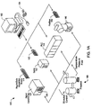
- the industrial automation system 140 is similar to the instrumentation or test and measurement system 100 shown in Figure 1. Elements which are similar or identical to elements in Figure 1 have the same reference numerals for convenience.
- the system 140 comprises a computer 102 which connects to one or more devices or instruments.
- the computer 102 comprises a CPU, a display screen, memory, and one or more input devices such as a mouse or keyboard as shown.
- the computer 102 connects through the one or more devices to a process or device 160 to perform an automation function, such as MMI (Man Machine Interface), SCADA (Supervisory Control and Data Acquisition), portable or distributed acquisition, advanced analysis, or control.
- MMI Man Machine Interface
- SCADA Supervisory Control and Data Acquisition
- the one or more devices may include a data acquisition board 114, a serial instrument 142, a PLC (Programmable Logic Controller) 144, or a fieldbus network card 156.
- the data acquisition board 114 is coupled to or comprised in the computer 102, and preferably interfaces through signal conditioning circuitry 124 to the process 160.
- the signal conditioning circuitry 124 preferably comprises an SCXI (Signal Conditioning extensions for Instrumentation) chassis comprising one or more SCXI modules 126.
- the serial instrument 142 is coupled to the computer 102 through a serial interface card 152, or through a serial port, such as an RS-232 port, provided by the computer 102.
- the PLC 144 couples to the computer 102 through a serial port, Ethernet port, or a proprietary interface.
- the fieldbus interface card 156 is preferably comprised in the computer 102 and interfaces through a fieldbus network to one or more fieldbus devices, such as valve 146.
- Each of the DAQ card 114, the serial card 152 and the fieldbus card 156 are typically plugged in to an I/O slot in the computer 102 as described above. However, these cards 114, 12 and 156 are shown external to computer 102 for illustrative purposes. In typical industrial automation systems a device will not be present of each interface type, and in fact many systems may only have one or more devices of a single interface type, such as only PLCs. The devices are coupled to the device or process 160.
- one or more of the devices connected to the computer 102 include programmable hardware according to the present invention.
- the data acquisition board 114, the serial instrument 142, the serial interface card 152, the PLC 144, or the fieldbus network card 156 include programmable hardware according to the present invention
- the programmable hardware comprises an FPGA (field programmable gate array).
- the computer 102 preferably includes a memory media, such as a non-volatile media, e.g., a magnetic media, CD-ROM, or floppy disks 104, or a volatile media, such as computer system memory, e.g., random access memory (RAM).
- the memory media preferably stores a graphical programming development system for developing graphical programs.
- the memory media also stores computer programs according to the present invention which are executable to convert at least a portion of a graphical program into a form for configuring or programming the programmable hardware or FPGA.
- the preferred embodiment includes a software program stored on a memory and/or hard drive of the computer 102 and executed by a CPU of the computer 102.
- the CPU executing code and data from the memory thus comprises a means for converting graphical code into a hardware implementation according to the steps described below.
- the instruments or devices in Figures 1 and 1A are controlled by graphical software programs, optionally a portion of which execute on the CPU of the computer 102, and at least a portion of which are downloaded to the programmable hardware for hardware execution.
- the graphical software programs which perform data acquisition, analysis and/or presentation, e.g., for instrumentation control or industrial automation, are referred to as virtual instruments.
- LabVIEW is comprised in the LabVIEW or BridgeVIEW graphical programming systems, hereafter collectively referred to as LabVIEW, available from National Instruments.
- LabVIEW is intended to include graphical programming systems which include G programming functionality, i.e., which include at least a portion of LabVIEW graphical programming functionality, including the BridgeVIEW graphical programming system.
- graphical programming system is intended to include any of various types of systems which are used to develop or create graphical code or graphical programs, including LabVIEW and BridgeVIEW from National Instruments, Visual Designer from Intelligent Instrumentation, Hewlett-Packard's VEE (Visual Engineering Environment), Snap-Master by HEM Data Corporation, DASYLab by DasyTec, GFS DiaDem, and ObjectBench by SES (Scientific and Engineering Software), among others.
- the graphical programs and programmable hardware are involved with data acquisition/generation, analysis, and/or display, and for controlling or modeling instrumentation or industrial automation hardware
- the present invention can be used to create hardware implementations of graphical programs for a plethora of applications and are not limited to instrumentation or industrial automation applications.
- Figures 1 and 1A are exemplary only, and the preferred embodiments may be used in any of various types of systems.
- the system and method of the preferred embodiments are operable for automatically creating hardware implementations of graphical programs or graphical code for any of various types of applications, including general purpose software applications such as word processing, spreadsheets, network control, games, etc.
- the computer 102 includes at least one central processing unit or CPU 160 which is coupled to a processor or host bus 162.
- the CPU 160 may be any of various types, including an x86 processor, a PowerPC processor, a CPU from the Motorola family of processors, a CPU from the SPARC family of RISC processors, as well as others.
- Main memory 166 is coupled to the host bus 162 by means of memory controller 164.
- the main memory 166 stores a graphical programming system, and also stores software for converting at least a portion of a graphical program into a hardware implementation. This software will be discussed in more detail below.
- the main memory 166 also stores operating system software as well as the software for operation of the computer system, as well known to those skilled in the art.
- the host bus 162 is coupled to an expansion or input/output bus 170 by means of a bus controller 168 or bus bridge logic.
- the expansion bus 170 is preferably the PCI (Peripheral Component Interconnect) expansion bus, although other bus types can be used.
- the expansion bus 170 includes slots for various devices such as the data acquisition board 114 (of Figure 1), a GPIB interface card 122 which provides a GPIB bus interface to the GPIB instrument 112 (of Figure 1), and a VXI or MXI bus card 230 coupled to the VXI chassis 116 for receiving VXI instruments.
- the computer 102 further comprises a video display subsystem 180 and hard drive 182 coupled to the expansion bus 170.
- One or more of the interface cards or devices coupled to the expansion bus such as the DAQ card 114, the GPIB interface card 122, the GPIB instrument 112, or the VXI or MXI bus card 230 comprises an embedded system comprising an embedded CPU and embedded memory.
- FIG. 3 a block diagram illustrating an interface card configured with programmable hardware according to the present invention is shown. It is noted that Figure 3 is exemplary only, and an interface card or device configured with programmable hardware according to the preferred embodiment may have various architectures or forms, as desired.
- the interface card illustrated in Figure 3 is the DAQ interface card 114 shown in either of Figures I or 1A.
- the programmable hardware may be included on any of the various devices shown in Figures 1 or 1A, or on other devices, as desired.
- the interface card 114 includes an I/O connector 202 which is coupled for receiving signals.
- the I/O connector 202 presents analog and/or digital connections for receiving/providing analog or digital signals.
- the I/O connector 202 is adapted for coupling to SCXI conditioning logic 124 and 126, or is adapted to be coupled directly to a unit under test 130 or process 160.
- the interface card 114 also includes data acquisition (DAQ) logic 204.
- DAQ data acquisition
- the data acquisition logic 204 comprises analog to digital (A/D) converters, digital to analog (D/A) converters, timer counters (TC) and signal conditioning (SC) logic as shown.
- the DAQ logic 204 provides the data acquisition functionality of the DAQ card 114.
- the interface card 114 includes a programmable hardware element or programmable processor 206.
- the programmable hardware 206 comprises a-field programmable gate array (FPGA) such as those available from Xilinx, Altera, etc.
- the programmable hardware element 206 is coupled to the DAQ logic 204 and is also coupled to the local bus interface 208.
- a graphical program can be created on the computer 102, or on another computer in a networked system, and at least a portion of the graphical program can be converted into a hardware implementation form for execution in the FPGA 206.
- the portion of the graphical program converted into a hardware implementation form is preferably a portion which requires fast and/or real-time execution
- the interface card 114 further includes a dedicated on-board microprocessor 212 and memory 214. This enables a portion of the graphical program to be compiled into machine language for storage in the memory 214 and execution by the microprocessor 212. This is in addition to a portion of the graphical program being converted into a hardware implementation form in the FPGA 206. Thus, in one embodiment, after a graphical program has been created, a portion of the graphical program is compiled for execution on the embedded CPU 212 and executes locally on the interface card 114 via the CPU 212 and memory 214, and a second portion of the graphical program is translated or converted into a hardware executable format and downloaded to the FPGA 206 for hardware implementation.
- the interface card 114 further includes bus interface logic 216 and a control/data bus 218.
- the interface card 114 is a PCI bus-compliant interface card adapted for coupling to the PCI bus of the host computer 102, or adapted for coupling to a PXI (PCI extensions for Instrumentation) bus.
- the bus interface logic 216 and the control/data bus 218 thus present a PCI or PXI interface.
- the interface card 114 also includes local bus interface logic 208.
- the local bus interface logic 208 presents a RTSI (Real Time System Integration) bus for routing timing and trigger signals between the interface card 114 and one or more other devices or cards.
- RTSI Real Time System Integration
- the interface card 114 also includes a non-volatile memory 215 coupled to the programmable hardware element 206.
- the non-volatile memory is operable to store the hardware description received from the host computer system to enable execution of the hardware description in the programmable hardware element 206 prior to or during booting of the computer system 102.
- the CPU 212 and memory 214 are not included on the interface card 114, and thus only the portion of the graphical program which is converted into hardware implementation form is downloaded to the FPGA 206.
- any supervisory control portion of the graphical program which is necessary or desired to execute in machine language on a programmable CPU is executed by the host CPU in the computer system 102, and is not executed locally by a CPU on the interface card 114.
- the CPU 212 is not included on the interface card 114, i.e., the interface card 114 includes the FPGA 206 and the memory 214.
- the memory 214 is used for storing FPGA state information.
- Figure 3B is the currently preferred embodiment.
- the preferred embodiment comprises a computer-implemented method for generating hardware implementations of graphical programs or graphical code. It is noted that various of the steps in the flowcharts below can occur concurrently or in different orders.
- the method below presumes that a graphical programming development system is stored in the memory of the computer system for creation of graphical programs.
- the graphical programming system is the LabVIEW graphical programming system available from National Instruments.
- the user creates the graphical program in a graphical program panel, referred to as a block diagram window and also creates a user interface in a graphical front panel.
- the graphical program is sometimes referred to as a virtual instrument (VI).
- VI virtual instrument
- the graphical program or VI will typically have a hierarchy of sub-graphical programs or sub-VIs.
- the user first creates a graphical program, also sometimes referred to as a block diagram.
- the graphical program comprises a graphical data flow diagram which specifies functionality of the program to be performed.
- This graphical data flow diagram is preferably directly compilable into machine language code for execution on a computer system.
- step 304 the method operates to export at least a portion of the graphical program to a hardware description.
- the hardware description is preferably a VHDL description, e.g., a VHDL source file, or alternatively is a high level net list description.
- the hardware description comprises a high level hardware description of function blocks, logic, inputs, and outputs which perform the operation indicated by the graphical program. The operation of exporting at least a portion of a the graphical program to a hardware description is discussed in more detail with the flowchart of Figure 6.
- the user specifies portions, e.g. sub VIs, which are to be exported to the hardware description format for conversion into hardware implementation.
- portions e.g. sub VIs
- the user selects the option to export a portion of the graphical program to the hardware description format, the user selects which modules or sub-VIs at that time which are to be exported to the hardware description.
- step 306 the method operates to convert the hardware description into an FPGA-specific net list.
- the net list describes the components required to be present in the hardware as well as their interconnections. Conversion of the hardware description into the FPGA-specific net list is preferably performed by any of various types of commercially available synthesis tools, such as those available from Xilinx, Altera, etc.
- the converting step 306 may utilize one or more pre-compiled function blocks from a library of pre-compiled function blocks 308.
- the hardware description created in step 304 includes a reference to a pre-compiled function block from the library 308.
- the hardware implementations for all of the function blocks are included in the function library.
- the respective pre-compiled function blocks are simply inserted into the net list in place of these references in step 306.
- the preferred embodiment thus includes the library 308 of pre-compiled function blocks, also refereed to as the component library, which are used in creating the net list.
- the preferred embodiment also includes hardware target specific information 310 which is used by step 306 in converting the hardware description into a net list which is specific to a certain type or class of FPGA.
- step 312 the method operates to compile the net list into an FPGA program file, also referred to as a software bit stream.
- the FPGA program file is a file that can be readily downloaded to program an FPGA.
- step 314 the method operates to transfer the FPGA program file to the programmable hardware, e.g., the FPGA, to produce a programmed hardware equivalent to the graphical program.
- the portion of a graphical program referenced in step 304 is comprised as a hardware implementation in an FPGA or other programmable hardware element.
- steps 306 and 312 can be combined into a single step, as can steps 304 and 306.
- steps 304 and 314 can be automatically performed.
- Figure 4A is a more detailed flowchart diagram illustrating operation of the preferred embodiment of the invention, including compiling a first portion of the graphical program into machine language and converting a second portion of the graphical program into a hardware implementation.
- the user can optionally select a first portion to be compiled into machine code for CPU execution as is normally done.
- the user preferably selects a supervisory control and display portion of the graphical program to be compiled into machine code for a CPU execution.
- the first portion comprising supervisory control and display portions is compiled for execution on a CPU, such as the host CPU in the computer 102 or the CPU 212 comprised on the interface card 114. This enables the supervisory control and display portions to execute on the host CPU, which is optimal for these elements of the program.
- the user selects a second portion for conversion to hardware implementation, which is performed as described above in steps 304-314 of Figure 4.
- the portion of the graphical program which is desired for hardware implementation preferably comprises modules or VIs which require a fast or deterministic implementation and/or are desired to execute in a stand-alone hardware unit.
- portions of the graphical program which are desired to have a faster or more deterministic execution are converted into the hardware implementation.
- the entire graphical program is selected for conversion to a hardware implementation, and thus step 322 is not performed.
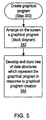
- FIG. 5 is a more detailed flowchart diagram of step 302 of Figures 4 and 4A, illustrating creation of a graphical program according to the preferred embodiment of the invention.
- the user arranges on the screen a graphical program or block diagram. This includes the user placing and connecting, e.g., wiring, various icons or nodes on the display screen in order to configure a graphical program. More specifically, the user selects various function icons or other icons and places or drops the icons in a block diagram panel, and then connects or "wires up" the icons to assemble the graphical program.
- the user also preferably assembles a user interface, referred to as a front panel, comprising controls and indicators which indicate or represent input/output to/from the graphical program.
- a front panel comprising controls and indicators which indicate or represent input/output to/from the graphical program.
- the method operates to develop and store a tree of data structures which represent the graphical program.
- the graphical programming system operates to develop and store a tree of data structures which represent the graphical program. More specifically, as the user assembles each individual node and wire, the graphical programming system operates to develop and store a corresponding data structure in the tree of data structures which represents the individual portion of the graphical program that was assembled.
- steps 342 and 344 are an iterative process which are repetitively performed as the user creates the graphical program.
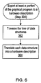
- FIG 6 is a flowchart diagram of step 304 of Figures 4 and 4A, illustrating operation when the method exports a portion of the graphical prcgram into a hardware description.
- the tree of data structures created and stored in step 344 preferably comprises a hierarchical tree of data structures based on the hierarchy and connectivity of the graphical program.
- the method traverses the tree of data structures and in step 364 the method operates to translate each data structure into a hardware description format.
- the method first flattens the tree of data structures prior to traversing the tree in step 362.
- a number of different function icons and/or primitives can be placed in a diagram or graphical program for conversion into a hardware implementation.
- These primitives include, but are not limited to, function nodes, constants, global variables, control and indicator terminals, structure nodes, and sub-VIs, etc.
- Function icons or primitives can be any data type, but in the current embodiment are limited to Integer or Boolean data types.
- global variables are preferably comprised on a single global panel for convenience. If a VI appears multiple times, then the VI is preferably re-entrant and may have state information. If a VI is not re-entrant, then preferably multiple copies of the VI are created in hardware if the VI has no state information, otherwise it would be an error.
- each node which is converted to a hardware description includes an Enable input, a Clear_Enable signal input, a master clock signal input and an Enable_Out or Done signal.
- the Enable input guarantees that the node executes at the proper time, i.e., when all of its inputs have been received.
- the Clear_Enable signal input is used to reset the node if state information remembers that the node was done.
- the Enable_Out or Done signal is generated when the node completes and is used to enable operation of subsequent nodes which receive an output from the node.
- Each node which is converted to a hardware description also includes the data paths depicted in the graphical program.
- control block includes a diagram enable out for each sub-diagram and a diagram done input for each sub-diagram.
- all global variables have numerous additional signals, including CPU interface signals which are specific to the type of CPU and bus, but typically include data lines, address lines, clock, reset and device select signals. All VIs and sub-VIs also include CPU interface signals if they contain a global variable.
- a string control is preferably placed on the front panel iabeled VHDL.
- the default text of the string control is placed in the text file created for the VHDL of the VI.
- a library of VIs are provided each representing a physical component or resource available in or to the FPGA. As these VHDL files representing these VIs are used, the method of the present invention monitors their usage to ensure that each hardware resource is used only once in the hierarchy of VIs being exported to the FPGA. When the VHDL file is written, the contents of the string control are used to define the access method of that hardware resource.
- the method starts at the VI level (the top level) and begins generation of VHDL by sending a message to the top level diagram.
- the method in turn effectively provides a message from the diagram to each constant, each node, and each signal in the diagram.
- the method then declares the signal type.
- the method declares a type of the component needed, and also declare an AND-gate with the proper number of inputs needed in order to enable itself.
- basic nodes declare an AND-gate with a number of inputs corresponding to the number of inputs received by the node.
- optimization is preferably performed to minimize the number of inputs actually needed. For example, if a node has three inputs, the node does not necessarily need a three input AND-gate if two of those inputs are coming from a single node. As another example, if one input comes from node A and another input comes from node B, but node A also feeds node B, then the input from node A is not needed in the AND gate. Thus various types of optimization are performed to reduce the number of inputs to each AND gate.
- the method also lists the connections for all of its inputs as well as the connections for all inputs to the enabling AND-gate.
- the method simply declares the type and the value of the constant.
- the method declares a While loop controller component.
- the method also declares an AND-gate, lists AND-gate inputs, and lists node inputs in a similar manner to the basic node described above.
- the method then declares the type for each shift register and includes a component for the shift register, and lists all the connections for the shift register inputs. If any tunnels are present on the While loop, the method declares the type of each tunnel component and list the connections for the inputs to the tunnels. For most tunnels, the method simply equivalences the signals for the inside and outside, without any effect.
- the method proceeds in a similar manner for Case and Sequence structures.
- Case and Sequence structures the method declares a case select controller component or a sequence controller component, respectively.
- the method also declares an AND-gate, lists AND-gate inputs, and lists node inputs in a similar manner to the basic node described above. The method then declares the component needed for any tunnels and list the connections for the inputs to the tunnels.
- the method sends a message to the sub-VI and associates inputs and outputs of the sub-VI with those of n.
- the method then declares an AND-gate, lists AND-gate inputs, and lists node inputs in a similar manner to the basic node described above.
- Figure 7 is a flowchart diagram illustrating operation when the method exports an input terminal into the hardware description format.
- the method determines if the data provided to the input terminal is input from a portion of the graphical program which will be executing on the CPU, i.e., the portion of the graphical program which is to be compiled into machine language for execution on the CPU, or whether the data is input from another portion of the graphical program that is also being transformed into a hardware implementation.
- step 406 the method creates a hardware description of a write register with a data input and data and control outputs.
- the write register is operable to receive data transferred by the host computer, i.e., generated by the compiled portion executing on the CPU.
- step 408 the data output of the write register is connected for providing data output to other elements in the graphical program portion.
- the control output of the write register is connected to other elements in the graphical program portion for controlling sequencing of execution, in order to enable the hardware description to have the same or similar execution order as the graphical program.
- step 404 the method ties the data output from the prior node into this portion of the hardware description, e.g., ties the data output from the prior node into the input of dependent sub-modules as well as control path logic to maintain the semantics of the original graphical program.
- Figure 8 is a flowchart diagram illustrating operation where the method exports a function node into the hardware description format.
- the term "function node” refers to any various types of icons or items which represent a function being performed.
- a function node icon represents a function being performed in the graphical program.
- Examples of function nodes include arithmetic function nodes, e.g., add, subtract, multiply, and divide nodes, trigonometric and logarithmic function nodes, comparison function nodes, conversion function nodes, string function nodes, array and cluster function nodes, file I/O function nodes, etc.
- step 422 the method determines the inputs and outputs of the function node.
- step 424 the method creates a hardware description of the function block corresponding to the function node with the proper number of inputs and outputs as determined in step 422.
- the method includes a reference in the hardware description to a pre-compiled function block from the library 308. In this case, the method also includes the determined number of inputs and outputs of the function node.
- step 426 the method traverses the input dependencies of the node to determine which other nodes provide outputs that are provided as inputs to the function node being converted.
- step 428 the method creates a hardware description of an N input AND gate, wherein N is the number of inputs to the node, with each of the N inputs connected to control outputs of nodes which provide inputs to the function node.
- the output of the AND gate is connected to a control input of the function block corresponding to the function node.
- a function node can only execute when all of its inputs have been received.
- the AND gate created in step 428 emulates this function by receiving all control outputs of nodes which provide inputs to the function node.
- the AND gate operates to effectively receive all of the dependent inputs that are connected to the function node and AND them together to provide an output control signal which is determinative of whether the function node has received all of its inputs.
- the output of the AND gate is connected to the control input of the function block and operates to control execution of the function block.
- the function block does not execute until the AND gate output provided to the control input of the function block provides a logic signal indicating that all dependent inputs which are input to the function node have been received.
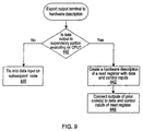
- Figure 9 is a flowchart diagram illustrating operation where the method exports an output terminal into the hardware description.
- the method determines if the data provided from the output terminal is output to a portion of the graphical program which will be executing on the CPU, i.e., the portion of the graphical program which is to be compiled into machine language for execution on the CPU, or whether the data is output to another portion of the graphical program that is also being transformed into a hardware implementation.
- step 442 the method creates a hardware description of a read register with a data input and data and control outputs.
- the read register is operable to receive data generated by logic representing a prior node in the graphical program.
- step 444 the method connects the data output of a prior node to the data input of the read register.
- control input of the read register is also connected to control sequencing of execution, i.e., to guarantee that the read register receives data at the proper time. This enables the hardware description to have the same or similar execution order as the graphical program.
- step 446 the method ties the data output from the output terminal into a subsequent node in this portion ofthe hardware description, e.g., ties the data output from the output terminal into the input of subsequent sub-modules as well as control path logic to maintain the semantics of the original graphical program.
- Figure 10 is a flowchart diagram illustrating operation where the method exports a structure node into the hardware description.
- structure node refers to a node which represents control flow of data, including iteration, looping, sequencing, and conditional branching. Examples of structure nodes include For/Next loops, While/Do loops, Case or Conditional structures, and Sequence structures. For more information on structure nodes, please see the above LabVIEW patents referenced above.
- the flowchart of Figure 10 illustrates exporting a loop structure node into a hardware description.
- the method examines the structure node parameters, e.g., the iteration number, loop condition, period, phase delay, etc.
- the graphical programming system preferably allows the user to insert certain parameters into a structure node to facilitate exporting the structure node into a hardware description.
- Iteration and looping structure nodes have previously included an iteration number and loop condition, respectively.
- these structure nodes further include period and phase delay parameters, which are inserted into or assigned to the structure node. These provide information on the period of execution and the phase delay of the structure node.
- the period and phase delay parameters, as well as the iteration number or loop condition are used to facilitate exporting the structure node into a hardware description.
- step 464 the method inserts the structure node parameters into the hardware description.
- step 466 the method inserts a reference to a pre-compiled function block corresponding to the type of structure node.
- the method inserts a reference to a pre-compiled function block which implements the looping function indicated by the structure node. The method also connects controls to the diagram enclosed by the structure node.
- Figure 11 is a flowchart diagram or a portion of step 306 of Figures 4 and 4A, illustrating operation where the method converts the hardware description for a node into a net list.
- Figure 11 illustrates operation of converting a hardware description of a node, wherein the hardware description comprises a reference to a function block and may include node parameters. It is noted that where the hardware description of a node comprises a description of the actual registers, gates, etc. which perform the operation of the node, then conversion of this hardware description to a net list is readily performed using any of various types of synthesis tools.
- step 502 the method examines the function block reference and any node parameters present in the hardware description.
- step 504 the method selects the referenced pre-compiled function block from the library 308, which essentially comprises a net list describing the function block.
- step 506 the method then configures the pre-compiled function block net list with any parameters determined in step 502.
- step 508 the method then inserts the configured pre-compiled function block into the net list which is being assembled.
- Figure 12 is a flowchart diagram illustrating operation of the flowchart of Figure 11, where the method converts the hardware description for a structure node into a net list.
- Figure 12 illustrates operation of converting a hardware description of a structure node, wherein the hardware description comprises a reference to a structure node function block and includes structure node parameters.
- the method examines the function block reference and the structure node parameters present in the hardware description.
- the structure node parameters may include parameters such as the iteration number, loop condition, period, phase delay, etc.
- the method selects the referenced pre-compiled function block from the library 308, which essentially is a net list describing the structure node function block.
- the method then configures the pre-compiled function block net list with the structure node parameters determined in step 502A. This involves setting the period and phase delay of execution of the structure node as well as any other parameters such as iteration number, loop condition, etc.
- the method then inserts the configured pre-compiled function block into the net list which is being assembled.
- Figure 13 is a block diagram illustrating a While loop function block.
- the While loop function block includes enabling period and phase inputs as well as a loop control input.
- the While loop function block provides an index output which is provided to and adder.
- the adder operates to increment each time the index signals provided to monitor the number of times the While loop is executed.
- the While loop further outputs Clear and Enable Out signals to control the program within the While loop and further receives a Loop Done signal input which is used to indicate whether the loop has completed.
- Figure 14 is a state diagram illustrating operation of the while loop function block shown in Figure 13. As shown, a diagram start operation precedes to state A. When Phase Done is true indicating that the phase has completed, then the state machine advances to state B. The state machine remains in state B until the Loop Enable signal is true, indicating that the loop has been enabled to begin execution. When the Loop Enable signal is asserted, the state machine advances from state B to state C. In state C the Clear Output signal is asserted, clearing the loop output prior to execution of the loop.
- the state machine then advances from state C to state D.
- state D the computation is performed, and the Set Enable out signal is asserted. If the period is done and the loop is not yet completed, signified by the equation: Period Done and /Loop Done then the state machine proceeds to an error state and operation completes.
- the period set for execution for the loop was not sufficiently long to allow the loop to complete. In other words, the loop took more time to complete than the period set for execution of the loop.
- the state machine advances from state D to state E when the Loop Done signal is asserted prior to the Period Done signal being asserted, indicating that the loop has completed prior to the period allotted for the loop execution being over.
- the state machine then advances from state E to a wait state, as shown. If the period is done and the loop is not re-mabled, signified by the condition: Period Done & /Loop Enabled then the state machine advances from the Wait to the Done state. If the period has completed and the loop is still enabled, indicating that another execution of the loop is necessary, then the state machine advances from the Wait state back to the C state. Thus, the state machine advances through state C, D, E, and Wait to perform looping operations.
- the host CPU merely downloads the configuration to the programmable logic as described above. This could occur by the driver at boot up time or when the user presses the run button on the graphical program that was created.
- the host CPU provides the hardware implementation to a non-volatile memory comprised on the board, and during boot up of the board this hardware implementation is loaded from the non-volatile memory on the board into the programmable logic.
- the reconfigurable board can be designed so that the hardware diagram is written to non-volatile memory instead of directly to the FPGA.
- the diagram preferably has top-level cnable_in and abort signals which can be configured at compile time to either allow immediate execution or to require a supervisory program to enable hardware execution.
- the system comprises a computer system which includes an add-in card.
- the add-in card preferably performs a data acquisition/generation function, e.g., is a data acquisition card.
- the DAQ card includes D/A and A/D converters as well as various other data acquisition logic, and includes a programmable logic device such as an FPGA which is operable to receive a hardware implementation created in response to a graphical program created on the computer system.
- the programmable logic or FPGA is operable to receive a default configuration, whereby the default configuration operates to configure the data acquisition board with a standard interface for execution of the graphical program in software.
- the host CPU may download a hardware implementation to the FPGA which programs the FPGA with a default configuration of a board to provide a desired interface for the board.
- This configuration would provide the host computer with direct access to the I/O of the board. This is useful, for example in hardware simulation, to allow the host CPU to execute the graphical program or diagram in software during algorithm development to determine feasibility and perform debugging etc.
- the graphical program behaves the same as it normally would in hardware, except the program runs slower due to software execution.
- the host CPU merely downloads the configuration to the progammable logic as described above. This could occur by the driver at boot up time or when the user presses the run button on the graphical program that was created.
- the host CPU provides the default configuration to a non-volatile memory comprised on the board, and during boot up of the board this default configuration is loaded from the non-volatile memory on the board into the programmable logic.
- the graphical programming system includes a data structure which includes a listing of each of the elements or components comprised in the component library, as well as the corresponding cost of each component in terms of gates and time of execution.
- the graphical programming system operates to reference the data structure to obtain the associated gate and time costs associated with each component being used from the component library in the graphical program being constructed. For example, the graphical programming system totals the amount of gates utilized with regard to each component being used in the graphical program being constructed, and then determines if the programmable logic or FPGA being used has sufficient capacity to implement that graphical program.
- the graphical programming system can use this data structure to determine at or prior to compile time how fast the graphical program will execute in hardware, i.e., how fast the hardware implementation will execute in the FPGA.
- the graphical programming system receives user input regarding desired execution time and utilizes the execution times of each of the elements to provide feedback to the user as to whether the graphical program satisfies the users requirements regarding time of execution.
- the component library includes multiple versions of respective components.
- the component library includes a fast multiplier that is large and a small multiplier that is slow.
- the graphical programming system can be configured to select the appropriate version of component based on how much of the FPGA is consumed by the rest of the diagram and based on the loop times indicated in the diagram, or other input from the user and/or information in the diagram.
- the user inputs both the number of gates comprised in the programmable logic being used as well as the desired time of execution, and the graphical programming system automatically selects among various versions of components in the component library, e.g., a slower and less complex adder vs. a faster but more complex adder, in order to develop a hardware implementation which is suitable for the user's application.
- the hardware device or board When a user creates a graphical program which manipulates one or more hardware resources, such as one or more hardware resources comprised on an add-in board, e.g., a data acquisition board, in general the hardware device or board will have a limited number of hardware elements that are useable by the graphical program. For example, a given data acquisition board may only have one analog input channel. At least a subset of these hardware elements may only be used once, i.e., are not re-useable.
- the non-reusable components comprised on the hardware being controlled appear on a palette during configuration or construction of the graphical program. These non-reusable components disappear as they are used by the diagram to indicate to the user that these components have been used and thus cannot be reused.
- the user simply drags these non-reusable components from the palette into the graphical program. Once these components are dragged from the palette into the graphical program, the component disappears from the palette, and thus the user knows that the component has been used in the graphical program and is thus not available for reuse.
- a corresponding two or more components appear in the palette.
- the corresponding picture in the palette disappears to alert the user as to the number of remaining hardware components which can be used. This provides a convenient mechanism for providing information to the user regarding the hardware components used and prevents reuse of a non-reusable component.
- a single graphical program it is often convenient for a single graphical program to access a single hardware element from several locations in the graphical program or diagram. This would technically violate the single instance or non re-useability concept discussed above, whereby a non-reusable component can be used only once in a graphical program.
- the user preferably constructs sequencing or implements sequencing in the graphical program which prevents this hardware element from being used simultaneously within the same graphical program. For example, in the LabVIEW program the user constructs sequencing using a sequence structure.
- references to hardware elements in the graphical program provide a "handle" to the hardware which is provided to the graphical program which can be used in multiple locations within the graphical program. This reference or "handle" to the hardware can then be used to provide simultaneous accesses to a single device in the graphical program.
- a graphical program or diagram can be constructed to access unique hardware resources.
- a single reference to the hardware appears in the diagram as discussed above.
- multiple references to the hardware appear in the graphical program, but no two of these references occur simultaneously. For example, the user can figure these multiple references in different frames of a sequence structure.
- the graphical program includes multiple references to the hardware, and the way in which the graphical program is constructed indicates that these multiple references may be executed simultaneously.
- the graphical programming system preferably detects which of the above cases exist and performs any necessary type of configuration to accommodate these situations.
- case (a) a single reference to the hardware appears in the graphical program, and thus the graphical programming system is not required to perform any special processing in generating the hardware implementation.
- the graphical program when converting the sequence structure to a hardware implementation, utilizes multiplexers to multiplex the control and data inputs to the hardware in question with the same signals to guarantee that simultaneous accesses are impossible, as indicated by the sequence structure.
- the graphical programming system preferably automatically detects an instance where multiple references in the hardware appear, wherein they may be executed simultaneously, and configures the hardware implementation to prevent these multiple accesses, and thus thereby preventing possible erroneous operation.
- the graphical programming system during the conversion process to the hardware implementation, detects the multiple references to the hardware which can be executed simultaneously, and instantiates one or more multiplexers and a full arbitration circuit to control the multiplexers.
- the multiplexers are provided in the hardware implementation to prevent or avoid the possibility of simultaneous execution of these multiple references to the non-reusable hardware.
- cases (b) and (c) use similar multiplexers.
- the difference between cases (b) and (c) is that in case (c) the hardware implementation includes a control circuit.
- the control signals are the same control signals that control which frame of the sequence is executing, and in (c) the control signals come from an arbitration circuit.
- the multiplexers that configure and implement the sequence structure are set or defined at compile time.
- the arbitration unit is not necessarily defined as far as ordering at compile time, but the order of execution is actually defined at run time.
- a user may insert one or more probes into the graphical program which operate to display data on the respective wire where the probe is located during execution of the graphical program.
- the corresponding hardware implementation directs the use of a time stamp generation circuit.
- the time stamp generation circuit may be included inside the programmable logic or FPGA, or the time stamp generation circuit is configured in a separate chip or logic block included on the board which is coupled to the FPGA.
- This time stamp generation circuit allows the graphical programming system to insert probes into the hardware implementation of the graphical program or diagram.
- the time stamp generation circuit thus comprises a hardware implementation of the probe which was inserted in the software graphical program. This enable the hardware debugging environment to look and feel the same as it does in the graphical programming system.
- the graphical programming system is operable to detect graphical programs or diagrams that are streaming data to/from the host computer, and the graphical programming system inserts special circuits in the hardware implementation to handle DMA for high speed transfers without special consideration from the user. These circuits include FIFOs and circuits to generate DMA requests (DRQ) or the equivalent.
- This method enables the graphical programming system to automatically generate a DMA circuit for the graphical program or diagram created by the user.
- all communication to the graphical program or diagram from the CPU passes through global variables.
- the diagram would include an icon which looks similar to a "write global" in the sense that it is a data sink and when the icon is executed, the icon would assert a DMA request (DRQ)that goes back to the DMA controller and triggers a DMA transfer.
- DRQ DMA request
- the FIFO and DRQ generation circuitry are built inside the FPGA when the DMA icon is used.
- the LabVIEW graphical programming system includes an occurrence capability which allows a first function to "go to sleep" while waiting for a second function to produce a result. In this manner, the first function does not consume any CPU time while waiting for the second function.
- Three icons are provided with associated control software which implement the occurrence function.
- a Wait on Occurrence function icon is associated with the first function that is waiting on the result from the second function.
- a Set Occurrence function icon is typically associated with the second function icon and triggers an occurrence when the second function produces the desired result.
- a Generate Occurrence function icon is used to pass identifier values linking multiple sources and destinations having Set Occurrence and Wait on Occurrence function icons, respectively.
- Occurrences share some of the properties of global variables in that their implementation depends greatly on whether they are "written” and “read” within a single environment (all in software, all in hardware, or crossing the software/hardware boundary).
- An occurrence that is set and detected within hardware involves set and detect occurrence components from the library.
- An occurrence that is set in hardware and detected by the host CPU can be mapped automatically to an interrupt.
- the graphical programming system e.g., LabVIEW, would then generate the interrupt handling code to run on the host computer.
- the hardware implementation generated by the graphical programming system can be configured to be controlled by other software environments or other protocols, e.g., C, C ++ , Java, Visual Basic, Visual C++, LabWindows CVI, other types of graphical programming systems, etc.
- the graphical programming system can automatically generate a description of the hardware necessary including a register map, interrupt map, DMA abilities, etc. to enable other software environments to control the hardware implementation.
- the graphical program constructed in LabVIEW is converted into a hardware implementation, wherein the hardware implementation also includes the above hardware information necessary to allow another software development environment to control or execute the hardware implementation.
- the embodiments preferably uses a third party tool which converts the net list created from the graphical program into a hardware implementation or FPGA configuration.
- this third party tool reports that the maximum clock speed is less than expected by the graphical programming system, then the graphical programming system can optionally reduce the clock speed and adjust one or more counter values and timers to compensate for this new clock speed. This is preferably performed in cases where overall performance goals are still met.
- the graphical programming system can automatically reduce the clock speed and adjust the counter values and respective timers to compensate for this new clock speed and thus provide the user with the expected performance that the user expected when he/she created the graphical program.
- This embodiment utilizes a configurable oscillator on the data acquisition board.
- Figure 15 illustrates a simple example of a graphical program.
- the graphical program includes three input terminals and one output terminal.
- the graphical program simply comprises a first 2-input Add function node which receives input from two inputs terminals, and a second 2-input Add function node which receives the output from the first Add function node and receives an output from the third input terminal.
- the second 2-input Add function node provides an output to output terminal as shown.
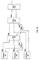
- Figure 16 is a conceptual diagram of the resulting hardware after the graphical program example of Figure 15 is converted into a hardware description.
- the hardware diagram includes three write registers 522 - 526 corresponding to each of the three input terminals.
- the data outputs of the first two write registers 522 and 524 are provided as inputs to a first two-input adder 532, which corresponds to the first adder in the block diagram of Figure 15.
- the hardware description also involves creating an AND gate 534 which receives control outputs from each of the first two write registers 522 and 524 and provides a single output to the control input of the adder 532.
- the purpose of the AND gate 534 is to prevent the adder 532 from executing until both inputs have been received.
- the Adder 532 provides a data output to a second two-input Adder 542, which corresponds to the second adder in the block diagram of Figure 15.
- the first Adder 532 also generates an enable out signal which is provided to an input of a second AND gate 536.
- the other input of the AND gate 536 receives an output from the third write register 526, corresponding to the third input terminal.
- the AND gate 536 provides an output to a control input of the second adder 542.
- the AND gate 536 operates to ensure that the second adder 542 does not execute until all inputs have been received by the adder 542.
- the second adder 542 provides a data output to a read register 546 associated with the output terminal.
- the second adder 542 also provides an enable out signal to the read register 546, which notifies the read register 546 when valid data has been provided.
- the flowchart diagram of Figure 6 is executed, which operates to create a hardware description of a write register 522, 524, and 526, each with data and control outputs.
- the flowchart diagram of Figure 7 is executed, which operates to create a hardware description of an adder 532 or 542, and further creates an associated N input AND gate 534 or 536, with inputs connected to the dependent inputs of the adder function node to ensure execution at the proper time.
- the flowchart diagram of Figure 8 Is executed for the output terminal of the graphical program, which operates to generate a hardware description of a read register with data and control inputs.
- Figures 17 - 19 Example of Converting a Graphical Program into a Hardware Implementation
- Figures 17 - 19 comprise a more detailed example illustrating operation of the preferred embodiments.
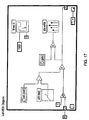
- Figure 17 illustrates an example graphical program (a LabVIEW diagram) which is converted into an FPGA implementation using the present invention.
- the graphical program comprises a plurality of interconnected nodes comprised in a While loop.
- the While loop includes shift register icons, represented by the down and up arrows at the left and right edges, respectively, of the While loop.
- a 0 constant positioned outside of the While loop is connected to the down arrow of the shift register at the left edge of the While loop.
- the While loop includes a timer icon representing or signifying timing for the While loop.
- the timer icon includes inputs for period and phase. As shown, the timer icon receives a constant of 1000 for the period and receives a constant of 0 for the phase.
- the While loop includes input terminals which are configured to receive timing information, such as period and phase.
- Figure 18 illustrates the IAbVIEW data structures created in response to or representing the diagram or graphical program of Figure 17.
- the data structure diagram of Figure 17 comprises a hierarchy of data structures corresponding to the diagram of Figure 17.
- the LabVIEW data structure representation includes a top level diagram which includes a single signal connecting the 0 constant to the left hand shift register of the While loop.
- the top level diagram includes only the constant (0) and the While loop.
- the While loop includes a sub-diagram which further includes left and right shift register terms, the continue flag of the While loop, a plurality of constants, a timer including period and phase inputs, global variables setpoint and gain, sub-VIs a/d read and d/a write, and various function icons, e.g., scale, add, subtract, and multiply. Further, each of the objects in the diagram have terminals, and signals connect between these terminals.
- Figure 19 illustrates a circuit diagram representing the hardware description which is created in response to the data structures of Figure 18.
- the circuit diagram of Figure 19 implements the graphical program of Figure 17.
- the CPU interface signals are bussed to the global variables.
- the CPU interface signals are also provided to the sub-VIs a/d read and d/a write.
- the While loop is essentially abstracted to a control circuit which receives the period and phase, and includes an external enable directing the top level diagram to execute, which starts the loop.
- the loop then provides a diagram enable(diag_enab) signal to start the loop and waits for a diagram done (diag_done) signal to signify completion of the loop, or the period to expire.
- the loop Based on the value of the Continue flag, the loop provides a subsequent diag_enab signal or determines that the loop has finished and provides a Done signal to the top level diagram.
- the loop control block also provides a diagram clear enable out (diag_clear_enab_out) signal to every node in the sub-diagram of the While loop.
- the loop control block outputs a diagram enable (diag_enab) signal that is fed to all of the starting nodes in the diagram within the While loop.
- the Done signals from these items are fed into an AND gate, whose output is provided to enable subsequent nodes.
- the shift register includes a data in, a data out and an enable input which clocks the data in (din) to the data out (dout), and a load which clocks the initial value into the shift register.
- VHDL description corresponding to the example of Figures 17 - 19, wherein the VHDL description was creased using the preferred embodiment:
- the preferred embodiment includes a component library that is used to aid in converting various primitives or nodes in a graphical program into a hardware description, such as a VHDL source file.
- a component library that is used to aid in converting various primitives or nodes in a graphical program into a hardware description, such as a VHDL source file.
- VHDL components in this component library, these being components for a While loop and a multiplier primitive.
- Whileloop.vhd shows how a While loop in a graphical program is mapped to a state machine in hardware. It is noted that other control structures such as a "For loop" are similar. Whileloop.vhd is as follows:
- prim_multiply_16.vhd VHDL component referred to as prim_multiply_16.vhd that the preferred embodiment uses when a multiplier primitive appears on a graphical program or diagram.
- a multiplier primitive appears on a graphical program or diagram.
- Prim_multiply_16.vhd is as follows:
- Figures 20 and 21 illustrate the graphical source code of a graphical program or VI called examplel.vi.
- VHDL hardware description created from the graphical program examplel.vi shown in Figures 20 and 21, wherein the VHDL hardware description set out below was directly generated from the LabVIEW program example1.vi using the preferred embodiment.
Landscapes
- Engineering & Computer Science (AREA)
- Theoretical Computer Science (AREA)
- General Engineering & Computer Science (AREA)
- Computer Hardware Design (AREA)
- Physics & Mathematics (AREA)
- General Physics & Mathematics (AREA)
- Software Systems (AREA)
- Quality & Reliability (AREA)
- Evolutionary Computation (AREA)
- Geometry (AREA)
- Stored Programmes (AREA)
- Programmable Controllers (AREA)
- Image Generation (AREA)
Claims (59)
- Procédé mis en oeuvre par ordinateur pour configurer un instrument pour réaliser une fonction de mesure, dans lequel l'instrument comporte un élément matériel programmable, le procédé comportant :la création d'un programme graphique, dans lequel le programme graphique met en oeuvre la fonction de mesure, dans lequel le programme graphique comporte une partie panneau avant et une partie schéma de principe, dans lequel la partie panneau avant fonctionne comme un panneau avant pour l'instrument ;la génération d'une description matérielle basée sur la partie schéma de principe du programme graphique, dans lequel la description matérielle décrit une mise en oeuvre matérielle de la partie schéma de principe du programme graphique ;la configuration de l'élément matériel programmable dans l'instrument utilisant la description matérielle pour produire un élément matériel configuré, dans lequel l'élément matériel configuré met en oeuvre une mise en oeuvre matérielle de la partie schéma de principe du programme graphique ;la compilation de la partie panneau avant en code exécutable pour exécution par un processeur et stockage de code exécutable dans une mémoire ;l'instrument acquérant un signal depuis une source externe après ladite configuration ;l'élément matériel programmable dans l'instrument réalisant la fonction de mesure sur le signal ; etle processeur réalisant le code exécutable depuis la mémoire pour présenter la partie panneau avant sur un écran pendant l'exécution par l'élément matériel programmable dans l'instrument de la fonction de mesure sur le signal.
- Procédé selon la revendication 1, le procédé comportant en outre :l'exécution d'une conversion analogique à numérique sur le signal après ladite acquisition et avant ladite exécution.
- Procédé selon la revendication 1, le procédé comportant en outre :la réception d'une entrée de la part de l'utilisateur par la partie panneau avant sur l'écran pour contrôler l'instrument pendant l'exécution par l'élément matériel programmable dans l'instrument de la fonction de mesure sur le signal.
- Procédé selon la revendication 3,
dans lequel la partie panneau avant comporte un ou plusieurs objets d'interface utilisateur ;
dans lequel ladite génération comporte l'incorporation d'un registre dans la description matérielle pour au moins un des objets d'interface utilisateur ;
dans lequel l'exécution de la fonction de mesure sur le signal par l'élément matériel programmable dans l'instrument comporte l'accès à un registre sur l'élément matériel programmable pour affecter un desdits objets d'interface utilisateur. - Procédé selon la revendication 1, dans lequel l'instrument comporte le processeur et la mémoire ;
dans lequel le processeur dans l'instrument exécute le code exécutable depuis la mémoire pour présenter la partie panneau avant sur l'écran pendant l'exécution par l'élément matériel programmable dans l'instrument de la fonction de mesure sur le signal. - Procédé selon la revendication 1, dans lequel l'instrument est couplé à un système informatique, dans lequel le système informatique comporte le processeur et la mémoire ;
dans lequel le système informatique exécute le code exécutable depuis la mémoire pour présenter le panneau avant sur l'écran pendant l'exécution par l'élément matériel programmable dans l'instrument de la fonction de mesure sur le signal. - Procédé selon la revendication 1, dans lequel l'instrument comporte en outre de la logique de temporisation/comptage, le procédé comportant en outre :la logique de temporisation/comptage réalisant une opération de temporisation/comptage pendant l'exécution de l'élément matériel programmable dans l'instrument de la fonction de mesure sur le signal.
- Procédé selon la revendication 1, dans lequel l'élément matériel programmable dans l'instrument exécute la réalisation d'une fonction de commande de processus utilisant le signal.
- Procédé selon la revendication 1, comportant en outre :dans lequel ladite configuration de l'élément matériel programmable comporte le téléchargement du fichier de programme matériel vers l'élément matériel programmable pour configurer l'élément matériel programmable.la conversion de la description matérielle en une liste des interconnections ; etla compilation du format de liste des interconnections en un fichier de programme matériel ;
- Procédé selon la revendication 9, dans lequel ladite conversion de la description matérielle en une liste des interconnections comporte :l'utilisation d'au moins un bloc de fonction d'une bibliothèque de blocs de fonction pré-compilés ; etl'utilisation d'informations spécifiques à une cible matérielle.
- Procédé selon la revendication 1, dans lequel ladite création du programme graphique comporte :dans lequel ladite génération de la description matérielle comporte :l'arrangement sur l'écran d'une pluralité de noeuds comportant le programme graphique ;la création et le stockage de structures de données qui représentent le programme graphique en réponse audit arrangement ;le balayage de la structure de données ;la conversion de la structure de données en un format de description matérielle en réponse audit balayage.
- Procédé selon la revendication 1, dans lequel le programme graphique comporte une pluralité de noeuds ;
dans lequel ladite génération de ladite description matérielle comporte la conversion de chacun desdits noeuds en un format de description matérielle. - Procédé selon la revendication 12, dans lequel chacun desdits noeuds est converti en un format de description matérielle comportant une entrée d'activation, une entrée de signal d'horloge et une sortie d'activation ;
dans lequel, pour un noeud respectif, ladite entrée d'activation reçoit un signal d'activation généré depuis des signaux de sortie d'activation d'un ou plusieurs noeuds qui fournissent des entrées au noeud respectif. - Procédé selon la revendication 12, dans lequel ledit programme graphique comporte un terminal d'entrée ;
dans lequel, pour ledit terminal d'entrée, ladite conversion comporte :l'action de déterminer si l'entrée de données au terminal d'entrée se fait depuis une partie interface utilisateur sur le système informatique ;la création d'une description matérielle d'un registre d'écriture, dans lequel le registre d'écriture comporte une ou plusieurs sorties de données et au moins une sortie de contrôle. - Procédé selon la revendication 12, dans lequel le programme graphique comporte un noeud de fonction ;
dans lequel, pour ledit noeud de fonction, ladite conversion comporte :la détermination des entrées et sorties vers/depuis le noeud de fonction ;la génération d'une description matérielle de logique qui exécute la fonction indiquée par le noeud de fonction ;le balayage des dépendances d'entrée du noeud ;la création d'une description matérielle sur la base d'une porte ET, comportant la liste des connexions desdites dépendances d'entrée du noeud à ladite porte ET. - Procédé selon la revendication 12, dans lequel le programme graphique comporte un noeud de structure ;
dans lequel, pour ledit noeud de structure, ladite conversion comporte :la détermination des entrées et sortie vers/depuis le noeud de structure ;la génération d'une description matérielle d'un bloc de contrôle qui exécute la fonction de contrôle indiquée par le noeud de structure ;le balayage des dépendances d'entrée du noeud ;la création d'une description matérielle d'une porte ET, comportant la liste des connexions desdites dépendances d'entrée du noeud à ladite porte ET. - Procédé selon la revendication 12, dans lequel ledit programme graphique comporte un terminal de sortie ;
dans lequel, pour ledit terminal de sortie, ladite conversion comporte :l'action de déterminer si la sortie de données depuis le terminal de sortie se fait vers une partie interface utilisateur sur le système informatique ;la création d'une description matérielle d'un registre de lecture, dans lequel le registre de lecture comporte une ou plusieurs entrée de données et au moins une entrée de contrôle. - Procédé selon la revendication 1, dans lequel le programme graphique comporte un organigramme de données.
- Procédé selon la revendication 1, dans lequel une première partie de la partie schéma de principe est convertie en une description matérielle ;
le procédé comportant en outre :la compilation d'une seconde partie de la partie schéma de principe en code machine pour exécution par le processeur. - Procédé selon la revendication 19, comportant en outre :dans lequel ladite exécution du code machine et l'élément matériel configuré réalisant la fonctionnalité fonctionnent pour réaliser la fonctionnalité indiquée par la partie schéma de principe du programme graphique.l'exécution du code machine pour réaliser la fonctionnalité indiquée par la seconde partie de la partie schéma de principe ;l'élément matériel configuré réalisant la fonctionnalité indiquée par la première partie de la partie schéma de principe ;
- Procédé selon la revendication 1, dans lequel l'instrument comporte une mémoire non volatile couplée à l'élément matériel programmable, le procédé comportant en outre ;
le stockage de la description matérielle dans la mémoire non volatile ;
dans lequel ladite configuration de l'élément matériel programmable comporte le transfert de la description matérielle de la mémoire non volatile vers l'élément matériel programmable pour produire l'élément matériel configuré. - Système de mesure, comportant :dans lequel la mémoire stocke un programme graphique, dans lequel le programme graphique met en oeuvre une fonction de mesure, dans lequel le programme graphique comporte une partie panneau avant et une partie schéma de principe, dans lequel la partie panneau avant fonctionne comme un panneau avant pour l'instrument ;un système informatique comportant une unité centrale, une mémoire et un écran ;
dans lequel ladite mémoire stocke également un logiciel qui est exécutable pour générer une description matérielle basée sur la partie schéma de principe du programme graphique, dans lequel la description matérielle décrit une mise en oeuvre matérielle de la partie schéma de principe du programme graphique ; et
un instrument couplé au système informatique, dans lequel l'instrument comporte :dans lequel le système informatique est utilisable pour compiler la partie panneau avant du programme graphique en code exécutable et stocker le code exécutable dans la mémoire ;une entrée pour acquérir un signal depuis une source externe ; etun élément matériel programmable, dans lequel l'élément matériel programmable dans l'instrument est configurable en utilisant la description matérielle pour produire un élément matériel configuré , dans lequel l'élément matériel configuré met en oeuvre une mise en oeuvre matérielle de la partie schéma de principe du programme graphique, dans lequel l'élément matériel programmable dans l'instrument est exécutable pour réaliser la fonction de mesure sur un signal acquis ;
dans lequel l'unité centrale dans le système informatique est utilisable pour réaliser le code exécutable pour présenter la partie panneau avant sur l'écran pendant que l'élément matériel programmable dans l'instrument s'exécute pour réaliser la fonction de mesure sur le signal. - Système de mesure selon la revendication 22, dans lequel l'instrument comporte en outre :une logique de conversion analogique à numérique couplée à l'entrée et à l'élément matériel programmable pour l'exécution de la logique de conversion analogique à numérique sur un signal analogique acquis pour produire un signal numérique.
- Système de mesure selon la revendication 22,
dans lequel la partie panneau avant est utilisable pour recevoir des entrées de la part d'un utilisateur afin de contrôler l'instrument pendant la fonction de mesure. - Système de mesure selon la revendication 22, dans lequel l'instrument comporte en outre une logique de temporisation/comptage ;
dans lequel la logique de temporisation/comptage exécute une opération de temporisation/comptage pendant l'exécution de la fonction de mesure sur le signal par l'élément matériel programmable dans l'instrument. - Procédé selon la revendication 22, dans lequel l'élément matériel programmable dans l'instrument exécute la réalisation d'une fonction de commande de processus utilisant le signal.
- Procédé selon la revendication 26, dans lequel le logiciel stocké dans la mémoire du système informatique est utilisable en outre pour convertir la description matérielle en une liste des interconnections ;
dans lequel le système informatique est utilisable pour configurer l'élément matériel programmable utilisant la liste des interconnections. - Système de mesure selon la revendication 22, dans lequel le logiciel stocké dans la mémoire du système informatique est utilisable en outre pour compiler le format de liste d'interconnections en un fichier de programme matériel ; et
dans lequel le système informatique est utilisable pour télécharger le fichier de programme matériel vers l'élément matériel programmable pour configurer l'élément matériel programmable. - Système de mesure selon la revendication 22, dans lequel l'élément matériel programmable comporte un réseau prédiffusé programmable par l'utilisateur (FPGA).
- Système de mesure selon la revendication 22, dans lequel le système informatique comporte un bus et comporte également un ou plusieurs emplacements pour extensions couplés au bus, adapté pour recevoir des cartes d'extension ;
dans lequel l'instrument comporte une carte d'extension insérée dans un emplacement d'extension du bus. - Système de mesure selon la revendication 22, dans lequel l'instrument est un instrument externe couplé au système informatique.
- Système de mesure selon la revendication 22, dans lequel la mémoire du système informatique stocke un système de programmation graphique pour la création du programme graphique ;
dans lequel le système de programmation graphique est exécutable pour arranger sur l'écran une pluralité de noeuds comportant le programme graphique en réponse à l'entrée utilisateur ;
dans lequel le système de programmation graphique est en outre exécutable pour créer et stocker les structures de données représentant le programme graphique en réponse audit arrangement ;
dans lequel le logiciel est exécutable pour balayer les structures de données et convertir les structures de données dans un format de description matérielle en réponse audit balayage. - Système de mesure selon la revendication 22, dans lequel une première partie de la partie schéma de principe est convertie en une description matérielle ;
dans lequel le système informatique est utilisable pour compiler une seconde partie de la partie schéma de principe en code machine pour exécution par l'unité centrale. - Système de mesure selon la revendication 33,
dans lequel l'élément matériel configuré est utilisable pour réaliser la fonctionnalité indiquée par la première partie de la partie schéma de principe ;
dans lequel le système informatique est utilisable pour réaliser le code machine pour réaliser la fonctionnalité indiquée par la seconde partie de la partie schéma de principe ;
dans lequel ladite exécution du code machine et l'élément matériel configuré réalisant la fonctionnalité fonctionnent pour réaliser la fonctionnalité indiquée par la partie schéma de principe du programme graphique. - Système de mesure selon la revendication 22, dans lequel l'instrument comporte une mémoire non volatile couplée à l'élément matériel programmable ;
dans lequel la mémoire non volatile est utilisable pour stocker la description matérielle ;
dans lequel la mémoire non volatile est utilisable pour transférer la description matérielle vers l'élément matériel programmable pour produire l'élément matériel configuré. - Système de mesure selon la revendication 22, dans lequel l'instrument exécute les fonctions d'acquisition / génération de données.
- Système de mesure selon la revendication 22, dans lequel l'instrument est un instrument GPIB.
- Système de mesure selon la revendication 22, dans lequel l'instrument est un instrument VXI.
- Système de mesure selon la revendication 22, dans lequel l'instrument est un instrument en série.
- Système de mesure selon la revendication 22, dans lequel l'instrument est un contrôleur à logique programmable (PLC).
- Système de mesure selon la revendication 22, dans lequel l'instrument est un dispositif à "bus de terrain (Fieldbus)".
- Système de mesure comportant :dans lequel la mémoire stocke un programme graphique, dans lequel le programme graphique met en oeuvre une fonction de mesure, dans lequel le programme graphique comporte une partie panneau avant et une partie schéma de principe, dans lequel la partie panneau avant fonctionne comme un panneau avant pour l'instrumentun système informatique comportant une unité centrale, une mémoire et un écran ;
dans lequel la mémoire stocke également un logiciel qui est exécutable pour générer une description matérielle basée sur la partie schéma de principe du programme graphique, dans lequel la description matérielle décrit une mise en oeuvre matérielle de la partie schéma de principe du programme graphique ;
un instrument couplé à un système informatique, dans lequel l'instrument comporte :dans lequel le panneau avant du programme graphique est utilisable pour être compilé en code exécutable et stocké dans la mémoire de l'instrument ;une entrée pour acquérir un signal depuis une source externe ;un processeur ;une mémoire couplée au processeur ; etun élément matériel programmable, dans lequel l'élément matériel programmable dans l'instrument est configurable en utilisant la description matérielle pour produire un élément matériel configuré, dans lequel l'élément matériel configuré exécute une mise en oeuvre matérielle de la partie schéma de principe du programme graphique, dans lequel l'élément matériel programmable dans l'instrument est exécutable pour réaliser la fonction de mesure sur un signal acquis ;
dans lequel le processeur dans l'instrument est utilisable pour réaliser le code exécutable pour présenter la partie panneau avant sur l'écran tandis que l'élément matériel programmable dans l'instrument s'exécute pour réaliser la fonction de mesure sur le signal. - Système de mesure selon la revendication 42, dans lequel l'instrument comporte en outre :une logique de conversion analogique à numérique couplée à l'entrée et à l'élément matériel programmable pour l'exécution de la logique de conversion analogique à numérique sur un signal analogique acquis pour produire un signal numérique.
- Système de mesure selon la revendication 42,
dans lequel la partie panneau avant est utilisable pour recevoir des entrées de la part d'un utilisateur pour contrôler l'instrument pendant la fonction de mesure. - Système de mesure selon la revendication 42, dans lequel l'instrument comporte en outre une logique de temporisation/comptage :
dans lequel la logique de temporisation/comptage exécute une des opérations de temporisation/comptage tandis que l'élément matériel programmable dans l'instrument s'exécute pour réaliser la fonction de mesure sur le signal. - Système de mesure selon la revendication 42, dans lequel l'élément matériel programmable dans l'instrument s'exécute pour réaliser une fonction de commande de processus utilisant le signal.
- Système de mesure selon la revendication 46, dans lequel le logiciel stocké dans la mémoire du système informatique est utilisable en outre pour convertir la description matérielle en une liste des interconnections ;
dans lequel le système informatique est utilisable pour configurer l'élément matériel programmable utilisant la liste des interconnections. - Système de mesure selon la revendication 42, dans lequel le logiciel stocké dans la mémoire du système informatique est utilisable en outre pour compiler le format de liste des interconnections en un fichier de programme matériel ; et
dans lequel le système informatique est utilisable pour télécharger le fichier de programme matériel vers l'élément matériel programmable pour configurer l'élément matériel programmable. - Système de mesure selon la revendication 42, dans lequel l'élément matériel programmable comporte réseau prédiffusé programmable par l'utilisateur (FPGA).
- Système de mesure selon la revendication 42, dans lequel le système informatique comporte un bus et également un ou plusieurs emplacements par extensions couplés au bus adapté pour recevoir des cartes d'extension ;
dans lequel l'instrument comporte une carte d'extension insérée dans un emplacement d'extension du bus. - Système de mesure selon la revendication 42, dans lequel l'instrument est un instrument externe couplé au système informatique.
- Système de mesure selon la revendication 42, dans lequel la mémoire du système informatique stocke un système de programmation graphique pour la création du programme graphique ;
dans lequel le système de programmation graphique est exécutable pour arranger sur l'écran une pluralité de noeuds comportant le programme graphique en réponse à l'entrée utilisateur ;
dans lequel le système de programmation graphique est exécutable en outre pour créer et stocker les structures de données qui représentent le programme graphique en réponse audit arrangement ;
dans lequel le logiciel est exécutable pour balayer les structures de données et convertir les structures de données en un format de description matérielle en réponse audit balayage. - Système de mesure selon la revendication 42, dans lequel une première partie de la partie schéma de principe est convertie en une description matérielle ;
dans lequel le système informatique est utilisable pour compiler une seconde partie de la partie schéma de principe en code machine pour exécution par l'unité centrale. - Système de mesure selon la revendication 53,
dans lequel l'élément matériel configuré est utilisable pour réaliser la fonctionnalité indiquée par la première partie de la partie schéma de principe ;
dans lequel le système informatique est utilisable pour réaliser le code machine pour réaliser la fonctionnalité indiquée par la seconde partie de la partie schéma de principe ;
dans lequel ladite exécution du code machine et l'élément matériel configuré réalisant la fonctionnalité fonctionnent pour réaliser la fonctionnalité indiquée par la partie schéma de principe du programme graphique. - Système de mesure selon la revendication 42, dans lequel l'instrument comporte une mémoire non volatile couplée à l'élément matériel programmable ;
dans lequel la mémoire non volatile est utilisable pour stocker la description matérielle ;
dans lequel la mémoire non volatile est utilisable pour transférer la description matérielle vers l'élément matériel programmable pour produire l'élément matériel configuré. - Système de mesure selon la revendication 42, dans lequel l'instrument exécute les fonctions d'acquisition / génération de données.
- Système de mesure selon la revendication 42, dans lequel l'instrument est soit un instrument GPIB, soit un instrument VXI, soit un instrument en série.
- Système de mesure selon la revendication 42, dans lequel l'instrument est un contrôleur à logique programmable (PLC).
- Système de mesure selon la revendication 42, dans lequel l'instrument est un dispositif à "bus de terrain (Fieldbus)".
Applications Claiming Priority (3)
| Application Number | Priority Date | Filing Date | Title |
|---|---|---|---|
| US912427 | 1997-08-18 | ||
| US08/912,427 US6219628B1 (en) | 1997-08-18 | 1997-08-18 | System and method for configuring an instrument to perform measurement functions utilizing conversion of graphical programs into hardware implementations |
| PCT/US1998/013040 WO1999009498A1 (fr) | 1997-08-18 | 1998-06-22 | Conversion de programmes graphiques en realisations materielles et systeme correspondant |
Publications (2)
| Publication Number | Publication Date |
|---|---|
| EP1004085A1 EP1004085A1 (fr) | 2000-05-31 |
| EP1004085B1 true EP1004085B1 (fr) | 2003-08-27 |
Family
ID=25431901
Family Applications (1)
| Application Number | Title | Priority Date | Filing Date |
|---|---|---|---|
| EP98932816A Revoked EP1004085B1 (fr) | 1997-08-18 | 1998-06-22 | Conversion de programmes graphiques en realisations materielles et systeme correspondant |
Country Status (5)
| Country | Link |
|---|---|
| US (12) | US6219628B1 (fr) |
| EP (1) | EP1004085B1 (fr) |
| AT (1) | ATE248403T1 (fr) |
| DE (1) | DE69817581T2 (fr) |
| WO (1) | WO1999009498A1 (fr) |
Cited By (2)
| Publication number | Priority date | Publication date | Assignee | Title |
|---|---|---|---|---|
| WO2007047909A3 (fr) * | 2005-10-17 | 2007-07-19 | Nat Instr Corp | Programmes graphiques a structure fifo destines a des communications d'unite de commande/fpga |
| US7606950B2 (en) | 2005-10-17 | 2009-10-20 | National Instruments Corporation | Graphical programs with direct memory access FIFO for controller/FPGA communications |
Families Citing this family (339)
| Publication number | Priority date | Publication date | Assignee | Title |
|---|---|---|---|---|
| US6784903B2 (en) | 1997-08-18 | 2004-08-31 | National Instruments Corporation | System and method for configuring an instrument to perform measurement functions utilizing conversion of graphical programs into hardware implementations |
| US6173438B1 (en) * | 1997-08-18 | 2001-01-09 | National Instruments Corporation | Embedded graphical programming system |
| US6802053B1 (en) * | 1997-08-18 | 2004-10-05 | National Instruments Corporation | Graphical programming system with distributed block diagram execution and front panel display |
| US6608638B1 (en) | 2000-02-07 | 2003-08-19 | National Instruments Corporation | System and method for configuring a programmable hardware instrument to perform measurement functions utilizing estimation of the hardware implentation and management of hardware resources |
| US6971066B2 (en) * | 1997-08-18 | 2005-11-29 | National Instruments Corporation | System and method for deploying a graphical program on an image acquisition device |
| US6219628B1 (en) * | 1997-08-18 | 2001-04-17 | National Instruments Corporation | System and method for configuring an instrument to perform measurement functions utilizing conversion of graphical programs into hardware implementations |
| US6064721A (en) * | 1997-10-22 | 2000-05-16 | Telecommunications Techniques Corporation | Modular test instrument |
| EP0919896A1 (fr) * | 1997-12-01 | 1999-06-02 | Siemens Aktiengesellschaft | Méthode de définition et de paramétrage d'interfaces aidée par des fenêtres |
| US7016811B2 (en) * | 2001-08-15 | 2006-03-21 | National Instruments Corporation | Network-based system for configuring a programmable hardware element in a measurement system using hardware configuration programs generated based on a user specification |
| US7152027B2 (en) * | 1998-02-17 | 2006-12-19 | National Instruments Corporation | Reconfigurable test system |
| US7085670B2 (en) * | 1998-02-17 | 2006-08-01 | National Instruments Corporation | Reconfigurable measurement system utilizing a programmable hardware element and fixed hardware resources |
| US7743362B2 (en) * | 1998-02-17 | 2010-06-22 | National Instruments Corporation | Automatic generation of application domain specific graphical programs |
| JP3296780B2 (ja) * | 1998-05-11 | 2002-07-02 | 三洋電機株式会社 | ディジタルカメラ |
| EP1138001B1 (fr) * | 1998-11-20 | 2003-08-27 | Altera Corporation | Systeme informatique a logique programmable reconfigurable |
| US6389587B1 (en) * | 1999-02-04 | 2002-05-14 | Sun Microsystems, Inc. | User interface for developing and executing data flow programs and methods, apparatus, and articles of manufacture for optimizing the execution of data flow programs |
| EP1052581A1 (fr) * | 1999-05-08 | 2000-11-15 | PHOENIX CONTACT GmbH & Co. Kg | Dispositif et méthode pour la planification d'un système de bus |
| US7150005B2 (en) * | 1999-07-02 | 2006-12-12 | Beryl Technical Assays, Llc | Method and system for global constant management for memory |
| US6968549B1 (en) * | 1999-07-02 | 2005-11-22 | Beryl Technical Assays Llc | Method and system for dynamically loading data structures into memory with global constant pool |
| US7340684B2 (en) * | 1999-08-19 | 2008-03-04 | National Instruments Corporation | System and method for programmatically generating a second graphical program based on a first graphical program |
| US7043693B2 (en) | 1999-08-19 | 2006-05-09 | National Instruments Corporation | System and method for programmatically generating a second graphical program based on a first graphical program |
| US7937665B1 (en) | 2000-06-13 | 2011-05-03 | National Instruments Corporation | System and method for automatically generating a graphical program to implement a prototype |
| US7210117B2 (en) * | 1999-08-19 | 2007-04-24 | National Instruments Corporation | System and method for programmatically generating a graphical program in response to program information |
| US8146007B2 (en) * | 1999-08-19 | 2012-03-27 | National Instruments Corporation | Converting a first graphical program into an intermediate abstract representation for new graphical program generation |
| US7392309B2 (en) * | 1999-10-27 | 2008-06-24 | American Power Conversion Corporation | Network appliance management |
| US6714977B1 (en) * | 1999-10-27 | 2004-03-30 | Netbotz, Inc. | Method and system for monitoring computer networks and equipment |
| US7330886B2 (en) * | 1999-10-27 | 2008-02-12 | American Power Conversion Corporation | Network appliance management |
| US6584601B1 (en) | 2000-02-07 | 2003-06-24 | National Instruments Corporation | System and method for converting graphical programs into hardware implementations which utilize probe insertion |
| US6625797B1 (en) * | 2000-02-10 | 2003-09-23 | Xilinx, Inc. | Means and method for compiling high level software languages into algorithmically equivalent hardware representations |
| JP3759860B2 (ja) * | 2000-06-08 | 2006-03-29 | シャープ株式会社 | 自己同期型のパイプライン制御を採用したデータ駆動型情報処理装置の設計方法 |
| US8640027B2 (en) * | 2000-06-13 | 2014-01-28 | National Instruments Corporation | System and method for configuring a hardware device to execute a prototype |
| US7343594B1 (en) | 2000-08-07 | 2008-03-11 | Altera Corporation | Software-to-hardware compiler with symbol set inference analysis |
| US7219342B2 (en) | 2000-08-07 | 2007-05-15 | Altera Corporation | Software-to-hardware compiler |
| US6901346B2 (en) | 2000-08-09 | 2005-05-31 | Telos Corporation | System, method and medium for certifying and accrediting requirements compliance |
| US6993448B2 (en) * | 2000-08-09 | 2006-01-31 | Telos Corporation | System, method and medium for certifying and accrediting requirements compliance |
| US7380270B2 (en) * | 2000-08-09 | 2008-05-27 | Telos Corporation | Enhanced system, method and medium for certifying and accrediting requirements compliance |
| US6724220B1 (en) | 2000-10-26 | 2004-04-20 | Cyress Semiconductor Corporation | Programmable microcontroller architecture (mixed analog/digital) |
| US8160864B1 (en) | 2000-10-26 | 2012-04-17 | Cypress Semiconductor Corporation | In-circuit emulator and pod synchronized boot |
| US8176296B2 (en) | 2000-10-26 | 2012-05-08 | Cypress Semiconductor Corporation | Programmable microcontroller architecture |
| US8149048B1 (en) | 2000-10-26 | 2012-04-03 | Cypress Semiconductor Corporation | Apparatus and method for programmable power management in a programmable analog circuit block |
| US8103496B1 (en) | 2000-10-26 | 2012-01-24 | Cypress Semicondutor Corporation | Breakpoint control in an in-circuit emulation system |
| NZ508052A (en) * | 2000-11-09 | 2003-06-30 | Derek Ward | Programmable controller |
| WO2002045499A2 (fr) * | 2000-12-08 | 2002-06-13 | Deltagen, Inc. | Souris transgeniques a disruptions geniques d'enzymes du type desubiquitine |
| US7200838B2 (en) * | 2000-12-20 | 2007-04-03 | National Instruments Corporation | System and method for automatically generating a graphical program in response to a state diagram |
| US8271626B2 (en) | 2001-01-26 | 2012-09-18 | American Power Conversion Corporation | Methods for displaying physical network topology and environmental status by location, organization, or responsible party |
| ES2340469T3 (es) * | 2001-01-26 | 2010-06-04 | American Power Conversion Corporation | Procedimiento y sistema para un conjunto de dispositivos de red que pueden conectarse para mejorar la colaboracion , la escalabilidad y la fiabilidad. |
| US7313761B1 (en) * | 2001-03-13 | 2007-12-25 | Cognex Technology And Investment Corporation | Tree-style hierarchical control with graphical depiction of non-hierarchical interrelationships |
| US6983391B2 (en) * | 2001-05-09 | 2006-01-03 | Agilent Technologies, Inc. | Modular system with synchronized timing |
| US7162387B2 (en) * | 2001-06-29 | 2007-01-09 | National Instruments Corporation | Measurement system graphical user interface for easily configuring measurement applications |
| US20030004673A1 (en) * | 2001-06-29 | 2003-01-02 | Thurman Robert W. | Routing with signal modifiers in a measurement system |
| US7969431B2 (en) * | 2001-06-29 | 2011-06-28 | National Instruments Corporation | Graphical program node for generating a measurement program |
| US20030005154A1 (en) * | 2001-06-29 | 2003-01-02 | Thurman Robert W. | Shared routing in a measurement system |
| US20030005153A1 (en) * | 2001-06-29 | 2003-01-02 | National Instruments Corporation | Dynamic routing for a measurement system |
| US6965800B2 (en) * | 2001-06-29 | 2005-11-15 | National Instruments Corporation | System of measurements experts and method for generating high-performance measurements software drivers |
| US20030004672A1 (en) * | 2001-06-29 | 2003-01-02 | National Instruments Corporation | Meta-routing tool for a measurement system |
| US7983879B1 (en) * | 2001-07-20 | 2011-07-19 | The Mathworks, Inc. | Code generation for data acquisition and/or logging in a modeling environment |
| US7613716B2 (en) * | 2001-07-20 | 2009-11-03 | The Mathworks, Inc. | Partitioning for model-based design |
| US7542867B2 (en) * | 2001-08-14 | 2009-06-02 | National Instruments Corporation | Measurement system with modular measurement modules that convey interface information |
| US6876368B2 (en) * | 2001-08-14 | 2005-04-05 | National Instruments Corporation | System and method for deploying a graphical program to a PDA device |
| US6823283B2 (en) * | 2001-08-14 | 2004-11-23 | National Instruments Corporation | Measurement system including a programmable hardware element and measurement modules that convey interface information |
| US7478006B2 (en) * | 2001-08-14 | 2009-01-13 | National Instruments Corporation | Controlling modular measurement cartridges that convey interface information with cartridge controllers |
| US7367028B2 (en) * | 2001-08-14 | 2008-04-29 | National Instruments Corporation | Graphically deploying programs on devices in a system |
| US6889172B2 (en) * | 2001-08-15 | 2005-05-03 | National Instruments Corporation | Network-based system for configuring a measurement system using software programs generated based on a user specification |
| US7013232B2 (en) * | 2001-08-15 | 2006-03-14 | National Insurance Corporation | Network-based system for configuring a measurement system using configuration information generated based on a user specification |
| US7043393B2 (en) * | 2001-08-15 | 2006-05-09 | National Instruments Corporation | System and method for online specification of measurement hardware |
| US7010779B2 (en) * | 2001-08-16 | 2006-03-07 | Knowledge Dynamics, Inc. | Parser, code generator, and data calculation and transformation engine for spreadsheet calculations |
| US20030043204A1 (en) * | 2001-08-31 | 2003-03-06 | Aguilera Jeffrey T. | User interface for simultaneous duplicator scheduling |
| US7559032B2 (en) * | 2001-10-12 | 2009-07-07 | National Instruments Corporation | System and method for enabling a graphical program to respond to user interface events |
| US7134086B2 (en) * | 2001-10-23 | 2006-11-07 | National Instruments Corporation | System and method for associating a block diagram with a user interface element |
| US8104017B2 (en) | 2001-10-25 | 2012-01-24 | The Mathworks, Inc. | Traceability in a modeling environment |
| US7849394B2 (en) | 2001-10-25 | 2010-12-07 | The Math Works, Inc. | Linked code generation report |
| US8078970B1 (en) | 2001-11-09 | 2011-12-13 | Cypress Semiconductor Corporation | Graphical user interface with user-selectable list-box |
| US7089141B2 (en) * | 2001-11-13 | 2006-08-08 | National Instruments Corporation | Measurement system which uses a state model |
| US8042093B1 (en) | 2001-11-15 | 2011-10-18 | Cypress Semiconductor Corporation | System providing automatic source code generation for personalization and parameterization of user modules |
| US8069405B1 (en) | 2001-11-19 | 2011-11-29 | Cypress Semiconductor Corporation | User interface for efficiently browsing an electronic document using data-driven tabs |
| US7076740B2 (en) * | 2002-01-15 | 2006-07-11 | National Instruments Corporation | System and method for performing rapid control prototyping using a plurality of graphical programs that share a single graphical user interface |
| US7076411B2 (en) * | 2002-01-15 | 2006-07-11 | National Instruments Corporation | System and method for performing a hardware-in-the-loop simulation using a plurality of graphical programs that share a single graphical user interface |
| US8103497B1 (en) | 2002-03-28 | 2012-01-24 | Cypress Semiconductor Corporation | External interface for event architecture |
| US7327396B2 (en) * | 2002-04-10 | 2008-02-05 | National Instruments Corporation | Smart camera with a plurality of slots for modular expansion capability through a variety of function modules connected to the smart camera |
| US8004664B2 (en) | 2002-04-18 | 2011-08-23 | Chang Type Industrial Company | Power tool control system |
| US20060076385A1 (en) | 2002-04-18 | 2006-04-13 | Etter Mark A | Power tool control system |
| US7359762B2 (en) | 2002-04-18 | 2008-04-15 | Black & Decker Inc. | Measurement and alignment device including a display system |
| US7308608B1 (en) | 2002-05-01 | 2007-12-11 | Cypress Semiconductor Corporation | Reconfigurable testing system and method |
| ES2340478T3 (es) | 2002-05-03 | 2010-06-04 | American Power Conversion Corporation | Procedimiento y aparato para recoger y mostrar la informacion de un dispositivo de red. |
| US7139979B2 (en) * | 2002-06-10 | 2006-11-21 | National Instruments Corporation | Displaying operations in an application using a graphical programming representation |
| US7024654B2 (en) * | 2002-06-11 | 2006-04-04 | Anadigm, Inc. | System and method for configuring analog elements in a configurable hardware device |
| US8074201B2 (en) * | 2002-07-10 | 2011-12-06 | National Instruments Corporation | Deployment and execution of a program on an embedded device |
| US7089466B2 (en) * | 2002-07-12 | 2006-08-08 | National Instruments Corporation | Instrumentation system having a reconfigurable instrumentation card with programmable logic and a modular daughter card |
| US7543281B2 (en) * | 2002-07-22 | 2009-06-02 | National Instruments Corporation | Disabling and conditionally compiling graphical code in a graphical program |
| US20040032412A1 (en) * | 2002-08-13 | 2004-02-19 | Odom Brian Keith | Generating a graphical program based on a timing diagram |
| AU2003268373A1 (en) * | 2002-09-04 | 2004-03-29 | Mentor Graphics (Holdings) Ltd. | Polymorphic computational system and method |
| DE10251112A1 (de) * | 2002-11-02 | 2004-05-19 | Philips Intellectual Property & Standards Gmbh | Verfahren und System zur Spracherkennung |
| US7146598B2 (en) * | 2002-11-07 | 2006-12-05 | Computer Network Technoloy Corp. | Method and apparatus for configuring a programmable logic device |
| US6971083B1 (en) | 2002-11-13 | 2005-11-29 | Altera Corporation | Method for programming programmable logic device with blocks that perform multiplication and other arithmetic functions |
| US6983221B2 (en) * | 2002-11-27 | 2006-01-03 | Telos Corporation | Enhanced system, method and medium for certifying and accrediting requirements compliance utilizing robust risk assessment model |
| US20040103309A1 (en) * | 2002-11-27 | 2004-05-27 | Tracy Richard P. | Enhanced system, method and medium for certifying and accrediting requirements compliance utilizing threat vulnerability feed |
| US6980927B2 (en) * | 2002-11-27 | 2005-12-27 | Telos Corporation | Enhanced system, method and medium for certifying and accrediting requirements compliance utilizing continuous risk assessment |
| US20040117166A1 (en) * | 2002-12-11 | 2004-06-17 | Cesar Cassiolato | Logic arrangement, system and method for automatic generation and simulation of a fieldbus network layout |
| JP2004206550A (ja) * | 2002-12-26 | 2004-07-22 | Fanuc Ltd | 数値制御装置 |
| US7159204B2 (en) * | 2003-01-28 | 2007-01-02 | Altera Corporation | System and method for design entry and synthesis in programmable logic devices |
| US7590829B2 (en) * | 2003-03-31 | 2009-09-15 | Stretch, Inc. | Extension adapter |
| US7581081B2 (en) | 2003-03-31 | 2009-08-25 | Stretch, Inc. | Systems and methods for software extensible multi-processing |
| US7613900B2 (en) * | 2003-03-31 | 2009-11-03 | Stretch, Inc. | Systems and methods for selecting input/output configuration in an integrated circuit |
| US8001266B1 (en) | 2003-03-31 | 2011-08-16 | Stretch, Inc. | Configuring a multi-processor system |
| WO2004090679A2 (fr) | 2003-04-14 | 2004-10-21 | Netbotz, Inc. | Dispositif de surveillance de l'environnement |
| EP1616236B1 (fr) * | 2003-04-14 | 2016-11-23 | Schneider Electric IT Corporation | Procede et systeme de journalisation et d'acces a des donnees de detection et de configuration |
| ATE450026T1 (de) * | 2003-04-14 | 2009-12-15 | American Power Conv Corp | Erweiterbare sensorüberwachung, warnungsverarbeitungs- und benachrichtigungssystem und verfahren |
| US8566292B2 (en) | 2003-04-14 | 2013-10-22 | Schneider Electric It Corporation | Method and system for journaling and accessing sensor and configuration data |
| US7624375B2 (en) * | 2003-06-12 | 2009-11-24 | National Instruments Corporation | Automatically configuring a graphical user interface element to bind to a graphical program |
| US7418575B2 (en) * | 2003-07-29 | 2008-08-26 | Stretch, Inc. | Long instruction word processing with instruction extensions |
| US7373642B2 (en) * | 2003-07-29 | 2008-05-13 | Stretch, Inc. | Defining instruction extensions in a standard programming language |
| US8397205B2 (en) * | 2003-08-07 | 2013-03-12 | National Instruments Corporation | Graphically representing timing in a graphical program |
| US7269468B2 (en) * | 2003-09-05 | 2007-09-11 | Fisher-Rosemount Systems, Inc. | State machine function block with a user modifiable output configuration database |
| US7730415B2 (en) | 2003-09-05 | 2010-06-01 | Fisher-Rosemount Systems, Inc. | State machine function block with a user modifiable state transition configuration database |
| US7191111B2 (en) * | 2003-09-11 | 2007-03-13 | International Business Machines Corporation | Method, apparatus, and computer program product for implementing dynamic cosimulation |
| US8768642B2 (en) * | 2003-09-15 | 2014-07-01 | Nvidia Corporation | System and method for remotely configuring semiconductor functional circuits |
| US8732644B1 (en) | 2003-09-15 | 2014-05-20 | Nvidia Corporation | Micro electro mechanical switch system and method for testing and configuring semiconductor functional circuits |
| US8775997B2 (en) * | 2003-09-15 | 2014-07-08 | Nvidia Corporation | System and method for testing and configuring semiconductor functional circuits |
| US7627651B2 (en) * | 2003-10-27 | 2009-12-01 | American Power Conversion Corporation | System and method for network device communication |
| US6880940B1 (en) * | 2003-11-10 | 2005-04-19 | Honda Motor Co., Ltd. | Magnesium mirror base with countermeasures for galvanic corrosion |
| US8711161B1 (en) | 2003-12-18 | 2014-04-29 | Nvidia Corporation | Functional component compensation reconfiguration system and method |
| US20050188359A1 (en) * | 2004-02-20 | 2005-08-25 | Tom Lalor | Method and computer program product for developing and directing simulations |
| CN101976051A (zh) * | 2004-02-25 | 2011-02-16 | Bep技术公司 | 编程处理系统的方法 |
| US7552024B2 (en) * | 2004-03-08 | 2009-06-23 | Kelbon Richard G | Circuit board diagnostic operating center |
| US7424292B2 (en) * | 2004-03-11 | 2008-09-09 | Thaddeus John Kobylarz | Compound wireless mobile communication services |
| US7836426B2 (en) * | 2004-05-06 | 2010-11-16 | National Instruments Corporation | Automatic generation of application domain specific graphical programs |
| US20050268173A1 (en) * | 2004-05-11 | 2005-12-01 | National Instruments Corporation | Programmatically analyzing a graphical program by traversing objects in the graphical program |
| US7506304B2 (en) * | 2004-05-14 | 2009-03-17 | National Instruments Corporation | Graphical data flow programming environment with first model of computation that includes a structure supporting second model of computation |
| US8453111B2 (en) * | 2004-05-14 | 2013-05-28 | National Instruments Corporation | Generating a hardware description for a programmable hardware element based on a graphical program including multiple models of computation |
| US7530052B2 (en) * | 2004-05-14 | 2009-05-05 | National Instruments Corporation | Creating and executing a graphical program with first model of computation that includes a structure supporting second model of computation |
| US8397214B2 (en) * | 2004-05-14 | 2013-03-12 | National Instruments Corporation | Generating a hardware description for a programmable hardware element based on a graphical program including multiple physical domains |
| JP2005339237A (ja) * | 2004-05-27 | 2005-12-08 | Aruze Corp | アプリケーション利用補助システム |
| US7398181B2 (en) * | 2004-06-02 | 2008-07-08 | Hewlett-Packard Development Company, L.P. | Method for retrieving reliability data in a system |
| US7860874B2 (en) * | 2004-06-08 | 2010-12-28 | Siemens Industry, Inc. | Method for searching across a PLC network |
| US7512593B2 (en) * | 2004-06-08 | 2009-03-31 | Siemens Energy & Automation, Inc. | System for searching across a PLC network |
| GB0414649D0 (en) * | 2004-06-30 | 2004-08-04 | Renishaw Plc | Generation of a CNC machine tool control program |
| US7420166B2 (en) * | 2004-07-14 | 2008-09-02 | The University Of Hong Kong | Real-time S-parameter imager |
| US7831680B2 (en) * | 2004-07-16 | 2010-11-09 | National Instruments Corporation | Deterministic communication between graphical programs executing on different computer systems |
| US7761847B2 (en) * | 2004-07-16 | 2010-07-20 | National Instruments Corporation | Timed sequence for a graphical program |
| US7565609B2 (en) * | 2004-07-16 | 2009-07-21 | National Instruments Corporation | Synchronizing execution of graphical programs executing on different computer systems |
| US7725874B2 (en) * | 2004-08-13 | 2010-05-25 | National Instruments Corporation | Combination structure nodes for a graphical program |
| US7478349B2 (en) * | 2004-08-13 | 2009-01-13 | National Instruments Corporation | Automatically synchronizing timed circuits on I/O Devices |
| US7594226B2 (en) * | 2004-08-16 | 2009-09-22 | National Instruments Corporation | Implementation of packet-based communications in a reconfigurable hardware element |
| US7813914B1 (en) * | 2004-09-03 | 2010-10-12 | Altera Corporation | Providing component connection information |
| ATE412932T1 (de) * | 2004-09-03 | 2008-11-15 | Derek Ward | Verbesserungen an numerischen steuerungen und verwandten elektronischen geräten |
| US8723231B1 (en) | 2004-09-15 | 2014-05-13 | Nvidia Corporation | Semiconductor die micro electro-mechanical switch management system and method |
| US7913222B2 (en) * | 2004-09-20 | 2011-03-22 | The Mathworks, Inc. | Automatic generation of code for component interfaces in models |
| US8711156B1 (en) | 2004-09-30 | 2014-04-29 | Nvidia Corporation | Method and system for remapping processing elements in a pipeline of a graphics processing unit |
| US8855981B2 (en) * | 2004-12-13 | 2014-10-07 | The Mathworks, Inc. | Tools for system-level design environments |
| US8145748B2 (en) * | 2004-12-13 | 2012-03-27 | American Power Conversion Corporation | Remote monitoring system |
| US8812269B1 (en) | 2004-12-13 | 2014-08-19 | The Mathworks, Inc. | Dynamic range assessment in block diagram systems |
| US7711814B1 (en) | 2004-12-13 | 2010-05-04 | American Power Conversion Corporation | Method and system for remote monitoring of a power supply device with user registration capability |
| US7689969B1 (en) * | 2005-01-18 | 2010-03-30 | The Mathworks, Inc. | Obfuscation of automatically generated code |
| KR100683853B1 (ko) * | 2005-02-04 | 2007-02-16 | 삼성전기주식회사 | 프리 컴파일링 장치 |
| US7332976B1 (en) | 2005-02-04 | 2008-02-19 | Cypress Semiconductor Corporation | Poly-phase frequency synthesis oscillator |
| US7418305B2 (en) * | 2005-02-09 | 2008-08-26 | Siemens Corporate Research, Inc. | Method of generating a component of a component-based automation system |
| US8021193B1 (en) | 2005-04-25 | 2011-09-20 | Nvidia Corporation | Controlled impedance display adapter |
| US20070006145A1 (en) * | 2005-05-04 | 2007-01-04 | Hill Russell K | Iterative operator in a graphical programming language |
| US7400183B1 (en) | 2005-05-05 | 2008-07-15 | Cypress Semiconductor Corporation | Voltage controlled oscillator delay cell and method |
| US7793029B1 (en) | 2005-05-17 | 2010-09-07 | Nvidia Corporation | Translation device apparatus for configuring printed circuit board connectors |
| AT501880B1 (de) * | 2005-06-07 | 2007-04-15 | Contec Steuerungstechnik & Aut | Speicherprogrammierbare steuerung |
| US7761846B2 (en) * | 2005-08-16 | 2010-07-20 | National Instruments Corporation | Graphical programming methods for generation, control and routing of digital pulses |
| US20070044071A1 (en) * | 2005-08-16 | 2007-02-22 | Hayles Timothy J | Efficient Configuration of Hardware Devices in a Graphical Dataflow Programming Environment |
| US20070044072A1 (en) * | 2005-08-16 | 2007-02-22 | Hayles Timothy J | Automatically Generating a Graphical Data Flow Program Based on a Circuit Diagram |
| US8719716B2 (en) | 2005-09-15 | 2014-05-06 | The Mathworks, Inc. | Locked element for use in a graphical modeling environment |
| DE102005044728A1 (de) * | 2005-09-19 | 2007-03-29 | Silicon Software Gmbh | Programmierung und Layoutdesign von Hardware |
| US9092170B1 (en) | 2005-10-18 | 2015-07-28 | Nvidia Corporation | Method and system for implementing fragment operation processing across a graphics bus interconnect |
| US7802221B1 (en) * | 2005-11-02 | 2010-09-21 | Altera Corporation | Design tool with graphical interconnect matrix |
| EP1971944B1 (fr) * | 2005-12-05 | 2018-06-27 | National Instruments Corporation | Mise en oeuvre d'un flux de conception pour un element d'equipement programmable comportant un processeur ou y etant relie |
| US8412872B1 (en) | 2005-12-12 | 2013-04-02 | Nvidia Corporation | Configurable GPU and method for graphics processing using a configurable GPU |
| US8417838B2 (en) * | 2005-12-12 | 2013-04-09 | Nvidia Corporation | System and method for configurable digital communication |
| FR2895106A1 (fr) | 2005-12-20 | 2007-06-22 | Thomson Licensing Sas | Procede de telechargement d'un fichier de configuration dans un circuit programmable, et appareil comportant ledit composant. |
| US8085067B1 (en) | 2005-12-21 | 2011-12-27 | Cypress Semiconductor Corporation | Differential-to-single ended signal converter circuit and method |
| US8589868B2 (en) * | 2005-12-22 | 2013-11-19 | Ncr Corporation | Creating a terminal application |
| US10884712B1 (en) | 2005-12-30 | 2021-01-05 | The Mathworks, Inc. | Component-based framework for generating device driver model elements |
| US9329840B1 (en) | 2005-12-30 | 2016-05-03 | The Mathworks, Inc. | Graphical programming of custom device drivers |
| US7684878B2 (en) * | 2006-02-07 | 2010-03-23 | National Instruments Corporation | Programmable hardware element pre-regulator |
| US7650316B2 (en) * | 2006-03-10 | 2010-01-19 | National Instruments Corporation | Automatic generation of help information for specified systems |
| US8219923B2 (en) * | 2006-03-10 | 2012-07-10 | National Instruments Corporation | Automatic generation of documentation for specified systems |
| US8067948B2 (en) | 2006-03-27 | 2011-11-29 | Cypress Semiconductor Corporation | Input/output multiplexer bus |
| US7509445B2 (en) * | 2006-04-12 | 2009-03-24 | National Instruments Corporation | Adapting a plurality of measurement cartridges using cartridge controllers |
| US7840726B2 (en) * | 2006-04-12 | 2010-11-23 | Dell Products L.P. | System and method for identifying and transferring serial data to a programmable logic device |
| US20070260993A1 (en) * | 2006-05-08 | 2007-11-08 | Stanley Ted Jefferson | Method and system including a graphic user interface |
| US7975233B2 (en) * | 2006-07-24 | 2011-07-05 | National Instruments Corporation | Automatic conversion of a textual language into a graphical program representation |
| US7954059B2 (en) * | 2006-07-24 | 2011-05-31 | National Instruments Corporation | Automatic conversion of text-based code having function overloading and dynamic types into a graphical program for compiled execution |
| US20080126956A1 (en) | 2006-08-04 | 2008-05-29 | Kodosky Jeffrey L | Asynchronous Wires for Graphical Programming |
| US8612870B2 (en) * | 2006-08-04 | 2013-12-17 | National Instruments Corporation | Graphically specifying and indicating targeted execution in a graphical program |
| US8028241B2 (en) * | 2006-08-04 | 2011-09-27 | National Instruments Corporation | Graphical diagram wires whose appearance represents configured semantics |
| US7840904B2 (en) * | 2006-08-04 | 2010-11-23 | National Instruments Corporation | Execution target structure node for a graphical program |
| US8028242B2 (en) * | 2006-08-04 | 2011-09-27 | National Instruments Corporation | Diagram with configurable wires |
| US8108784B2 (en) * | 2006-08-04 | 2012-01-31 | National Instruments Corporation | Configuring icons to represent data transfer functionality |
| US7844908B2 (en) * | 2006-08-04 | 2010-11-30 | National Instruments Corporation | Diagram that visually indicates targeted execution |
| US7616508B1 (en) * | 2006-08-10 | 2009-11-10 | Actel Corporation | Flash-based FPGA with secure reprogramming |
| US7668608B2 (en) * | 2006-09-01 | 2010-02-23 | Fisher-Rosemount Systems, Inc. | Graphical programming language object editing and reporting tool |
| US20080092113A1 (en) * | 2006-10-12 | 2008-04-17 | Weinstein Randall K | System and method for configuring a programmable electronic device to include an execution engine |
| US20080091398A1 (en) * | 2006-10-13 | 2008-04-17 | Bruce Hamilton | Method and system including time precision and display precision |
| EP2082191B1 (fr) * | 2006-10-17 | 2015-08-12 | Endress+Hauser GmbH+Co. KG | Appareil de champ destiné à la détermination et à la surveillance d'une grandeur de processus dans l'automatisation de processus |
| US7934194B2 (en) * | 2006-10-17 | 2011-04-26 | The Mathworks, Inc. | User-defined hierarchies of user-defined classes of graphical objects in a graphical modeling environment |
| US7568178B2 (en) * | 2006-10-18 | 2009-07-28 | National Insturments Corporation | System simulation and graphical data flow programming in a common environment using wire data flow |
| US8191052B2 (en) * | 2006-12-01 | 2012-05-29 | Murex S.A.S. | Producer graph oriented programming and execution |
| US20080147371A1 (en) * | 2006-12-13 | 2008-06-19 | Gupton Kyle P | User Defined Virtual Instruments in a Simulation Environment |
| WO2008075087A1 (fr) * | 2006-12-21 | 2008-06-26 | Loughborough University Enterprises Limited | Traducteur de code, et procédé permettant de traduire automatiquement un code de langage de modélisation en un code de langage matériel |
| US8060887B2 (en) * | 2007-03-30 | 2011-11-15 | Uranus International Limited | Method, apparatus, system, and medium for supporting multiple-party communications |
| US7765266B2 (en) * | 2007-03-30 | 2010-07-27 | Uranus International Limited | Method, apparatus, system, medium, and signals for publishing content created during a communication |
| US8627211B2 (en) * | 2007-03-30 | 2014-01-07 | Uranus International Limited | Method, apparatus, system, medium, and signals for supporting pointer display in a multiple-party communication |
| US8702505B2 (en) | 2007-03-30 | 2014-04-22 | Uranus International Limited | Method, apparatus, system, medium, and signals for supporting game piece movement in a multiple-party communication |
| US7765261B2 (en) * | 2007-03-30 | 2010-07-27 | Uranus International Limited | Method, apparatus, system, medium and signals for supporting a multiple-party communication on a plurality of computer servers |
| US7950046B2 (en) * | 2007-03-30 | 2011-05-24 | Uranus International Limited | Method, apparatus, system, medium, and signals for intercepting a multiple-party communication |
| US8026739B2 (en) | 2007-04-17 | 2011-09-27 | Cypress Semiconductor Corporation | System level interconnect with programmable switching |
| US8092083B2 (en) | 2007-04-17 | 2012-01-10 | Cypress Semiconductor Corporation | Temperature sensor with digital bandgap |
| US8040266B2 (en) | 2007-04-17 | 2011-10-18 | Cypress Semiconductor Corporation | Programmable sigma-delta analog-to-digital converter |
| US8130025B2 (en) | 2007-04-17 | 2012-03-06 | Cypress Semiconductor Corporation | Numerical band gap |
| US8214796B2 (en) * | 2007-04-20 | 2012-07-03 | National Instruments Corporation | Event firing node for asynchronously passing events from a graphical data flow program to a statechart |
| US7882445B2 (en) * | 2007-04-20 | 2011-02-01 | National Instruments Corporation | Configurable wires in a statechart |
| US8122238B2 (en) * | 2007-04-23 | 2012-02-21 | National Instruments Corporation | Multi-channel algorithm infrastructure for programmable hardware elements |
| US8271943B2 (en) * | 2007-04-24 | 2012-09-18 | National Instruments Corporation | Automatically generating a graphical program with a plurality of models of computation |
| US8788959B1 (en) | 2007-04-25 | 2014-07-22 | Cypress Semiconductor Corporation | System and method for monitoring a target device |
| US8065653B1 (en) | 2007-04-25 | 2011-11-22 | Cypress Semiconductor Corporation | Configuration of programmable IC design elements |
| US9720805B1 (en) * | 2007-04-25 | 2017-08-01 | Cypress Semiconductor Corporation | System and method for controlling a target device |
| US8266575B1 (en) | 2007-04-25 | 2012-09-11 | Cypress Semiconductor Corporation | Systems and methods for dynamically reconfiguring a programmable system on a chip |
| JP5559040B2 (ja) | 2007-05-15 | 2014-07-23 | シュナイダー エレクトリック アイティー コーポレーション | 設備の電力及び冷却を管理するための方法及びシステム |
| US8321847B1 (en) * | 2007-05-17 | 2012-11-27 | The Mathworks, Inc. | Dynamic function wizard |
| US7996782B2 (en) * | 2007-06-08 | 2011-08-09 | National Instruments Corporation | Data transfer indicator icon in a diagram |
| US9442158B2 (en) * | 2007-06-13 | 2016-09-13 | Keysight Technologies, Inc. | Method and a system for determining between devices a reference time for execution of a task thereon |
| DE102007029285A1 (de) * | 2007-06-22 | 2008-12-24 | Dspace Digital Signal Processing And Control Engineering Gmbh | Testvorrichtung zum Testen wenigstens eines elektronischen Steuerungssystems sowie Verfahren zum Betreiben einer Testvorrichtung |
| US7900168B2 (en) * | 2007-07-12 | 2011-03-01 | The Mathworks, Inc. | Customizable synthesis of tunable parameters for code generation |
| US8630829B1 (en) * | 2007-07-19 | 2014-01-14 | The Mathworks, Inc. | Computer aided design environment with electrical and electronic features |
| US8744829B1 (en) * | 2007-07-19 | 2014-06-03 | The Mathworks, Inc. | Computer aided design environment with electrical and electronic features |
| US20090150484A1 (en) * | 2007-08-10 | 2009-06-11 | Smiths Medical Md | Medical device metadata |
| US8049569B1 (en) | 2007-09-05 | 2011-11-01 | Cypress Semiconductor Corporation | Circuit and method for improving the accuracy of a crystal-less oscillator having dual-frequency modes |
| US8724483B2 (en) | 2007-10-22 | 2014-05-13 | Nvidia Corporation | Loopback configuration for bi-directional interfaces |
| US8782618B1 (en) | 2008-01-08 | 2014-07-15 | The Mathworks, Inc. | Instrument based processing |
| US8458667B2 (en) * | 2008-01-30 | 2013-06-04 | National Instruments Corporation | Debugging a statechart for a real time target |
| GB2462997B (en) * | 2008-04-23 | 2010-09-08 | Wolfson Microelectronics Plc | Method and apparatus for configuring a device |
| US8539443B2 (en) * | 2008-05-13 | 2013-09-17 | National Instruments Corporation | Edit time analyzer in a loosely typed textual language |
| US8291390B2 (en) * | 2008-07-30 | 2012-10-16 | National Instruments Corporation | Testing a graphical program intended for a programmable hardware element |
| AT10302U3 (de) * | 2008-08-04 | 2009-10-15 | Avl List Gmbh | Erzeugen einer ablauffähigen konfiguration |
| US8239158B2 (en) * | 2008-08-04 | 2012-08-07 | National Instruments Corporation | Synchronizing a loop performed by a measurement device with a measurement and control loop performed by a processor of a host computer |
| US8387005B1 (en) | 2008-12-02 | 2013-02-26 | The Mathworks, Inc. | Generation of multi-domain code from a graphical program |
| US9064075B1 (en) | 2008-12-02 | 2015-06-23 | The Mathworks, Inc. | Automatic assignment of signals for a functional model |
| AU2010213583A1 (en) * | 2009-02-13 | 2011-08-11 | Ab Initio Technology Llc | Communicating with data storage systems |
| WO2010107848A2 (fr) | 2009-03-16 | 2010-09-23 | Rhk Technology, Inc. | Procédé et appareil adaptés pour configurer un équipement programmable |
| US20100268521A1 (en) * | 2009-04-17 | 2010-10-21 | Rainer Heller | Monitoring An Automation System |
| US8458682B2 (en) * | 2009-04-27 | 2013-06-04 | National Instruments Corporation | Conversion of a class oriented data flow program to a structure oriented data flow program with dynamic interpretation of data types |
| US8423977B2 (en) * | 2009-04-27 | 2013-04-16 | National Instruments Corporation | Implementing a class oriented data flow program on a programmable hardware element |
| US8356290B2 (en) * | 2009-04-27 | 2013-01-15 | National Instruments Corporation | Conversion of a class oriented data flow program with inheritance to a structure oriented data flow program |
| US8375355B2 (en) * | 2009-04-27 | 2013-02-12 | National Instruments Corporation | Conversion of a class oriented data flow program to a structure oriented data flow program |
| US9047168B2 (en) * | 2009-05-14 | 2015-06-02 | National Instruments Corporation | Automatically generating documentation for a diagram including a plurality of states and transitions |
| US8607189B2 (en) * | 2009-05-18 | 2013-12-10 | National Instruments Corporation | Dynamic analysis of a graphical program in a browser |
| US8042079B1 (en) * | 2009-05-19 | 2011-10-18 | Xilinx, Inc. | Synchronization for a modeling system |
| US8015537B1 (en) | 2009-05-19 | 2011-09-06 | Xilinx, Inc. | Automated rate realization for circuit designs within high level circuit implementation tools |
| CA2761377A1 (fr) * | 2009-05-20 | 2010-11-25 | Peter Graham Foster | Reseau synchrone de dispositifs superspeed usb et non superspeed usb |
| US8687639B2 (en) * | 2009-06-04 | 2014-04-01 | Nvidia Corporation | Method and system for ordering posted packets and non-posted packets transfer |
| US8479156B2 (en) * | 2009-06-18 | 2013-07-02 | National Instruments Corporation | Providing target specific information for textual code at edit time |
| US8423981B2 (en) * | 2009-06-18 | 2013-04-16 | National Instruments Corporation | Compiling a graphical program having a textual language program portion for a real time target |
| US8516436B2 (en) * | 2009-07-10 | 2013-08-20 | National Instruments Corporation | Encapsulating a graphical program within a standard image file |
| JP5198375B2 (ja) * | 2009-07-15 | 2013-05-15 | 株式会社日立製作所 | 測定装置及び測定方法 |
| US8151218B2 (en) * | 2009-07-29 | 2012-04-03 | National Instruments Corporation | Evaluation of graphical program nodes |
| DE102009035751A1 (de) * | 2009-08-03 | 2011-02-10 | Anetseder, Leo Philip, Dipl.-Ing. | Spezifikations-Verfahren zur Erzeugung von Datenverarbeitungs-Systemen |
| US20110077985A1 (en) * | 2009-09-29 | 2011-03-31 | Sap Ag | Archetypes management system |
| US8458653B2 (en) * | 2009-09-29 | 2013-06-04 | National Instruments Corporation | Debugging a graphical program deployed on a programmable hardware element |
| US8156459B1 (en) * | 2009-11-10 | 2012-04-10 | Xilinx, Inc. | Detecting differences between high level block diagram models |
| US8423314B2 (en) * | 2009-11-18 | 2013-04-16 | National Instruments Corporation | Deterministic reconfiguration of measurement modules using double buffered DMA |
| US9176909B2 (en) | 2009-12-11 | 2015-11-03 | Nvidia Corporation | Aggregating unoccupied PCI-e links to provide greater bandwidth |
| KR101862235B1 (ko) * | 2009-12-14 | 2018-05-29 | 아브 이니티오 테크놀로지 엘엘시 | 사용자 인터페이스 요소 지정 |
| US8037369B2 (en) * | 2009-12-21 | 2011-10-11 | National Instruments Corporation | Error handling structure for use in a graphical program |
| US9331869B2 (en) * | 2010-03-04 | 2016-05-03 | Nvidia Corporation | Input/output request packet handling techniques by a device specific kernel mode driver |
| US20110225524A1 (en) * | 2010-03-10 | 2011-09-15 | Cifra Christopher G | Multi-Touch Editing in a Graphical Programming Language |
| US8479151B2 (en) | 2010-05-12 | 2013-07-02 | National Instruments Corporation | Converting a statechart from a first statechart format to a second statechart format |
| US20110289469A1 (en) * | 2010-05-21 | 2011-11-24 | Huang Thomas B | Virtual interconnection method and apparatus |
| US8713540B2 (en) | 2010-07-29 | 2014-04-29 | National Instruments Corporation | Generating and modifying textual code interfaces from graphical programs |
| US8555243B2 (en) | 2010-07-30 | 2013-10-08 | National Instruments Corporation | Generating and debugging timing accurate simulations in a graphical specification and constraint language |
| US20120030496A1 (en) * | 2010-07-30 | 2012-02-02 | Sundeep Chandhoke | Specification of Isochronous Data Transfer in a Graphical Programming Language |
| US8627057B2 (en) * | 2010-12-22 | 2014-01-07 | Intel Corporation | Reconfigurable sensing platform for software-defined instrumentation |
| US8572556B2 (en) | 2010-12-31 | 2013-10-29 | Starlims Corporation | Graphically based method for developing connectivity drivers |
| US9123002B2 (en) | 2011-05-27 | 2015-09-01 | Abbott Informatics Corporation | Graphically based method for developing rules for managing a laboratory workflow |
| US9665956B2 (en) | 2011-05-27 | 2017-05-30 | Abbott Informatics Corporation | Graphically based method for displaying information generated by an instrument |
| US8990536B2 (en) | 2011-06-01 | 2015-03-24 | Schneider Electric It Corporation | Systems and methods for journaling and executing device control instructions |
| US10162604B2 (en) * | 2011-06-16 | 2018-12-25 | Microsoft Technology Licensing, Llc | Navigation history visualization in integrated development environment |
| FR2978263A1 (fr) * | 2011-07-18 | 2013-01-25 | Modae Technologies | Procede de synthese de haut niveau d'une application |
| US8713482B2 (en) | 2011-07-28 | 2014-04-29 | National Instruments Corporation | Gestures for presentation of different views of a system diagram |
| US9047007B2 (en) | 2011-07-28 | 2015-06-02 | National Instruments Corporation | Semantic zoom within a diagram of a system |
| US8782525B2 (en) | 2011-07-28 | 2014-07-15 | National Insturments Corporation | Displaying physical signal routing in a diagram of a system |
| US8666999B2 (en) * | 2011-08-02 | 2014-03-04 | Rockwell Automation Technologies, Inc. | Search utility program for software developers |
| US10210452B2 (en) * | 2011-09-21 | 2019-02-19 | Qualcomm Incorporated | High level neuromorphic network description apparatus and methods |
| US8612637B2 (en) | 2011-09-25 | 2013-12-17 | National Instruments Corportion | Configuring buffers with timing information |
| US9268619B2 (en) | 2011-12-02 | 2016-02-23 | Abbott Informatics Corporation | System for communicating between a plurality of remote analytical instruments |
| US9330031B2 (en) | 2011-12-09 | 2016-05-03 | Nvidia Corporation | System and method for calibration of serial links using a serial-to-parallel loopback |
| US8872699B2 (en) | 2011-12-15 | 2014-10-28 | National Instruments Corporation | Resampling a signal to perform synchrophasor measurement |
| US9128132B2 (en) | 2011-12-15 | 2015-09-08 | National Instruments Corporation | Resampling a signal to perform power quality and synchrophasor measurement |
| US9188611B2 (en) | 2011-12-15 | 2015-11-17 | National Instruments Corporation | Resampling a signal to perform power quality measurement |
| AU2011384046A1 (en) | 2011-12-22 | 2014-07-17 | Schneider Electric It Corporation | Analysis of effect of transient events on temperature in a data center |
| US8959469B2 (en) | 2012-02-09 | 2015-02-17 | Altera Corporation | Configuring a programmable device using high-level language |
| US8788882B2 (en) | 2012-02-16 | 2014-07-22 | National Instruments Corporation | Customizing code modules of software and programmable hardware for a test instrument |
| US9135131B2 (en) | 2012-02-16 | 2015-09-15 | National Instruments Corporation | Customizing operation of a test instrument based on information from a system under test |
| US8799853B2 (en) | 2012-02-17 | 2014-08-05 | National Instruments Corporation | Dynamic synchronization in a target system having multiple programmable hardware elements |
| EP2825974A4 (fr) * | 2012-03-15 | 2017-04-05 | Qualcomm Technologies, Inc. | Appareil et procédés pour des réseaux neuronaux à base d'étiquettes |
| US8656345B2 (en) * | 2012-03-19 | 2014-02-18 | National Instruments Corporation | Managing hardware implementation and deployment of a graphical program |
| US9110558B2 (en) | 2012-08-03 | 2015-08-18 | National Instruments Corporation | Physics based graphical program editor |
| US9811233B2 (en) | 2013-02-12 | 2017-11-07 | Ab Initio Technology Llc | Building applications for configuring processes |
| US10649424B2 (en) | 2013-03-04 | 2020-05-12 | Fisher-Rosemount Systems, Inc. | Distributed industrial performance monitoring and analytics |
| US9665088B2 (en) | 2014-01-31 | 2017-05-30 | Fisher-Rosemount Systems, Inc. | Managing big data in process control systems |
| US10909137B2 (en) | 2014-10-06 | 2021-02-02 | Fisher-Rosemount Systems, Inc. | Streaming data for analytics in process control systems |
| US10223327B2 (en) | 2013-03-14 | 2019-03-05 | Fisher-Rosemount Systems, Inc. | Collecting and delivering data to a big data machine in a process control system |
| US10678225B2 (en) | 2013-03-04 | 2020-06-09 | Fisher-Rosemount Systems, Inc. | Data analytic services for distributed industrial performance monitoring |
| US10649449B2 (en) | 2013-03-04 | 2020-05-12 | Fisher-Rosemount Systems, Inc. | Distributed industrial performance monitoring and analytics |
| US10282676B2 (en) | 2014-10-06 | 2019-05-07 | Fisher-Rosemount Systems, Inc. | Automatic signal processing-based learning in a process plant |
| US10866952B2 (en) | 2013-03-04 | 2020-12-15 | Fisher-Rosemount Systems, Inc. | Source-independent queries in distributed industrial system |
| US10386827B2 (en) | 2013-03-04 | 2019-08-20 | Fisher-Rosemount Systems, Inc. | Distributed industrial performance monitoring and analytics platform |
| US9558220B2 (en) | 2013-03-04 | 2017-01-31 | Fisher-Rosemount Systems, Inc. | Big data in process control systems |
| US9740802B2 (en) | 2013-03-15 | 2017-08-22 | Fisher-Rosemount Systems, Inc. | Data modeling studio |
| US11112925B2 (en) | 2013-03-15 | 2021-09-07 | Fisher-Rosemount Systems, Inc. | Supervisor engine for process control |
| DE102013104320A1 (de) | 2013-04-29 | 2014-10-30 | Dspace Digital Signal Processing And Control Engineering Gmbh | Flexible Aufteilung der I/O Kanäle einer Hardware Kompomente |
| US20140359590A1 (en) | 2013-05-30 | 2014-12-04 | National Instruments Corporation | Development and Deployment of Parallel Floating-Point Math Functionality on a System with Heterogeneous Hardware Components |
| US9086688B2 (en) | 2013-07-09 | 2015-07-21 | Fisher-Rosemount Systems, Inc. | State machine function block with user-definable actions on a transition between states |
| WO2015012961A1 (fr) | 2013-07-26 | 2015-01-29 | National Instruments Corporation | Extension d'une fonctionnalité d'un dispositif de mesure programmable |
| TWI504906B (zh) * | 2013-10-23 | 2015-10-21 | Princeton Technology Corp | 自動化測試系統和方法 |
| US20150301085A1 (en) * | 2014-04-22 | 2015-10-22 | National Instruments Corporation | Automatically Capturing Data Sets of Interest from a Data Acquisition Data Stream |
| US10687231B1 (en) | 2014-05-13 | 2020-06-16 | Senseware, Inc. | System, method and apparatus for presentation of sensor information to a building control system |
| US10652767B1 (en) | 2014-05-13 | 2020-05-12 | Senseware, Inc. | System, method and apparatus for managing disruption in a sensor network application |
| US11722365B2 (en) | 2014-05-13 | 2023-08-08 | Senseware, Inc. | System, method and apparatus for configuring a node in a sensor network |
| US10263841B1 (en) | 2014-05-13 | 2019-04-16 | Senseware, Inc. | System, method and apparatus for configuring a node in a sensor network |
| US9800646B1 (en) | 2014-05-13 | 2017-10-24 | Senseware, Inc. | Modification of a sensor data management system to enable sensors as a service |
| US9876653B1 (en) | 2014-05-13 | 2018-01-23 | Senseware, Inc. | System, method and apparatus for augmenting a building control system domain |
| US10833893B2 (en) | 2014-05-13 | 2020-11-10 | Senseware, Inc. | System, method and apparatus for integrated building operations management |
| US9534930B1 (en) | 2014-05-13 | 2017-01-03 | Senseware, Inc. | System, method and apparatus for sensor activation |
| US10149141B1 (en) | 2014-05-13 | 2018-12-04 | Senseware, Inc. | System, method and apparatus for building operations management |
| US10168691B2 (en) | 2014-10-06 | 2019-01-01 | Fisher-Rosemount Systems, Inc. | Data pipeline for process control system analytics |
| US9652213B2 (en) | 2014-10-23 | 2017-05-16 | National Instruments Corporation | Global optimization and verification of cyber-physical systems using floating point math functionality on a system with heterogeneous hardware components |
| WO2016106691A1 (fr) * | 2014-12-31 | 2016-07-07 | Yahoo! Inc. | Procédé et/ou dispositif pour créer des pipelines de traitement de signaux |
| US9547479B2 (en) * | 2015-03-30 | 2017-01-17 | Keysight Technologies, Inc. | Method for adapting GUI-based instrument components in a visual programming language |
| US10503483B2 (en) | 2016-02-12 | 2019-12-10 | Fisher-Rosemount Systems, Inc. | Rule builder in a process control network |
| EP3433711B1 (fr) * | 2016-03-23 | 2025-10-01 | Tyco Fire & Security GmbH | Outils et procédés pour langage de programmation de flux de données en temps réel |
| US10031654B2 (en) * | 2016-04-12 | 2018-07-24 | Honeywell International Inc. | Apparatus and method for generating industrial process graphics |
| US10318903B2 (en) | 2016-05-06 | 2019-06-11 | General Electric Company | Constrained cash computing system to optimally schedule aircraft repair capacity with closed loop dynamic physical state and asset utilization attainment control |
| US10969407B2 (en) | 2016-07-29 | 2021-04-06 | National Instruments Corporation | Soft front panel for concurrent radio frequency measurements |
| JP6610517B2 (ja) * | 2016-11-30 | 2019-11-27 | 横河電機株式会社 | オンデマンドサービス提供システム及びオンデマンドサービス提供方法 |
| US11423083B2 (en) | 2017-10-27 | 2022-08-23 | Ab Initio Technology Llc | Transforming a specification into a persistent computer program |
| US10978176B2 (en) | 2018-06-29 | 2021-04-13 | pulseData Inc. | Machine learning systems and methods for predicting risk of renal function decline |
| US11448521B2 (en) | 2019-11-29 | 2022-09-20 | Rohde & Schwarz Gmbh & Co. Kg | System and method for performing measurements in a modular application environment |
Family Cites Families (22)
| Publication number | Priority date | Publication date | Assignee | Title |
|---|---|---|---|---|
| JPH0812206B2 (ja) * | 1986-03-07 | 1996-02-07 | ヒューレット・パッカード・カンパニー | 測定器制御装置 |
| US4914568A (en) * | 1986-10-24 | 1990-04-03 | National Instruments, Inc. | Graphical system for modelling a process and associated method |
| US4901221A (en) * | 1986-04-14 | 1990-02-13 | National Instruments, Inc. | Graphical system for modelling a process and associated method |
| US5555201A (en) * | 1990-04-06 | 1996-09-10 | Lsi Logic Corporation | Method and system for creating and validating low level description of electronic design from higher level, behavior-oriented description, including interactive system for hierarchical display of control and dataflow information |
| US5541849A (en) * | 1990-04-06 | 1996-07-30 | Lsi Logic Corporation | Method and system for creating and validating low level description of electronic design from higher level, behavior-oriented description, including estimation and comparison of timing parameters |
| DE59109046D1 (de) | 1991-02-22 | 1998-10-08 | Siemens Ag | Programmierverfahren für einen Logikbaustein |
| ATE229671T1 (de) | 1991-02-28 | 2002-12-15 | Ass Measurement Pty Ltd | Wissenschaftliches emulatorgerät |
| US5684980A (en) | 1992-07-29 | 1997-11-04 | Virtual Computer Corporation | FPGA virtual computer for executing a sequence of program instructions by successively reconfiguring a group of FPGA in response to those instructions |
| US5603043A (en) | 1992-11-05 | 1997-02-11 | Giga Operations Corporation | System for compiling algorithmic language source code for implementation in programmable hardware |
| US5535342A (en) | 1992-11-05 | 1996-07-09 | Giga Operations Corporation | Pld connector for module having configuration of either first PLD or second PLD and reconfigurable bus for communication of two different bus protocols |
| US5497498A (en) | 1992-11-05 | 1996-03-05 | Giga Operations Corporation | Video processing module using a second programmable logic device which reconfigures a first programmable logic device for data transformation |
| WO1994015311A1 (fr) | 1992-12-28 | 1994-07-07 | Xilinx, Inc. | Procede d'introduction d'organigrammes d'etats a l'aide d'editeurs de schemas de principe |
| US6064409A (en) * | 1993-09-22 | 2000-05-16 | National Instruments Corporation | System and method for providing audio probe and debugging features in a graphical data flow program |
| WO1995009392A1 (fr) | 1993-09-27 | 1995-04-06 | Giga Operations Corporation | Integration d'une unite centrale a jeu d'instructions selectionne dans un materiel programmable |
| US6044211A (en) * | 1994-03-14 | 2000-03-28 | C.A.E. Plus, Inc. | Method for graphically representing a digital device as a behavioral description with data and control flow elements, and for converting the behavioral description to a structural description |
| US5583749A (en) | 1994-11-30 | 1996-12-10 | Altera Corporation | Baseboard and daughtercard apparatus for reconfigurable computing systems |
| GB9508932D0 (en) * | 1995-05-02 | 1995-06-21 | Xilinx Inc | FPGA with parallel and serial user interfaces |
| US5638299A (en) * | 1995-06-22 | 1997-06-10 | Miller; Keith | Light weight, self-contained programmable data-acquisition system |
| US6219628B1 (en) * | 1997-08-18 | 2001-04-17 | National Instruments Corporation | System and method for configuring an instrument to perform measurement functions utilizing conversion of graphical programs into hardware implementations |
| US6226776B1 (en) * | 1997-09-16 | 2001-05-01 | Synetry Corporation | System for converting hardware designs in high-level programming language to hardware implementations |
| US6230307B1 (en) * | 1998-01-26 | 2001-05-08 | Xilinx, Inc. | System and method for programming the hardware of field programmable gate arrays (FPGAs) and related reconfiguration resources as if they were software by creating hardware objects |
| US6584601B1 (en) * | 2000-02-07 | 2003-06-24 | National Instruments Corporation | System and method for converting graphical programs into hardware implementations which utilize probe insertion |
-
1997
- 1997-08-18 US US08/912,427 patent/US6219628B1/en not_active Expired - Lifetime
-
1998
- 1998-06-22 DE DE69817581T patent/DE69817581T2/de not_active Expired - Lifetime
- 1998-06-22 EP EP98932816A patent/EP1004085B1/fr not_active Revoked
- 1998-06-22 WO PCT/US1998/013040 patent/WO1999009498A1/fr not_active Ceased
- 1998-06-22 AT AT98932816T patent/ATE248403T1/de not_active IP Right Cessation
-
2001
- 2001-02-16 US US09/788,219 patent/US7010470B2/en not_active Expired - Fee Related
- 2001-02-16 US US09/788,104 patent/US6934667B2/en not_active Expired - Lifetime
-
2003
- 2003-05-09 US US10/434,688 patent/US6934668B2/en not_active Expired - Lifetime
- 2003-05-09 US US10/434,994 patent/US6993466B2/en not_active Expired - Fee Related
- 2003-05-09 US US10/435,331 patent/US6954724B2/en not_active Expired - Lifetime
- 2003-05-09 US US10/435,584 patent/US6961686B2/en not_active Expired - Fee Related
- 2003-05-09 US US10/434,950 patent/US6983228B2/en not_active Expired - Fee Related
-
2005
- 2005-08-29 US US11/214,224 patent/US7177786B2/en not_active Expired - Fee Related
-
2006
- 2006-12-05 US US11/566,782 patent/US7558711B2/en not_active Expired - Fee Related
- 2006-12-18 US US11/612,197 patent/US7707014B2/en not_active Expired - Fee Related
-
2007
- 2007-05-22 US US11/751,759 patent/US7650264B2/en not_active Expired - Fee Related
Cited By (3)
| Publication number | Priority date | Publication date | Assignee | Title |
|---|---|---|---|---|
| WO2007047909A3 (fr) * | 2005-10-17 | 2007-07-19 | Nat Instr Corp | Programmes graphiques a structure fifo destines a des communications d'unite de commande/fpga |
| US7606950B2 (en) | 2005-10-17 | 2009-10-20 | National Instruments Corporation | Graphical programs with direct memory access FIFO for controller/FPGA communications |
| US7945895B2 (en) | 2005-10-17 | 2011-05-17 | National Instruments Corporation | Graphical programs with FIFO structure for controller/FPGA communications |
Also Published As
| Publication number | Publication date |
|---|---|
| US6954724B2 (en) | 2005-10-11 |
| US7707014B2 (en) | 2010-04-27 |
| US6934667B2 (en) | 2005-08-23 |
| US7010470B2 (en) | 2006-03-07 |
| US20030195731A1 (en) | 2003-10-16 |
| ATE248403T1 (de) | 2003-09-15 |
| US20070198236A1 (en) | 2007-08-23 |
| US7177786B2 (en) | 2007-02-13 |
| US20070225954A1 (en) | 2007-09-27 |
| US6983228B2 (en) | 2006-01-03 |
| US6219628B1 (en) | 2001-04-17 |
| US7650264B2 (en) | 2010-01-19 |
| DE69817581T2 (de) | 2004-06-24 |
| EP1004085A1 (fr) | 2000-05-31 |
| US20030200076A1 (en) | 2003-10-23 |
| US7558711B2 (en) | 2009-07-07 |
| US20060004553A1 (en) | 2006-01-05 |
| US20030195729A1 (en) | 2003-10-16 |
| US20030195730A1 (en) | 2003-10-16 |
| US6934668B2 (en) | 2005-08-23 |
| US20020004712A1 (en) | 2002-01-10 |
| US6961686B2 (en) | 2005-11-01 |
| US20030195732A1 (en) | 2003-10-16 |
| US6993466B2 (en) | 2006-01-31 |
| DE69817581D1 (de) | 2003-10-02 |
| US20070093994A1 (en) | 2007-04-26 |
| WO1999009498A1 (fr) | 1999-02-25 |
| US20010025231A1 (en) | 2001-09-27 |
Similar Documents
| Publication | Publication Date | Title |
|---|---|---|
| US6219628B1 (en) | System and method for configuring an instrument to perform measurement functions utilizing conversion of graphical programs into hardware implementations | |
| US6584601B1 (en) | System and method for converting graphical programs into hardware implementations which utilize probe insertion | |
| US6608638B1 (en) | System and method for configuring a programmable hardware instrument to perform measurement functions utilizing estimation of the hardware implentation and management of hardware resources | |
| US6784903B2 (en) | System and method for configuring an instrument to perform measurement functions utilizing conversion of graphical programs into hardware implementations | |
| US6173438B1 (en) | Embedded graphical programming system | |
| US9904523B2 (en) | Graphical development and deployment of parallel floating-point math functionality on a system with heterogeneous hardware components | |
| US7818715B2 (en) | Generating a hardware description from a graphical program in response to receiving a diagram with states and state transitions | |
| US20020100029A1 (en) | System, method and article of manufacture for compiling and invoking C functions in hardware | |
| US20050235253A1 (en) | Implementing a synchronous reactive system in a graphical program | |
| Balarin et al. | User's Manual |
Legal Events
| Date | Code | Title | Description |
|---|---|---|---|
| PUAI | Public reference made under article 153(3) epc to a published international application that has entered the european phase |
Free format text: ORIGINAL CODE: 0009012 |
|
| 17P | Request for examination filed |
Effective date: 20000314 |
|
| AK | Designated contracting states |
Kind code of ref document: A1 Designated state(s): AT BE CH CY DE DK ES FI FR GB GR IE IT LI LU MC NL PT SE |
|
| 17Q | First examination report despatched |
Effective date: 20010307 |
|
| GRAH | Despatch of communication of intention to grant a patent |
Free format text: ORIGINAL CODE: EPIDOS IGRA |
|
| GRAH | Despatch of communication of intention to grant a patent |
Free format text: ORIGINAL CODE: EPIDOS IGRA |
|
| GRAA | (expected) grant |
Free format text: ORIGINAL CODE: 0009210 |
|
| AK | Designated contracting states |
Designated state(s): AT BE CH CY DE DK ES FI FR GB GR IE IT LI LU MC NL PT SE |
|
| PG25 | Lapsed in a contracting state [announced via postgrant information from national office to epo] |
Ref country code: NL Free format text: LAPSE BECAUSE OF FAILURE TO SUBMIT A TRANSLATION OF THE DESCRIPTION OR TO PAY THE FEE WITHIN THE PRESCRIBED TIME-LIMIT Effective date: 20030827 Ref country code: LI Free format text: LAPSE BECAUSE OF FAILURE TO SUBMIT A TRANSLATION OF THE DESCRIPTION OR TO PAY THE FEE WITHIN THE PRESCRIBED TIME-LIMIT Effective date: 20030827 Ref country code: IT Free format text: LAPSE BECAUSE OF FAILURE TO SUBMIT A TRANSLATION OF THE DESCRIPTION OR TO PAY THE FEE WITHIN THE PRESCRIBED TIME-LIMIT;WARNING: LAPSES OF ITALIAN PATENTS WITH EFFECTIVE DATE BEFORE 2007 MAY HAVE OCCURRED AT ANY TIME BEFORE 2007. THE CORRECT EFFECTIVE DATE MAY BE DIFFERENT FROM THE ONE RECORDED. Effective date: 20030827 Ref country code: FI Free format text: LAPSE BECAUSE OF FAILURE TO SUBMIT A TRANSLATION OF THE DESCRIPTION OR TO PAY THE FEE WITHIN THE PRESCRIBED TIME-LIMIT Effective date: 20030827 Ref country code: CY Free format text: LAPSE BECAUSE OF FAILURE TO SUBMIT A TRANSLATION OF THE DESCRIPTION OR TO PAY THE FEE WITHIN THE PRESCRIBED TIME-LIMIT Effective date: 20030827 Ref country code: CH Free format text: LAPSE BECAUSE OF FAILURE TO SUBMIT A TRANSLATION OF THE DESCRIPTION OR TO PAY THE FEE WITHIN THE PRESCRIBED TIME-LIMIT Effective date: 20030827 Ref country code: BE Free format text: LAPSE BECAUSE OF FAILURE TO SUBMIT A TRANSLATION OF THE DESCRIPTION OR TO PAY THE FEE WITHIN THE PRESCRIBED TIME-LIMIT Effective date: 20030827 Ref country code: AT Free format text: LAPSE BECAUSE OF FAILURE TO SUBMIT A TRANSLATION OF THE DESCRIPTION OR TO PAY THE FEE WITHIN THE PRESCRIBED TIME-LIMIT Effective date: 20030827 |
|
| REG | Reference to a national code |
Ref country code: GB Ref legal event code: FG4D |
|
| REG | Reference to a national code |
Ref country code: CH Ref legal event code: EP |
|
| REG | Reference to a national code |
Ref country code: IE Ref legal event code: FG4D |
|
| REF | Corresponds to: |
Ref document number: 69817581 Country of ref document: DE Date of ref document: 20031002 Kind code of ref document: P |
|
| PG25 | Lapsed in a contracting state [announced via postgrant information from national office to epo] |
Ref country code: SE Free format text: LAPSE BECAUSE OF FAILURE TO SUBMIT A TRANSLATION OF THE DESCRIPTION OR TO PAY THE FEE WITHIN THE PRESCRIBED TIME-LIMIT Effective date: 20031127 Ref country code: GR Free format text: LAPSE BECAUSE OF FAILURE TO SUBMIT A TRANSLATION OF THE DESCRIPTION OR TO PAY THE FEE WITHIN THE PRESCRIBED TIME-LIMIT Effective date: 20031127 Ref country code: DK Free format text: LAPSE BECAUSE OF FAILURE TO SUBMIT A TRANSLATION OF THE DESCRIPTION OR TO PAY THE FEE WITHIN THE PRESCRIBED TIME-LIMIT Effective date: 20031127 |
|
| PG25 | Lapsed in a contracting state [announced via postgrant information from national office to epo] |
Ref country code: ES Free format text: LAPSE BECAUSE OF FAILURE TO SUBMIT A TRANSLATION OF THE DESCRIPTION OR TO PAY THE FEE WITHIN THE PRESCRIBED TIME-LIMIT Effective date: 20031208 |
|
| PG25 | Lapsed in a contracting state [announced via postgrant information from national office to epo] |
Ref country code: PT Free format text: LAPSE BECAUSE OF FAILURE TO SUBMIT A TRANSLATION OF THE DESCRIPTION OR TO PAY THE FEE WITHIN THE PRESCRIBED TIME-LIMIT Effective date: 20040127 |
|
| NLV1 | Nl: lapsed or annulled due to failure to fulfill the requirements of art. 29p and 29m of the patents act | ||
| REG | Reference to a national code |
Ref country code: CH Ref legal event code: PL |
|
| PLBQ | Unpublished change to opponent data |
Free format text: ORIGINAL CODE: EPIDOS OPPO |
|
| PLBI | Opposition filed |
Free format text: ORIGINAL CODE: 0009260 |
|
| PG25 | Lapsed in a contracting state [announced via postgrant information from national office to epo] |
Ref country code: LU Free format text: LAPSE BECAUSE OF NON-PAYMENT OF DUE FEES Effective date: 20040622 Ref country code: IE Free format text: LAPSE BECAUSE OF NON-PAYMENT OF DUE FEES Effective date: 20040622 |
|
| ET | Fr: translation filed | ||
| PG25 | Lapsed in a contracting state [announced via postgrant information from national office to epo] |
Ref country code: MC Free format text: LAPSE BECAUSE OF NON-PAYMENT OF DUE FEES Effective date: 20040630 |
|
| PLAX | Notice of opposition and request to file observation + time limit sent |
Free format text: ORIGINAL CODE: EPIDOSNOBS2 |
|
| 26 | Opposition filed |
Opponent name: IFM ELECTRONIC GMBH Effective date: 20040527 |
|
| PLAX | Notice of opposition and request to file observation + time limit sent |
Free format text: ORIGINAL CODE: EPIDOSNOBS2 |
|
| PLBB | Reply of patent proprietor to notice(s) of opposition received |
Free format text: ORIGINAL CODE: EPIDOSNOBS3 |
|
| REG | Reference to a national code |
Ref country code: IE Ref legal event code: MM4A |
|
| RDAF | Communication despatched that patent is revoked |
Free format text: ORIGINAL CODE: EPIDOSNREV1 |
|
| APAH | Appeal reference modified |
Free format text: ORIGINAL CODE: EPIDOSCREFNO |
|
| APBP | Date of receipt of notice of appeal recorded |
Free format text: ORIGINAL CODE: EPIDOSNNOA2O |
|
| APBQ | Date of receipt of statement of grounds of appeal recorded |
Free format text: ORIGINAL CODE: EPIDOSNNOA3O |
|
| PLAB | Opposition data, opponent's data or that of the opponent's representative modified |
Free format text: ORIGINAL CODE: 0009299OPPO |
|
| APBU | Appeal procedure closed |
Free format text: ORIGINAL CODE: EPIDOSNNOA9O |
|
| REG | Reference to a national code |
Ref country code: FR Ref legal event code: PLFP Year of fee payment: 18 |
|
| PGFP | Annual fee paid to national office [announced via postgrant information from national office to epo] |
Ref country code: DE Payment date: 20150624 Year of fee payment: 18 |
|
| RDAD | Information modified related to despatch of communication that patent is revoked |
Free format text: ORIGINAL CODE: EPIDOSCREV1 |
|
| REG | Reference to a national code |
Ref country code: DE Ref legal event code: R103 Ref document number: 69817581 Country of ref document: DE Ref country code: DE Ref legal event code: R064 Ref document number: 69817581 Country of ref document: DE |
|
| REG | Reference to a national code |
Ref country code: FR Ref legal event code: PLFP Year of fee payment: 19 |
|
| PGFP | Annual fee paid to national office [announced via postgrant information from national office to epo] |
Ref country code: GB Payment date: 20160617 Year of fee payment: 19 |
|
| RDAG | Patent revoked |
Free format text: ORIGINAL CODE: 0009271 |
|
| STAA | Information on the status of an ep patent application or granted ep patent |
Free format text: STATUS: PATENT REVOKED |
|
| PGFP | Annual fee paid to national office [announced via postgrant information from national office to epo] |
Ref country code: FR Payment date: 20160630 Year of fee payment: 19 |
|
| 27W | Patent revoked |
Effective date: 20160410 |
|
| GBPR | Gb: patent revoked under art. 102 of the ep convention designating the uk as contracting state |
Effective date: 20160410 |