EP1004201B1 - Kanalwechsler zur benutzung in einem geschaltetem digitalem videosystem - Google Patents
Kanalwechsler zur benutzung in einem geschaltetem digitalem videosystem Download PDFInfo
- Publication number
- EP1004201B1 EP1004201B1 EP98931769A EP98931769A EP1004201B1 EP 1004201 B1 EP1004201 B1 EP 1004201B1 EP 98931769 A EP98931769 A EP 98931769A EP 98931769 A EP98931769 A EP 98931769A EP 1004201 B1 EP1004201 B1 EP 1004201B1
- Authority
- EP
- European Patent Office
- Prior art keywords
- channel
- video
- subscriber
- video data
- group
- Prior art date
- Legal status (The legal status is an assumption and is not a legal conclusion. Google has not performed a legal analysis and makes no representation as to the accuracy of the status listed.)
- Expired - Lifetime
Links
Images

Classifications
-
- H—ELECTRICITY
- H04—ELECTRIC COMMUNICATION TECHNIQUE
- H04N—PICTORIAL COMMUNICATION, e.g. TELEVISION
- H04N21/00—Selective content distribution, e.g. interactive television or video on demand [VOD]
- H04N21/40—Client devices specifically adapted for the reception of or interaction with content, e.g. set-top-box [STB]; Operations thereof
- H04N21/41—Structure of client; Structure of client peripherals
- H04N21/426—Internal components of the client ; Characteristics thereof
-
- H—ELECTRICITY
- H04—ELECTRIC COMMUNICATION TECHNIQUE
- H04N—PICTORIAL COMMUNICATION, e.g. TELEVISION
- H04N21/00—Selective content distribution, e.g. interactive television or video on demand [VOD]
- H04N21/40—Client devices specifically adapted for the reception of or interaction with content, e.g. set-top-box [STB]; Operations thereof
- H04N21/43—Processing of content or additional data, e.g. demultiplexing additional data from a digital video stream; Elementary client operations, e.g. monitoring of home network or synchronising decoder's clock; Client middleware
- H04N21/438—Interfacing the downstream path of the transmission network originating from a server, e.g. retrieving encoded video stream packets from an IP network
- H04N21/4383—Accessing a communication channel
- H04N21/4384—Accessing a communication channel involving operations to reduce the access time, e.g. fast-tuning for reducing channel switching latency
-
- H—ELECTRICITY
- H04—ELECTRIC COMMUNICATION TECHNIQUE
- H04N—PICTORIAL COMMUNICATION, e.g. TELEVISION
- H04N5/00—Details of television systems
- H04N5/44—Receiver circuitry for the reception of television signals according to analogue transmission standards
- H04N5/50—Tuning indicators; Automatic tuning control
-
- H—ELECTRICITY
- H04—ELECTRIC COMMUNICATION TECHNIQUE
- H04N—PICTORIAL COMMUNICATION, e.g. TELEVISION
- H04N7/00—Television systems
- H04N7/16—Analogue secrecy systems; Analogue subscription systems
-
- H—ELECTRICITY
- H04—ELECTRIC COMMUNICATION TECHNIQUE
- H04N—PICTORIAL COMMUNICATION, e.g. TELEVISION
- H04N7/00—Television systems
- H04N7/16—Analogue secrecy systems; Analogue subscription systems
- H04N7/173—Analogue secrecy systems; Analogue subscription systems with two-way working, e.g. subscriber sending a programme selection signal
- H04N7/17309—Transmission or handling of upstream communications
- H04N7/17336—Handling of requests in head-ends
Definitions
- the present invention relates generally to an apparatus for the distribution and delivery of video in a digital system and, in particular, to a method and apparatus that rapidly changes the channel in such a system.
- the cable television providers In order to ensure that each subscriber receives only the channels for which he has paid, the cable television providers encrypt or "scramble" the premium channels (HBO, CINEMAX, DISNEY, etc.). The cable television providers also may scramble many of the "basic" channels (local stations, ESPN, MTV, VH1, TNT, DISCOVERY, etc.). Therefore, even though virtually all television sets sold today are cable-ready, most subscribers still need a set-top unit (sometimes referred to as a cable box in the cable television environment) to descramble the signals. The set-top units are located proximate a television and are also used to change the channel that is viewed on the television.
- Switched video for viewing on a subscriber's television and high-speed Internet access are two services highly desired by subscribers.
- the new services will likely have to be capable of handling digital signals.
- a typical digital video delivery system includes a means for receiving the video signals from various broadcast sources, a means for delivering the signals to a plurality of subscribers, and a means of transmitting the signals between the receiving means and delivering means.
- the means for receiving the video signals may include a broadband digital terminal (BDT) located in a central office.
- the delivering means may be a broadband network unit (BNU) located preferably on a telephone pole or other convenient location proximate a number of subscribers. Cable or optical fiber connects the BDT to the BNU.
- a second cable (or a twisted wire pair) connects the set-top units (and, if required, the various other units in the subscriber's home) with the BNU.
- the set-top unit In a typical digital video system, all of the video services offered by the video service company are again delivered to the set-top unit. When selecting a new channel, the set-top unit performs the actual switching and also descrambles the digital signals.
- a solution to the theft problem is to perform the channel switching "upstream" from the subscriber at a facility controlled by the video provider (in a digital system at the BDT, for example), and only delivering one channel at a time to the subscriber's set-top unit.
- Another advantage of moving the switching upstream is that the bandwidth requirements of the overall video delivery system are greatly reduced.
- a drawback of this system is that the subscriber experiences a time delay between the period of time it takes for the subscriber to select a channel and for the newly selected channel to be viewed on the television.
- the reason for this time delay is that the subscriber's request must first travel upstream to the BDT; next, the BDT must acknowledge the request, then synchronize and "lock on" to the desired video service; finally, the BDT must transmit the desired video service back downstream to the subscriber.
- the overall delay between each channel change can take over a second.
- a significant portion of the delay is caused by the time it takes for the video signal to synchronize. This portion accounts for about half of the overall delay (i.e., about a half second). Many subscribers find the delay in such video delivery systems annoying since they are accustomed to seeing the broadcast signal immediately after selecting a new channel. Most subscribers find that a one second delay is unacceptable, which would make such a system competitively unattractive.
- the present invention relates to a method and apparatus for rapidly changing the channel in a digital video delivery system.
- the rapid channel changer will be preferably located in the central office with the broadband digital terminal (BDT) and indexes the "start" or synchronization frame of each video channel received at the BDT.
- BDT broadband digital terminal
- Each digital video signal includes a synchronization frame.
- the subject channel changer captures the multiple compressed video signals and stores each signal in a cache buffer.
- a processor is used to index or "point to" the respective synchronization frames for each buffered signal.
- the processor can immediately access the requested video signal at a synchronization frame and direct the video stream to the subscriber since the processor already has the position of the synchronization frame of each video signal.
- FIGS. 1 through 7 in particular, the apparatus of the present invention is disclosed.
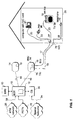
- FIG. 1 a broadband access system for delivery of video, data (for a computer network interface) and telephony services is shown.
- a broadband access system for delivery of video, data (for a computer network interface) and telephony services is shown.
- techniques disclosed herein may be used in connection with other services/technologies, the preferred embodiment will be discussed in connection with the delivery and distribution of digital video signals. Components used for these other services are not needed to understand the subject invention, and are only described to the extent their presence may be pertinent to the understanding of the subject invention.
- the digital broadband access system typically includes a broadband digital terminal (BDT) 12 connected to a broadband network unit (BNU) 14.
- BDT broadband digital terminal
- BNU broadband network unit
- the BDT 12 can be equipped with an element management system (EMS) 13 that provisions services and equipment, and for handling certain video signal controls on the digital broadband access system.
- EMS 13 is usually software based and can be implemented on either a personal computer or a workstation.
- a personal computer based EMS can support one BDT 12 and its associated broad access network equipment.
- a workstation can support multiple BDT's 12 and their respective access network equipment.
- video programming is primarily input to the broadband access system via an Asynchronous Transfer Mode (ATM) network 26 connected to the BDT 12.
- ATM Asynchronous Transfer Mode
- the BDT 12, through communication with a Channel Bank (CB) 30 can also receive special services signals from private networks or non-switched public networks 32 for transmission through the broadband access system via a connection with a special networks-CB interface 34.
- the CB 30 is connected to the BDT 12 allowing customers to order programming from the special private or public networks.
- the interface to the ATM network-BDT interface 39 can be realized using an OC-3 or OC-12 optical interfaces carrying ATM cells.
- BDT 12 has two OC-12c broadcast ports, which can only receive signals carrying ATM cells, and one OC-12c interactive port which can receive and transmit signals.
- the BDT 12 can also be connected to the Public Switched Telecommunications Network (PSTN) 70.
- PSTN Public Switched Telecommunications Network
- the physical interface to the PSTN is twisted wire pairs supporting the transmission of DS-1 signals, or optical fiber supporting the transmission of OC-3 optical signals.
- the BDT 12 is typically located in a facility owned by the video/data service provider, for example, the central office of a Regional Bell Operating Company.
- the BNU 14 is located in the serving area usually on a telephone pole (i.e., at the "curb") proximate the houses 29 of the subscribers.
- the preferred connection between the BDT 12 and BNU 14 is made with an optical fiber cable 16 and is sometimes called a fiber-to-the-curb (FTTC) architecture.
- FTTC fiber-to-the-curb
- the FTTC architecture is an outgrowth of Digital Loop Carrier (DLC) technology which was developed in the early 1970's to provide telephone service to areas remotely located from a telephone company's central office. Capable of utilizing digital switching, the FTTC architecture has the advantage of being compatible with both isochronous telephone network and packet/cell based network and is thus well suited for providing Internet access and Switched Digital Video (SDV).
- DLC Digital Loop Carrier
- the optical fiber 16 is a single-mode fiber and a dual wavelength transmission scheme is used to transmit signals between BDT 12 and BNU 14. Digital signals pass back and forth between BDT 12 and BNU 14 at a rate of 155Mb/s utilizing Synchronous Digital Hierarchy (SDH).
- SDH Synchronous Digital Hierarchy
- the BDT 12 can be connected to scores of BNU's, but the actual number depends on the services offered and the number of subscribers being served. In a preferred embodiment, up to sixty-four BNU's are served by each BDT 12.
- Each BNU 14 has multiple drops for serving a plurality of subscribers. Typically, each BNU 14 can serve sixteen subscribers' houses 29.
- the drops for delivering video services are preferably coaxial cable 17. (Although optical fiber may be used to deliver the video signals from the BIU 15 to each subscriber's house 29, the preferred connection is made with coaxial cable 17 for economic reasons.)
- a broadband interface unit (BIU) 15 is needed to convert the digital signals delivered to the BNU 14 by the optical fiber cable 16 into analog signals.
- the broadband interface unit 15 is located within BNU 14 and generates broadband signals which contain video, data and voice information.
- the BIU 15 ultimately communicates with various devices inside the subscriber's house 29. These may include Premises Interface Devices 96, Network Interface Cards 91 and television set-top units 19.
- BIU 15 modulates data onto an RF carrier and transmits the data over the coaxial drop cable 17.
- the BIU 15 is connected to the set-top unit 19, either directly or through a splitter 27 as shown in FIG. 1 .
- the splitter 27 is used when the broadband access system is utilized to deliver other services (e.g., high speed Internet access and/or telephony), in addition to video, to the subscriber or to provide signals to multiple set-top units.
- the connection between splitter 27 and the various devices within the subscriber's home 29 is preferably made with an in-home coaxial wiring 33.
- an interface subsystem including an active device sometimes referred to as a "residential gateway" (in contrast to the passive splitter 27), may be used to control and direct the various services within the subscriber's home 29, and to convert signals received from BIU 15 to the appropriate format required by each device.
- In-home coaxial wiring 33 connects set-top unit 19 with splitter 27.
- the set-top unit 19 is connected to a television 39 in the normal manner. If the signals generated by BIU 15 are still not compatible with a specific television unit 39, the set-top 19 may include additional circuitry that converts the video signals from the BIU to signals compatible with any television 39 present in the home 29.
- the BNU 14 may contain a Telephone Interface Unit (TIU) 75 which generates an analog Plain Old Telephony (POT) signal.
- a twisted wire pair drop 18 is shown in FIG. 1 for delivering traditional narrowband Plain Old Telephony (POT) service to all subscribers.
- the subscriber's telephone 79 is preferably connected to the TIU 75 through a Network Interface Device 78. If the deployment scenario is such that construction considerations prohibit the installation of coaxial cable drops 17, the relatively recent developments in transmission line technologies (e.g., High Speed Digital Subscriber Line, Asymmetric Digital Subscriber Line, and Very High Rate Digital Subscriber Line, sometimes each is referred to as xDSL technologies) allow high speed services to be delivered over the twisted wire pair 18.
- xDSL technologies allow high speed services to be delivered over the twisted wire pair 18.
- a cable box i.e., a type of set-top unit used by cable TV service providers.
- the subscriber accesses the cable box/set-top unit.
- the cable box actually performs the channel changing and decryption of the incoming video signals.
- the actual changing of the channel is performed by circuitry 10 within the BDT 12 or BNU 14, and only one or two video channels at a time are typically delivered to the subscriber's set top unit 19.
- the video service provider controls the delivery of the video signal at a point upstream from the subscriber, it reduces the possibility that the subscriber can tamper with the system and reduces theft of services. This, in turn, eliminates the need for encryption of the video signal and further reduces the complexity of set-top units.
- the subscriber By locating the channel changing circuitry at a distance away from the subscriber's television, the subscriber experiences a delay in time between each channel change on his television. As the following example will show, in which the subscriber changes the channel viewed on television set 39 to channel X, an unacceptable delay may be caused.
- FIG. 2A illustrates the initial transmission of the control signals between the set-top unit 19 and the BDT 12 when a subscriber makes a request for a change of channel to channel X.
- the set-top unit 19 sends a request for channel change to channel X to the BDT 12 over the broadband access system as illustrated by the control plane in FIG. 2A .
- the BDT 12 After receiving the request from the set-top unit 19, the BDT 12 must then determine if it is a proper request and, if proper, acknowledge the set top unit 19 with a confirmation signal sent over the access system. (See FIG. 2A again.) When the BDT synchronizes with channel X, it must then direct the corresponding video data downstream to the appropriate set top unit 19 as illustrated by the user/service plane of FIG. 2B .
- FIG. 1 the illustrations of Figs. 2A and 2B of the signal transmissions over the broadband access system show the relative travel of, and number of, signals being transmitted between a single set-top unit and a BDT 12, one must refer back to FIG. 1 to fully appreciate the time delay incurred in a "typical" channel change request.
- the subscriber must communicate his request to change to new channel X to the set-top unit 19; this is usually done through the use of a common infrared remote control.
- the request for channel X must travel upstream from the set-top unit 19 to the BIU 15.
- the control signal must be received by the BIU and passed to the BNU 14.
- the BNU 14 bundles all of the received control signals from the multiple set-top units it serves and transmits them to the BDT.
- the BDT 12, under control of the EMS 13, must determine if the channel change request is valid and if that particular subscriber has paid for the requested service.
- the BDT will acknowledge receipt of the change of channel request. This is done through the BDT 12, under control of the EMS 13, by generating a confirmation signal to change to channel X back down the fiber optic cable to the BNU 14. The BNU 14 then directs the confirmation signal to the appropriate set-top unit. Meanwhile, the BDT 12 must then synchronize with channel X as it is received from the ATM network. Channel X is decompressed, and then multiplexed with the other video signals corresponding to the channels requested by the various other subscribers. Once BNU 14 receives the multiplexed signal, it is demultiplexed and the appropriate signal is directed to the set-top units of the appropriate requesting subscribers.
- Asynchronous Transfer Mode (ATM) network was designed with the flexibility to meet the needs of many types of user data with a single format.
- the data transmitted over an ATM system can include digital video, digitized voice, computer data and transaction information (such as between an automated banking machine and a central computer) over both local and wide area networks.
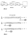
- the ATM format does not specify data rates or a physical channel, but calls for relatively short bit segments. Specifically, the ATM format calls for a fifty-three byte cell format, as shown in FIG. 3 , which allocates five bytes for overhead and forty-eight bytes for actual data. The utilization of a short bit segment is important when the mixture of data signals include computer data.
- the cell format for systems that handle computer data is relatively long. This would be unacceptable for "mixed" systems that transmit "real-time" signals such as video and voice.
- the short cell format of the ATM systems ensures that traffic from real-time sources do not have to wait an extraordinary period of time before they can be sent between the computer data cells.
- the five byte header of an ATM cell contains all of the information needed to relay the cell from one node to the next node, over a pre-established route.
- the video data is contained in the forty-eight byte information field.
- a compression scheme is preferably utilized to pack more video data into each information field.
- Virtually all of the compression schemes require a starting or synchronization frame usually referred to as the Group of Picture (GOP) start point.
- GOP Group of Picture
- the GOP start point is found proximate the beginning of the information field as illustrated in FIG. 3 .
- the BDT 12 After receiving the request from a subscriber to change to a new channel, the BDT 12 must then wait for the Group of Picture (GOP) start point of the requested channel.
- GOP Group of Picture
- the time between GOP start points is significant. As illustrated in FIG. 4 , the time delay between GOP B1 and GOP B2 may be 1 ⁇ 2 second or more depending on the compression scheme and other factors.
- the BDT 12 After the BDT 12 synchronizes with the appropriate GOP start point, it can then decompress the requested signal and direct it to the subscriber(s) who have requested it.
- the signal corresponding to the requested channels is then multiplexed with the signals corresponding to the requested channel of all other subscribers handled by that BDT 12.
- the multiplexed signal is then transmitted downstream to BNU 14, where the signal is demuxed and directed to the appropriate set-top units 19.
- the compressed format used to encode the video data is the Moving Pictures Experts Group 2 format, known as MPEG-2.
- MPEG-2 Moving Pictures Experts Group 2 format
- the data is transmitted as one of three basic frames.
- the GOP start point is coded in the "I" or intracoded frames.
- I frames In addition to the I frames, there are predicted frames and bidirectional frames (P and B frames, respectively).
- P and B frames normally contain the video and audio content.
- Each synchronization frame is separated from the next synchronization frame by a pre-determined number of other frames. This predetermined number can be set to accommodate a specific requirement but in one preferred embodiment is fifteen frames.
- the MPEG-2 cells comprise video data in P or B frames between synchronization or I frames.
- the MPEG-2 cells of a particular video channel may be transmitted in a individual ATM cell or the MPEG-2 cells of multiple video channels may be multiplexed onto an ATM cell or cells.
- the time between I frames under the embodiment utilizing MPEG-2 is approximately 1 ⁇ 2 second. Therefore, depending on when the BDT receives a channel change request, there can be up to a 1 ⁇ 2 second delay just for the BDT to synchronize with the I frame. Additional time must be allowed for the request to reach the BDT from the set-top, acknowledgment of the request, and eventually for transmission of the requested video signal back to the subscriber's set-top that made the request.
- the BDT 12 is connected to a video source (ATM network 26 or special network 34) that provide a plurality of compressed video signals.
- the compressed video signals are transmitted using the MPEG-2 format which utilizes a synchronization frame called the intracoded or "I" frame.
- I a synchronization frame
- digital video delivery systems in contrast with analog systems, require a synchronization or start frame.
- the I frame is transmitted about every 1 ⁇ 2 second in MPEG-2. Accordingly, it may take over a second between the time a subscriber bequests a certain channel and can then actually view the requested channel on the television 39. The largest portion of the one second delay is caused by the wait for the video processor in the BDT to synchronize with the next available I frame.
- the subject rapid channel changer 10 is designed to minimize any delay between a subscriber's request to change a television channel and the actual delivery of the signal corresponding to the desired channel.
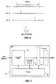
- the subject invention 10 includes a first-in-first-out (FIFO) buffer 50 for storing the compressed video data of each video channel, and a processor 55 for indexing the synchronization frames.
- FIFO first-in-first-out
- the processor 55 detects the GOP start frame (or I frame in the preferred embodiment) for each channel received and establish a pointer for each GOP start frame. The processor 55 then records the I frame pointer location for each channel in a second buffer 57.
- FIFO buffer 50 As new video information is received into FIFO buffer 50, the previous information is counted out.
- the FIFO buffer 50 must hold at least the minimum number of frames in the compression scheme so that at least one GOP frame for each video channel is stored at all times in the buffer. Therefore as one I frame for channel X leaves the FIFO buffer a new I frame must enter (see FIG. 5 ).
- the processor detects the new I frame and records the new pointer location for future reference.
- the FIFO buffer 50 of the rapid channel changer 10 stores, at a minimum, fifteen frames (i.e., one I frame and fourteen P or B frames) for each channel that is received by the BDT.
- multiple buffer memory units may be used, e.g., one for each video channel.
- the processor detects each I frame as it enters the buffer and keeps track of its position as it moves through the buffer (i.e., indexing the I frame).
- the requested signal can instantly be transmitted downstream to the subscriber since the processor 55 is always "pointing" to an I frame for each respective channel. Accordingly, the largest portion of the channel changing delay - up to a 1 ⁇ 2 second that the processor had to wait for the next synchronization frame - is eliminated.
- the processor can immediately look up the location of the I frame from the pointer location buffer 57 and immediately accesses the appropriate video data.
- the BDT then sends a stream of data from the FIFO buffer 50 to a multiplexer 44 to generate a multiplexed signal for transmission to BNU 14.
- a FIFO buffer 50 for each compressed video signal is desirable.
- a subscriber may have forty channels from which to choose; therefore, forty channels may be sent from the ATM network 26 to the BDT 12. Accordingly, forty FIFO buffers 50 will be used for this example of the rapid channel changer 10.
- the FIFO buffer may be desirable for the FIFO buffer to store two or more synchronization frames per video signal (i.e., each buffer stores at least thirty frames in the aforementioned MPEG-2 embodiment utilizing fifteen frames in each cell). In this manner, the BDT 12 can direct different channel requests to thousands of subscribers regardless of the actual location of the synch frame on any broadcast video signal.
- a signal is sent to the set-top unit 19 and travels upstream through the BNU 14 to the BDT 12.
- the I frame of buffer 50 is accessed by microprocessor 55.
- the processor 55 has stored the information corresponding to intracoded frame I x .
- the processor 55 stores the position of the next intracoded frame I x+1 .
- the processor 55 keeps continuous track of the I frame. Accordingly, the processor 55 can immediately synchronize with the video signal stored in the FIFO buffer 50. Since the processor 55 can immediately synchronize with the video signal, it can substantially simultaneously direct the desired video data from FIFO buffer 50 to the multiplexer 44 for eventual transmission downstream to the subscriber.
- the BDT may also determine whether the requested channel is already being transmitted to the requesting BNU. If so, there may be no need to transmit an additional signal with the same video channel information. The BNU will replicate the signal and send it to the second requesting subscriber.
- the video channel buffers and processor may be located in BNU 14, if desired.
- the invention is intended to be protected broadly within the scope of the appended claims.
Landscapes
- Engineering & Computer Science (AREA)
- Multimedia (AREA)
- Signal Processing (AREA)
- Data Exchanges In Wide-Area Networks (AREA)
- Two-Way Televisions, Distribution Of Moving Picture Or The Like (AREA)
- Compression Or Coding Systems Of Tv Signals (AREA)
Claims (12)
- Verfahren zum Wechseln zu einem von einem Teilnehmer in einem geschalteten digitalen Videosystem angeforderten Kanal, wobei das Verfahren die folgenden Schritte aufweist:Eingabe komprimierter Videodaten, welche einer Vielzahl von videokanälen entsprechen, in eine erste Speichervorrichtung, welche einen Pufferspeicher von der Art eines FIFO-(first-in-first-out)-Speichers aufweist, wobei die Videodaten mindestens einen Group of Pictures (GOP) Startframe für jeden Videokanal aufweisen;Erfassung des Group of Pictures oder GOP-Startframes für jeden Eingabe-Videokanal;Aufzeichnung der Standorte der erfassten Group of Pictures oder GOP-Startframes in einer zweiten Speichervorrichtung;Empfang einer Anfrage nach einem Videokanal von einem Teilnehmer;Zugriff auf einen komprimierten Videodatenstrom in der ersten Speichervorrichtung, welcher dem angeforderten Videokanal an dem Group of Pictures Startframe-Standort entspricht, welcher in der zweiten Speichervorrichtung aufgezeichnet ist; undÜbertragung des aufgerufenen Stroms komprimierter Videodaten, welche dem angeforderten Kanal entsprechen, an den anfordernden Teilnehmer.
- Verfahren nach Anspruch 1, dadurch gekennzeichnet, dass die Videodaten in MPEG2- Format vorlieben.
- Verfahren nach Anspruch 1, dadurch gekennzeichnet, dass der aufgerufene Videodatenstrom mit anderen Videoströmen zur Übertragung an eine Vielzahl von Teilnehmern gebündelt bzw. multiplext wird.
- Verfahren nach Anspruch 1, dadurch gekennzeichnet, dass nach Empfang der videokanalanfrage, das Verfahren des Weiteren den Schritt der Bestätigung dieser Anfrage aufweist.
- Kanalwechsler zum wechseln zu einem von einem Teilnehmer angeforderten Videokanal in einem geschalteten digitalen videosystem, wobei der Kanalwechsler komprimierte videodaten empfängt, welche einer Vielzahl von Videokanälen aufweisen, wobei der Kanalwechsler Folgendes aufweist:eine erste Speichervorrichtung, welche einen Pufferspeicher von der Art eines FIFO-Speichers aufweist, zur Speicherung der komprimierten Videodaten, wobei die komprimierten Videodaten mindestens einen Group of Pictures oder GOP-Startframe für jeden Videokanal einschießen;eine Vorrichtung zur Erfassung der Group of Pictures oder GOP-Startframes für jeden videokanal;eine zweite Speichervorrichtung zur Aufzeichnung der Standorte der erfassten Group of Pictures oder GOP-Startframes;eine Empfangsvorrichtung für den Empfang einer Anfrage nach einem Videokanal von einem Teilnehmer;eine Vorrichtung zum Zugreifen auf einen Strom komprimierter Videodaten, welche dem angeforderten Videokanal an dem Group of Pictures oder GOP-Startframe entsprechen; undeine Vorrichtung zur Übertragung der aufgerufenen komprimierten Videodaten, welche dem angeforderter Videokanal entsprechen, an einen anfordernden Teilnehmer.
- Kanalwechsler nach Anspruch 5, dadurch gekennzeichnet, dass die empfangenen komprimierten Videodaten in MPEG2-Format vorliegen und der Group of Pictures oder GOP-Startframe ein intracodierter Frame ist.
- Kanalwechsler nach Anspruch 5, dadurch gekennzeichnet, dass die Erfassungsvorrichtung eine Prozessorvorrichtung und die zweite Speichervorrichtung eine Pufferspeichervorrichtung zum Speichern des augenblicklichen Standorts des Group of Pictures oder GOP-Startframes ist.
- Kanalwechsler nach Anspruch 5, welcher des Weiteren Folgendes aufweist:eine Vorrichtung zur Bestätigung der Anfrage.
- Kanalwechsler nach Anspruch 5, dadurch gekennzeichnet, dass die Zugriffsvorrichtung eine Prozessorvorrichtung ist.
- Digitales videosystem, welches einen Kanalwechsler gemäß Anspruch 5 sowie eine Breitband-Netzwerkeinheit (BNU) zur Leitung der Videodaten an eine Vielzahl von Teilnehmern aufweist.
- Digitales Videosystem nach Anspruch 10, dadurch gekennzeichnet, dass der Kanalwechsler mit der BNU über eine Telekommunikationsverbindung, welche einen Lichtleiter aufweist, verbunden ist.
- Digitales Videosystem nach Anspruch 11, welches eine vielzahl von Breitband-Netzwerkeinheiten BNUs aufweist.
Applications Claiming Priority (3)
| Application Number | Priority Date | Filing Date | Title |
|---|---|---|---|
| US915467 | 1986-10-06 | ||
| US08/915,467 US6728965B1 (en) | 1997-08-20 | 1997-08-20 | Channel changer for use in a switched digital video system |
| PCT/US1998/013755 WO1999009741A1 (en) | 1997-08-20 | 1998-06-30 | Channel changer for use in a switched digital video system |
Publications (3)
| Publication Number | Publication Date |
|---|---|
| EP1004201A1 EP1004201A1 (de) | 2000-05-31 |
| EP1004201A4 EP1004201A4 (de) | 2006-08-23 |
| EP1004201B1 true EP1004201B1 (de) | 2009-01-07 |
Family
ID=25435801
Family Applications (1)
| Application Number | Title | Priority Date | Filing Date |
|---|---|---|---|
| EP98931769A Expired - Lifetime EP1004201B1 (de) | 1997-08-20 | 1998-06-30 | Kanalwechsler zur benutzung in einem geschaltetem digitalem videosystem |
Country Status (8)
| Country | Link |
|---|---|
| US (1) | US6728965B1 (de) |
| EP (1) | EP1004201B1 (de) |
| JP (1) | JP2001516184A (de) |
| AU (1) | AU754525B2 (de) |
| CA (1) | CA2300879C (de) |
| DE (1) | DE69840446D1 (de) |
| TW (1) | TW388182B (de) |
| WO (1) | WO1999009741A1 (de) |
Families Citing this family (79)
| Publication number | Priority date | Publication date | Assignee | Title |
|---|---|---|---|---|
| US7448063B2 (en) | 1991-11-25 | 2008-11-04 | Actv, Inc. | Digital interactive system for providing full interactivity with live programming events |
| US7079176B1 (en) | 1991-11-25 | 2006-07-18 | Actv, Inc. | Digital interactive system for providing full interactivity with live programming events |
| US6591013B1 (en) * | 1999-03-22 | 2003-07-08 | Broadcom Corporation | Switching between decoded image channels |
| US6721794B2 (en) | 1999-04-01 | 2004-04-13 | Diva Systems Corp. | Method of data management for efficiently storing and retrieving data to respond to user access requests |
| SE520746C2 (sv) * | 1999-05-17 | 2003-08-19 | Omicron Ceti Ab | Anordning för kanalomkoppling i ett digitalt TV- mottagningssystem |
| US7380266B1 (en) * | 1999-09-09 | 2008-05-27 | Agere Systems Inc. | Transmission method and apparatus for optical fiber television network |
| EP1224643B1 (de) * | 1999-10-28 | 2006-10-04 | NCube Corporation | System mit adaptiver bandbreite und verfahren für datenrundsendung |
| CN1244080C (zh) | 1999-10-28 | 2006-03-01 | 美国安科公司 | 带宽动态分配方法 |
| US6985188B1 (en) | 1999-11-30 | 2006-01-10 | Thomson Licensing | Video decoding and channel acquisition system |
| AU4711701A (en) * | 1999-12-09 | 2001-06-18 | Liberate Technologies, Morecom Division, Inc. | Method and apparatus for two-way internet access over network a catv with channel tracking |
| US7305691B2 (en) | 2001-05-07 | 2007-12-04 | Actv, Inc. | System and method for providing targeted programming outside of the home |
| CA2473475C (en) | 2002-02-04 | 2017-04-25 | Imagine Broadband Limited | Media transmission system and method |
| US8161510B2 (en) * | 2002-04-08 | 2012-04-17 | Thomson Licensing | Apparatus and method for data caching to reduce channel change delay |
| KR100454958B1 (ko) * | 2002-04-18 | 2004-11-06 | 삼성전자주식회사 | 디지털 방송 서비스에서의 채널 변경 방법 |
| US8843990B1 (en) * | 2002-04-25 | 2014-09-23 | Visible World, Inc. | System and method for optimized channel switching in digital television broadcasting |
| US7075899B2 (en) | 2002-05-21 | 2006-07-11 | Actv, Inc. | System and method for providing private in-band data to digital set-top boxes in a broadcast environment |
| US8397269B2 (en) * | 2002-08-13 | 2013-03-12 | Microsoft Corporation | Fast digital channel changing |
| US7523482B2 (en) * | 2002-08-13 | 2009-04-21 | Microsoft Corporation | Seamless digital channel changing |
| US20040060074A1 (en) * | 2002-09-19 | 2004-03-25 | Ganesh Basawapatna | Video distribution system with increased centralized processing |
| US6970169B1 (en) * | 2002-09-24 | 2005-11-29 | Adobe Systems Incorporated | Digitally synthesizing seamless texture having random variations |
| US7690022B2 (en) * | 2002-10-02 | 2010-03-30 | Ganesh Basawapatna | Video distribution system for digital and analog subscribers |
| US7380265B2 (en) * | 2002-10-16 | 2008-05-27 | The Directv Group, Inc. | System for monitoring direct broadcast wireless signals |
| US7603689B2 (en) * | 2003-06-13 | 2009-10-13 | Microsoft Corporation | Fast start-up for digital video streams |
| JP3883986B2 (ja) * | 2003-06-17 | 2007-02-21 | 三洋電機株式会社 | デジタルテレビ放送受信機 |
| US9807460B2 (en) | 2003-08-11 | 2017-10-31 | Arris Enterprises, Inc. | Optimal provisioning and management of bandwidth in a video-on-demand services architecture |
| US7443791B2 (en) | 2003-10-10 | 2008-10-28 | Microsoft Corporation | Priority mechanism for distributed sending of media data |
| US7562375B2 (en) * | 2003-10-10 | 2009-07-14 | Microsoft Corporation | Fast channel change |
| US7516232B2 (en) | 2003-10-10 | 2009-04-07 | Microsoft Corporation | Media organization for distributed sending of media data |
| US7444419B2 (en) * | 2003-10-10 | 2008-10-28 | Microsoft Corporation | Media stream scheduling for hiccup-free fast-channel-change in the presence of network chokepoints |
| US7545812B2 (en) | 2003-10-10 | 2009-06-09 | Microsoft Corporation | Scheduling scheme for distributed sending of media data |
| US7614071B2 (en) | 2003-10-10 | 2009-11-03 | Microsoft Corporation | Architecture for distributed sending of media data |
| JP2005204273A (ja) * | 2003-12-15 | 2005-07-28 | D & M Holdings Inc | Avシステム及びav機器並びに映像信号出力方法 |
| US8566469B2 (en) * | 2003-12-24 | 2013-10-22 | Intel Corporation | Method and system for predicting and streaming content utilizing multiple stream capacity |
| US7430222B2 (en) * | 2004-02-27 | 2008-09-30 | Microsoft Corporation | Media stream splicer |
| US8249113B2 (en) * | 2004-03-19 | 2012-08-21 | Broadlogic Network Technologies, Inc. | Method and system for providing faster channel switching in a digital broadcast system |
| DE102004026170A1 (de) * | 2004-05-28 | 2005-12-22 | Siemens Ag | Verfahren und Anordnung zur Auswahl abrufbarer Informationen |
| FR2871649B1 (fr) * | 2004-06-10 | 2006-09-22 | Mediasyscom Soc Par Actions Si | Procede de commutation de programmes video numeriques et emetteur pour sa mise en oeuvre |
| US20060020995A1 (en) * | 2004-07-20 | 2006-01-26 | Comcast Cable Communications, Llc | Fast channel change in digital media systems |
| KR100703682B1 (ko) * | 2004-08-27 | 2007-04-05 | 삼성전자주식회사 | 디지털 방송 수신기에서 채널 절환 지연 시간을감소시키는 방법 및 그 방법을 사용하는 디지털 방송 수신기 |
| ATE477679T1 (de) * | 2004-09-16 | 2010-08-15 | Alcatel Usa Sourcing Lp | Abknallendmittel mit verbesserter latenz |
| US7640352B2 (en) * | 2004-09-24 | 2009-12-29 | Microsoft Corporation | Methods and systems for presentation of media obtained from a media stream |
| US20060075428A1 (en) * | 2004-10-04 | 2006-04-06 | Wave7 Optics, Inc. | Minimizing channel change time for IP video |
| KR100685992B1 (ko) * | 2004-11-10 | 2007-02-23 | 엘지전자 주식회사 | 디지털 방송 수신기에서 채널 전환시 정보 출력 방법 |
| JP4901751B2 (ja) * | 2004-12-06 | 2012-03-21 | トムソン ライセンシング | ディジタル・ネットワークにおけるマルチプル・クローズド・キャプション・フローおよびカスタマー・アクセス |
| US7477653B2 (en) * | 2004-12-10 | 2009-01-13 | Microsoft Corporation | Accelerated channel change in rate-limited environments |
| US8204131B2 (en) * | 2005-01-13 | 2012-06-19 | Qualcomm Incorporated | Method and system for rapid and smooth selection of digitally compressed video programs |
| CN100592790C (zh) * | 2005-03-07 | 2010-02-24 | 艾利森电话股份有限公司 | 多媒体信道切换 |
| WO2006096104A1 (en) * | 2005-03-07 | 2006-09-14 | Telefonaktiebolaget Lm Ericsson (Publ) | Multimedia channel switching |
| US7668914B2 (en) * | 2005-03-28 | 2010-02-23 | Alcatel Lucent | Milestone synchronization in broadcast multimedia streams |
| US7804831B2 (en) * | 2005-04-01 | 2010-09-28 | Alcatel Lucent | Rapid media channel changing mechanism and access network node comprising same |
| EP1768347A1 (de) * | 2005-09-21 | 2007-03-28 | Alcatel | Gerät zur Aufnahme von Rundfunkprogrammen |
| DE102005046382A1 (de) * | 2005-09-28 | 2007-04-05 | Siemens Ag | Verfahren, Kommunikationsanordnung und dezentrale Kommunikationseinrichtung zum Übermitteln von Multimedia-Datenströmen |
| US20070110503A1 (en) * | 2005-10-31 | 2007-05-17 | Glover J S | Dispensing brush with replaceable cartridge/handle part |
| US7873760B2 (en) * | 2005-11-11 | 2011-01-18 | Versteeg William C | Expedited digital signal decoding |
| US8135040B2 (en) * | 2005-11-30 | 2012-03-13 | Microsoft Corporation | Accelerated channel change |
| US8630306B2 (en) * | 2006-01-09 | 2014-01-14 | At&T Intellectual Property I, L.P. | Fast channel change apparatus and method for IPTV |
| KR100768950B1 (ko) | 2006-01-11 | 2007-10-19 | 삼성전자주식회사 | 채널전환시간을 최소화하는 디지털방송수신장치 및 그의채널전환방법 |
| EP1811780B1 (de) | 2006-01-24 | 2012-11-07 | Alcatel Lucent | Routingknote mit Pufferfunktion für Videokanäle |
| US8028319B2 (en) * | 2006-05-31 | 2011-09-27 | At&T Intellectual Property I, L.P. | Passive video caching for edge aggregation devices |
| JP4256882B2 (ja) * | 2006-06-19 | 2009-04-22 | 株式会社エヌ・ティ・ティ・ドコモ | 基地局、映像配信システム及び配信制御方法 |
| KR100762667B1 (ko) | 2006-06-30 | 2007-10-01 | 삼성전자주식회사 | 빠른 채널 전환이 가능한 디지털 방송 수신 장치 및 그방법 |
| WO2008055712A1 (en) * | 2006-11-10 | 2008-05-15 | Telefonaktiebolaget Lm Ericsson (Publ) | Providing iptv multicasts |
| US7849490B2 (en) * | 2007-03-12 | 2010-12-07 | Cisco Technology, Inc. | Method and apparatus providing scalability for channel change requests in a switched digital video system |
| US8370889B2 (en) * | 2007-03-28 | 2013-02-05 | Kanthimathi Gayatri Sukumar | Switched digital video client reverse channel traffic reduction |
| US20080271076A1 (en) * | 2007-04-27 | 2008-10-30 | General Instrument Corporation | Method and Apparatus for Switching Between Edge Device Resources in an SDV System |
| US8832766B2 (en) * | 2007-07-27 | 2014-09-09 | William C. Versteeg | Systems and methods of differentiated channel change behavior |
| US8776160B2 (en) | 2007-07-27 | 2014-07-08 | William C. Versteeg | Systems and methods of differentiated requests for network access |
| US20090106807A1 (en) * | 2007-10-19 | 2009-04-23 | Hitachi, Ltd. | Video Distribution System for Switching Video Streams |
| US8141123B2 (en) * | 2007-12-19 | 2012-03-20 | General Instrument Corporation | Method and apparatus for recording and rendering programs that cross SDV force tune boundaries |
| US7886073B2 (en) | 2008-08-08 | 2011-02-08 | Cisco Technology, Inc. | Systems and methods of reducing media stream delay |
| US8015310B2 (en) | 2008-08-08 | 2011-09-06 | Cisco Technology, Inc. | Systems and methods of adaptive playout of delayed media streams |
| US8239739B2 (en) | 2009-02-03 | 2012-08-07 | Cisco Technology, Inc. | Systems and methods of deferred error recovery |
| EP2378758A1 (de) * | 2010-04-09 | 2011-10-19 | Alcatel-Lucent España, S.A. | Verfahren zur Rundfunksendung von Multimediainhalt |
| GB2490659A (en) | 2011-05-04 | 2012-11-14 | Nds Ltd | Fast channel change using channel packs comprising independently decodable frame segments having differing qualities |
| GB2493498A (en) | 2011-07-18 | 2013-02-13 | Nds Ltd | Fast channel change using an aggregated video service |
| US9015555B2 (en) | 2011-11-18 | 2015-04-21 | Cisco Technology, Inc. | System and method for multicast error recovery using sampled feedback |
| US10349105B2 (en) * | 2016-11-14 | 2019-07-09 | Arris Enterprises Llc | Channel change processing using stored content |
| WO2019050067A1 (ko) * | 2017-09-08 | 2019-03-14 | 라인 가부시키가이샤 | 비디오 품질 제어 |
| US10531132B2 (en) * | 2017-12-28 | 2020-01-07 | Stmicroelectronics International N.V. | Methods and techniques for reducing latency in changing channels in a digital video environment |
Family Cites Families (12)
| Publication number | Priority date | Publication date | Assignee | Title |
|---|---|---|---|---|
| US5724091A (en) * | 1991-11-25 | 1998-03-03 | Actv, Inc. | Compressed digital data interactive program system |
| US5216503A (en) * | 1991-12-24 | 1993-06-01 | General Instrument Corporation | Statistical multiplexer for a multichannel image compression system |
| JP3104953B2 (ja) * | 1993-12-17 | 2000-10-30 | 日本電信電話株式会社 | 多重読み取り特殊再生方法 |
| US5422674A (en) * | 1993-12-22 | 1995-06-06 | Digital Equipment Corporation | Remote display of an image by transmitting compressed video frames representing background and overlay portions thereof |
| US5629732A (en) | 1994-03-29 | 1997-05-13 | The Trustees Of Columbia University In The City Of New York | Viewer controllable on-demand multimedia service |
| US5720037A (en) * | 1994-06-16 | 1998-02-17 | Lucent Technologies Inc. | Multimedia on-demand server |
| EP0702493A1 (de) * | 1994-09-19 | 1996-03-20 | International Business Machines Corporation | Interaktive Video-Wiedergabe |
| US5659539A (en) * | 1995-07-14 | 1997-08-19 | Oracle Corporation | Method and apparatus for frame accurate access of digital audio-visual information |
| JPH0946547A (ja) * | 1995-07-31 | 1997-02-14 | Sony Corp | 映像信号処理装置 |
| JP3445418B2 (ja) * | 1995-08-29 | 2003-09-08 | 三菱電機株式会社 | 端末装置 |
| US5732217A (en) * | 1995-12-01 | 1998-03-24 | Matsushita Electric Industrial Co., Ltd. | Video-on-demand system capable of performing a high-speed playback at a correct speed |
| US5933192A (en) * | 1997-06-18 | 1999-08-03 | Hughes Electronics Corporation | Multi-channel digital video transmission receiver with improved channel-changing response |
-
1997
- 1997-08-20 US US08/915,467 patent/US6728965B1/en not_active Expired - Lifetime
-
1998
- 1998-06-30 EP EP98931769A patent/EP1004201B1/de not_active Expired - Lifetime
- 1998-06-30 WO PCT/US1998/013755 patent/WO1999009741A1/en not_active Ceased
- 1998-06-30 CA CA002300879A patent/CA2300879C/en not_active Expired - Lifetime
- 1998-06-30 DE DE69840446T patent/DE69840446D1/de not_active Expired - Lifetime
- 1998-06-30 JP JP2000510275A patent/JP2001516184A/ja active Pending
- 1998-06-30 AU AU81801/98A patent/AU754525B2/en not_active Ceased
- 1998-11-17 TW TW087113735A patent/TW388182B/zh not_active IP Right Cessation
Also Published As
| Publication number | Publication date |
|---|---|
| EP1004201A4 (de) | 2006-08-23 |
| WO1999009741A1 (en) | 1999-02-25 |
| US6728965B1 (en) | 2004-04-27 |
| EP1004201A1 (de) | 2000-05-31 |
| TW388182B (en) | 2000-04-21 |
| CA2300879A1 (en) | 1999-02-25 |
| DE69840446D1 (de) | 2009-02-26 |
| AU754525B2 (en) | 2002-11-21 |
| JP2001516184A (ja) | 2001-09-25 |
| CA2300879C (en) | 2006-08-08 |
| AU8180198A (en) | 1999-03-08 |
Similar Documents
| Publication | Publication Date | Title |
|---|---|---|
| EP1004201B1 (de) | Kanalwechsler zur benutzung in einem geschaltetem digitalem videosystem | |
| US5594491A (en) | Near-video-on-demand digital video distribution system utilizing asymmetric digital subscriber lines | |
| Chang et al. | An open-systems approach to video on demand | |
| US4994909A (en) | Video signal distribution system | |
| US5583863A (en) | Full service network using asynchronous transfer mode multiplexing | |
| US5793410A (en) | Video pedestal network | |
| US6005865A (en) | Optical network unit for communicating telephony and video information | |
| US5371532A (en) | Communications architecture and method for distributing information services | |
| US5583864A (en) | Level 1 gateway for video dial tone networks | |
| US5029333A (en) | Communications system | |
| US5650994A (en) | Operation support system for service creation and network provisioning for video dial tone networks | |
| EP0450818B1 (de) | Breitband ISDN Paketvermittlungsanordnungen | |
| US5621728A (en) | Level 1 gateway controlling broadband communications for video dial tone networks | |
| US7278152B1 (en) | Video pedestal network | |
| WO2003042795A2 (en) | Streamed content delivery | |
| US6195364B1 (en) | VSDL multiple service provider interface | |
| EP0779739B1 (de) | Architektur und Verfahren zur Bereitstellung von interaktiven breitbandigen Produkten und Diensten unter Verwendung einer vorhandenen Telefonvermittlungsanlage | |
| CA1302554C (en) | Video signal distribution system | |
| KR100921162B1 (ko) | 스트리밍 데이터 전달 시스템에서 물리층 복구 | |
| US6198744B1 (en) | Asynchronous transfer mode (ATM) based very-high-bit-rate digital (VDSL) subscriber line communication system and method | |
| AU699920B2 (en) | Video-on-demand service using ATM cells | |
| Lawrence | Switched simplex high bit rate services in today's residential environment | |
| KR100267865B1 (ko) | 멀티서비스를제공하기위한전송장치 | |
| JP2000101607A (ja) | 放送通信システム | |
| JPH08265728A (ja) | 情報伝送システムにおける送信局、受信端末およびネットワーク |
Legal Events
| Date | Code | Title | Description |
|---|---|---|---|
| PUAI | Public reference made under article 153(3) epc to a published international application that has entered the european phase |
Free format text: ORIGINAL CODE: 0009012 |
|
| 17P | Request for examination filed |
Effective date: 20000317 |
|
| AK | Designated contracting states |
Kind code of ref document: A1 Designated state(s): DE DK ES FI FR GB IE IT LU SE |
|
| A4 | Supplementary search report drawn up and despatched |
Effective date: 20060725 |
|
| RIC1 | Information provided on ipc code assigned before grant |
Ipc: H04N 7/14 20060101ALI20060719BHEP Ipc: H04N 7/10 20060101ALI20060719BHEP Ipc: H04N 7/173 20060101AFI20060719BHEP |
|
| RAP1 | Party data changed (applicant data changed or rights of an application transferred) |
Owner name: NEXT LEVEL COMMUNICATIONS, L.P. |
|
| RAP1 | Party data changed (applicant data changed or rights of an application transferred) |
Owner name: NEXT LEVEL COMMUNICATIONS, INC. |
|
| 17Q | First examination report despatched |
Effective date: 20061208 |
|
| GRAP | Despatch of communication of intention to grant a patent |
Free format text: ORIGINAL CODE: EPIDOSNIGR1 |
|
| GRAS | Grant fee paid |
Free format text: ORIGINAL CODE: EPIDOSNIGR3 |
|
| GRAA | (expected) grant |
Free format text: ORIGINAL CODE: 0009210 |
|
| AK | Designated contracting states |
Kind code of ref document: B1 Designated state(s): DE DK ES FI FR GB IE IT LU SE |
|
| REG | Reference to a national code |
Ref country code: GB Ref legal event code: FG4D |
|
| REG | Reference to a national code |
Ref country code: IE Ref legal event code: FG4D |
|
| REF | Corresponds to: |
Ref document number: 69840446 Country of ref document: DE Date of ref document: 20090226 Kind code of ref document: P |
|
| REG | Reference to a national code |
Ref country code: DE Ref legal event code: R096 Ref document number: 69840446 Country of ref document: DE Effective date: 20090226 |
|
| PG25 | Lapsed in a contracting state [announced via postgrant information from national office to epo] |
Ref country code: FI Free format text: LAPSE BECAUSE OF FAILURE TO SUBMIT A TRANSLATION OF THE DESCRIPTION OR TO PAY THE FEE WITHIN THE PRESCRIBED TIME-LIMIT Effective date: 20090107 Ref country code: ES Free format text: LAPSE BECAUSE OF FAILURE TO SUBMIT A TRANSLATION OF THE DESCRIPTION OR TO PAY THE FEE WITHIN THE PRESCRIBED TIME-LIMIT Effective date: 20090418 |
|
| PG25 | Lapsed in a contracting state [announced via postgrant information from national office to epo] |
Ref country code: SE Free format text: LAPSE BECAUSE OF FAILURE TO SUBMIT A TRANSLATION OF THE DESCRIPTION OR TO PAY THE FEE WITHIN THE PRESCRIBED TIME-LIMIT Effective date: 20090407 |
|
| PG25 | Lapsed in a contracting state [announced via postgrant information from national office to epo] |
Ref country code: DK Free format text: LAPSE BECAUSE OF FAILURE TO SUBMIT A TRANSLATION OF THE DESCRIPTION OR TO PAY THE FEE WITHIN THE PRESCRIBED TIME-LIMIT Effective date: 20090107 |
|
| PLBE | No opposition filed within time limit |
Free format text: ORIGINAL CODE: 0009261 |
|
| STAA | Information on the status of an ep patent application or granted ep patent |
Free format text: STATUS: NO OPPOSITION FILED WITHIN TIME LIMIT |
|
| 26N | No opposition filed |
Effective date: 20091008 |
|
| REG | Reference to a national code |
Ref country code: DE Ref legal event code: R097 Ref document number: 69840446 Country of ref document: DE Effective date: 20091008 |
|
| REG | Reference to a national code |
Ref country code: FR Ref legal event code: ST Effective date: 20100226 |
|
| PG25 | Lapsed in a contracting state [announced via postgrant information from national office to epo] |
Ref country code: IE Free format text: LAPSE BECAUSE OF NON-PAYMENT OF DUE FEES Effective date: 20090630 Ref country code: FR Free format text: LAPSE BECAUSE OF NON-PAYMENT OF DUE FEES Effective date: 20090630 |
|
| PG25 | Lapsed in a contracting state [announced via postgrant information from national office to epo] |
Ref country code: IT Free format text: LAPSE BECAUSE OF FAILURE TO SUBMIT A TRANSLATION OF THE DESCRIPTION OR TO PAY THE FEE WITHIN THE PRESCRIBED TIME-LIMIT Effective date: 20090107 |
|
| PG25 | Lapsed in a contracting state [announced via postgrant information from national office to epo] |
Ref country code: LU Free format text: LAPSE BECAUSE OF NON-PAYMENT OF DUE FEES Effective date: 20090630 |
|
| REG | Reference to a national code |
Ref country code: GB Ref legal event code: 732E Free format text: REGISTERED BETWEEN 20130627 AND 20130703 |
|
| REG | Reference to a national code |
Ref country code: DE Ref legal event code: R082 Ref document number: 69840446 Country of ref document: DE Representative=s name: SPLANEMANN BARONETZKY KNITTER PATENTANWAELTE R, DE |
|
| REG | Reference to a national code |
Ref country code: DE Ref legal event code: R082 Ref document number: 69840446 Country of ref document: DE Representative=s name: SPLANEMANN BARONETZKY KNITTER PATENTANWAELTE R, DE Effective date: 20130918 Ref country code: DE Ref legal event code: R081 Ref document number: 69840446 Country of ref document: DE Owner name: MOTOROLA MOBILITY LLC (N.D. GES. D. STAATES DE, US Free format text: FORMER OWNER: NEXT LEVEL COMMUNICATIONS, INC., ROHNERT PARK, CALIF., US Effective date: 20130918 Ref country code: DE Ref legal event code: R081 Ref document number: 69840446 Country of ref document: DE Owner name: MOTOROLA MOBILITY LLC (N.D. GES. D. STAATES DE, US Free format text: FORMER OWNER: NEXT LEVEL COMMUNICATIONS, INC., ROHNERT PARK, US Effective date: 20130918 Ref country code: DE Ref legal event code: R081 Ref document number: 69840446 Country of ref document: DE Owner name: MOTOROLA MOBILITY LLC (N.D. GES. D. STAATES DE, US Free format text: FORMER OWNER: NEXT LEVEL COMMUNICATIONS, ROHNERT PARK, CALIF., US Effective date: 20081211 |
|
| PGFP | Annual fee paid to national office [announced via postgrant information from national office to epo] |
Ref country code: GB Payment date: 20170627 Year of fee payment: 20 |
|
| REG | Reference to a national code |
Ref country code: GB Ref legal event code: 732E Free format text: REGISTERED BETWEEN 20170831 AND 20170906 |
|
| PGFP | Annual fee paid to national office [announced via postgrant information from national office to epo] |
Ref country code: DE Payment date: 20170628 Year of fee payment: 20 |
|
| REG | Reference to a national code |
Ref country code: DE Ref legal event code: R071 Ref document number: 69840446 Country of ref document: DE |
|
| REG | Reference to a national code |
Ref country code: GB Ref legal event code: PE20 Expiry date: 20180629 |
|
| PG25 | Lapsed in a contracting state [announced via postgrant information from national office to epo] |
Ref country code: GB Free format text: LAPSE BECAUSE OF EXPIRATION OF PROTECTION Effective date: 20180629 |
|
| P01 | Opt-out of the competence of the unified patent court (upc) registered |
Effective date: 20230516 |