EP1004257A1 - Système d'étagères amelioré - Google Patents
Système d'étagères amelioré Download PDFInfo
- Publication number
- EP1004257A1 EP1004257A1 EP99309285A EP99309285A EP1004257A1 EP 1004257 A1 EP1004257 A1 EP 1004257A1 EP 99309285 A EP99309285 A EP 99309285A EP 99309285 A EP99309285 A EP 99309285A EP 1004257 A1 EP1004257 A1 EP 1004257A1
- Authority
- EP
- European Patent Office
- Prior art keywords
- shelf
- leg
- aperture
- assembly according
- support leg
- Prior art date
- Legal status (The legal status is an assumption and is not a legal conclusion. Google has not performed a legal analysis and makes no representation as to the accuracy of the status listed.)
- Withdrawn
Links
- 239000000463 material Substances 0.000 description 3
- 230000004048 modification Effects 0.000 description 3
- 238000012986 modification Methods 0.000 description 3
- 230000008901 benefit Effects 0.000 description 2
- 229920003023 plastic Polymers 0.000 description 2
- 239000004033 plastic Substances 0.000 description 2
- 230000000717 retained effect Effects 0.000 description 2
- 230000004075 alteration Effects 0.000 description 1
- 238000010276 construction Methods 0.000 description 1
- 230000000694 effects Effects 0.000 description 1
- 238000009434 installation Methods 0.000 description 1
- 239000002184 metal Substances 0.000 description 1
- 238000012856 packing Methods 0.000 description 1
Images

Classifications
-
- A—HUMAN NECESSITIES
- A47—FURNITURE; DOMESTIC ARTICLES OR APPLIANCES; COFFEE MILLS; SPICE MILLS; SUCTION CLEANERS IN GENERAL
- A47B—TABLES; DESKS; OFFICE FURNITURE; CABINETS; DRAWERS; GENERAL DETAILS OF FURNITURE
- A47B57/00—Cabinets, racks or shelf units, characterised by features for adjusting shelves or partitions
- A47B57/06—Cabinets, racks or shelf units, characterised by features for adjusting shelves or partitions with means for adjusting the height of the shelves
- A47B57/26—Cabinets, racks or shelf units, characterised by features for adjusting shelves or partitions with means for adjusting the height of the shelves consisting of clamping means, e.g. with sliding bolts or sliding wedges
-
- F—MECHANICAL ENGINEERING; LIGHTING; HEATING; WEAPONS; BLASTING
- F16—ENGINEERING ELEMENTS AND UNITS; GENERAL MEASURES FOR PRODUCING AND MAINTAINING EFFECTIVE FUNCTIONING OF MACHINES OR INSTALLATIONS; THERMAL INSULATION IN GENERAL
- F16B—DEVICES FOR FASTENING OR SECURING CONSTRUCTIONAL ELEMENTS OR MACHINE PARTS TOGETHER, e.g. NAILS, BOLTS, CIRCLIPS, CLAMPS, CLIPS OR WEDGES; JOINTS OR JOINTING
- F16B12/00—Jointing of furniture or the like, e.g. hidden from exterior
- F16B12/44—Leg joints; Corner joints
- F16B12/52—Metal leg connections
Definitions
- the present invention is apparatus for constructing a shelving assembly comprising one or more shelves removably supported upon support legs.
- Preferred embodiments of the present invention seek to overcome the above disadvantages of the prior art.
- a furniture assembly comprising:
- the apparatus may be readily used for the construction of a shelving assembly of one or more shelves supported upon legs and may be designed for packing flat for delivery purposes.
- the apparatus may comprise a single shelf adapted to form a table top but is of particular benefit when designed to be constructed to provide an assembly oftwo or more shelves spaced apart vertically.
- the shelf or shelves will usually be supported upon four legs but additional legs, not necessarily of the same design, may be provided for installation in intermediate positions down the length of the shelf or shelves or, in the case of a table, the latter may be supported upon three legs.
- the or each said support leg is adapted to support the or each said shelf by a respective corner of the or each said shelf.
- Each said bracket comprises two components which cooperate both to retain the adjacent corner between them and also to provide an aperture into which the adjacent leg may pass.
- the or each said shelf preferably includes side walls extending perpendicular to the surface of the shelf, preferably downwardly perpendicular thereto in use.
- the two bracket components may then be designed to be installed to engage the inner and outer faces respectively of the side walls.
- the two components of each mounting bracket are preferably designed to be secured together, for example bolted together, preferably progressively closely, so as to grip the shelf corner between them.
- the two components of the mounting bracket also provide an aperture corresponding closely to the cross-sectional shape and dimension of one of the legs. While one of those components may itself provide such an aperture, it is particularly preferred that at least a part of the or each said aperture is defined by interengaging faces and/or edges of the two components of the corresponding mounting bracket.
- the legs may be of square or circular cross-section, for example.
- the two components of the mounting bracket preferably provide an aperture, preferably an elongate socket, of like cross-section between them.
- the clamping means may advantageously take the form of a shaped member designed to engage the surface of the support leg from the side.
- the shaped member may comprise a jaw, having a profile which in plan view matches a part of the profile of the support leg, for example one corner of a square-cross-sectioned leg or a part of the circumference of a leg of circular cross-section.
- Movement of the clamping means into engagement with the leg may advantageously be effected by tightening a bolt, preferably a threaded bolt.
- the aperture which receives the adjacent support leg is directly defined by the opposed edges or faces of the two components of the mounting bracket
- the bracket components may cooperate to form an aperture of square or rectangular cross-section but the shape of the aperture may be rendered circular or cylindrical by including an appropriately shaped insert between the components.
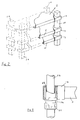
- the apparatus illustrated in Fig. 1 includes a support leg 10 of square cross-section and a shelf 11 formed with a square cut-away corner 12 of a dimension slightly greater than that of the leg 10.
- the shelf is mounted upon the leg by means of a mounting bracket comprising a socket part 13 and an insert 14.
- the socket part 13 of the mounting bracket has an aperture 15 of such a shape and dimensions as to receive the support leg 10 as a close sliding fit. Internal ridges 16 within the part 13 engage the edges 17 formed on the shelf and locate the shelf accurately upon the leg 10.
- the bracket insert 14 is secured within the socket part 13 by means of bolts 18, with the outer leading edges 19 of the insert 14 abutting the adjacent inner faces of the shelf 11. Thus the bracket insert 14 does not make direct contact with the support leg 10. Inter-engagement of the bracket parts 13 and 14 secures the corner of the shelf within the mounting bracket.
- a clamping jaw 20 carried upon a bolt 21, in turn mounted on the bracket insert 14, has a leading edge 22 shaped to match the adjacent corner of the leg 10.
- tightening of the bolt 21 secures the mounting bracket and the shelf upon the support leg. Any adjustment of the height of the shelf 11 upon the leg 10 - or dismantling of the assembly of shelves and legs - merely requires the slackening of the bolt 21.
- Fig. 2 illustrates an assembly ofthree shelves 11 upon support legs 10, each shelfbeing retained upon each leg by means of a mounting bracket such as that illustrated in Fig. 1.
- the modified form of the apparatus illustrated in Fig. 3, includes the leg mounting bracket socket part 13, secured to the shelf 11 in the above-described manner.
- a female tapered insert 26 of square external cross-section but having a tapered cylindrical socket, is secured tightly upon a cylindrical support leg 23 by inter-engagement with a male tapered insert 24, which terminates at its lower end in a hand-operated cam nut 25.
- the thus modified support leg is retained in position within the leg mounting bracket by tightening of the clamping jaw against the adjacent corner ofthe insert 26.
- the only modification which is necessary to mount the shelves in the present invention upon support legs of other than square cross-section is the provision of appropriately shaped inserts such as the illustrated inserts 26 and 24.
- the parts which together make up the apparatus according to the present invention may be formed from any materials suitable for the intended purpose.
- the shelves and all of the other components, apart from the tapered inserts 24 and 26, be made of metal.
- the latter inserts are preferably formed in a plastics material.
- the other components may also be formed in a plastics material if desired.
Landscapes
- Engineering & Computer Science (AREA)
- General Engineering & Computer Science (AREA)
- Mechanical Engineering (AREA)
- Assembled Shelves (AREA)
Applications Claiming Priority (2)
| Application Number | Priority Date | Filing Date | Title |
|---|---|---|---|
| GB9825895 | 1998-11-27 | ||
| GBGB9825895.7A GB9825895D0 (en) | 1998-11-27 | 1998-11-27 | Improved shelving system |
Publications (1)
| Publication Number | Publication Date |
|---|---|
| EP1004257A1 true EP1004257A1 (fr) | 2000-05-31 |
Family
ID=10843074
Family Applications (1)
| Application Number | Title | Priority Date | Filing Date |
|---|---|---|---|
| EP99309285A Withdrawn EP1004257A1 (fr) | 1998-11-27 | 1999-11-22 | Système d'étagères amelioré |
Country Status (2)
| Country | Link |
|---|---|
| EP (1) | EP1004257A1 (fr) |
| GB (1) | GB9825895D0 (fr) |
Citations (2)
| Publication number | Priority date | Publication date | Assignee | Title |
|---|---|---|---|---|
| DE548304C (de) * | 1930-05-14 | 1932-04-12 | Wolf Netter & Jacobi Werke Kom | Regal |
| US3851600A (en) * | 1973-11-29 | 1974-12-03 | Mercury Aircraft Inc | Shelf corner clamp |
-
1998
- 1998-11-27 GB GBGB9825895.7A patent/GB9825895D0/en not_active Ceased
-
1999
- 1999-11-22 EP EP99309285A patent/EP1004257A1/fr not_active Withdrawn
Patent Citations (2)
| Publication number | Priority date | Publication date | Assignee | Title |
|---|---|---|---|---|
| DE548304C (de) * | 1930-05-14 | 1932-04-12 | Wolf Netter & Jacobi Werke Kom | Regal |
| US3851600A (en) * | 1973-11-29 | 1974-12-03 | Mercury Aircraft Inc | Shelf corner clamp |
Also Published As
| Publication number | Publication date |
|---|---|
| GB9825895D0 (en) | 1999-01-20 |
Similar Documents
| Publication | Publication Date | Title |
|---|---|---|
| US4316593A (en) | Combination connecting plate | |
| US20220008784A1 (en) | Pull Up System And Bar Locking Fastener Therefor | |
| US5002247A (en) | Support bracket | |
| US4895331A (en) | Shelf bracket | |
| US6550879B1 (en) | Cabinet structure | |
| US8074584B2 (en) | Water heater stand and assembly thereof | |
| US3255722A (en) | Steel shelving | |
| US4197685A (en) | Partition strut assembly | |
| US6550874B2 (en) | Adjustable hanging file system | |
| US4560130A (en) | Track bolt fastener | |
| US5199676A (en) | Adjustable water heater stand | |
| US10779643B2 (en) | Cabinet system and method for assembling a cabinet system | |
| EP1042566B1 (fr) | Systeme de cloisonnement | |
| CA1177613A (fr) | Support a double fonction | |
| US5570865A (en) | Article restraint and fall prevention device | |
| US4301636A (en) | Rigid shelf connector | |
| RU2235492C2 (ru) | Крепежный уголок | |
| US5542219A (en) | Wall panel interlock leveling device | |
| US3480111A (en) | Sawhorse bracket assembly | |
| US4062511A (en) | Bracket | |
| JPS5883909A (ja) | 支持フレ−ムをもち且つ取外し可能な制限壁要素をもつ棚 | |
| EP1004257A1 (fr) | Système d'étagères amelioré | |
| JPH049815Y2 (fr) | ||
| JPH0736766U (ja) | 組立棚のコーナー固定装置 | |
| EP1211429B1 (fr) | Ancrage multi-usage pour pieds de table |
Legal Events
| Date | Code | Title | Description |
|---|---|---|---|
| PUAI | Public reference made under article 153(3) epc to a published international application that has entered the european phase |
Free format text: ORIGINAL CODE: 0009012 |
|
| AK | Designated contracting states |
Kind code of ref document: A1 Designated state(s): AT BE CH CY DE DK ES FI FR GB GR IE IT LI LU MC NL PT SE |
|
| AX | Request for extension of the european patent |
Free format text: AL;LT;LV;MK;RO;SI |
|
| AKX | Designation fees paid | ||
| REG | Reference to a national code |
Ref country code: DE Ref legal event code: 8566 |
|
| STAA | Information on the status of an ep patent application or granted ep patent |
Free format text: STATUS: THE APPLICATION IS DEEMED TO BE WITHDRAWN |
|
| 18D | Application deemed to be withdrawn |
Effective date: 20001201 |