EP1004277A1 - Boucle électrochirurgicale et instrument pour la chirurgie laparoscopique - Google Patents
Boucle électrochirurgicale et instrument pour la chirurgie laparoscopique Download PDFInfo
- Publication number
- EP1004277A1 EP1004277A1 EP99870241A EP99870241A EP1004277A1 EP 1004277 A1 EP1004277 A1 EP 1004277A1 EP 99870241 A EP99870241 A EP 99870241A EP 99870241 A EP99870241 A EP 99870241A EP 1004277 A1 EP1004277 A1 EP 1004277A1
- Authority
- EP
- European Patent Office
- Prior art keywords
- introducer
- sheath
- insulated
- cutting apparatus
- handle
- Prior art date
- Legal status (The legal status is an assumption and is not a legal conclusion. Google has not performed a legal analysis and makes no representation as to the accuracy of the status listed.)
- Granted
Links
- 238000002357 laparoscopic surgery Methods 0.000 title description 3
- 210000000056 organ Anatomy 0.000 claims abstract description 13
- 238000010292 electrical insulation Methods 0.000 claims abstract description 5
- 229910052751 metal Inorganic materials 0.000 claims description 19
- 239000002184 metal Substances 0.000 claims description 19
- 229920006362 Teflon® Polymers 0.000 claims description 6
- 229920000098 polyolefin Polymers 0.000 claims description 5
- 229910001220 stainless steel Inorganic materials 0.000 claims description 5
- 239000010935 stainless steel Substances 0.000 claims description 5
- WFKWXMTUELFFGS-UHFFFAOYSA-N tungsten Chemical compound [W] WFKWXMTUELFFGS-UHFFFAOYSA-N 0.000 claims description 5
- 229910052721 tungsten Inorganic materials 0.000 claims description 5
- 239000010937 tungsten Substances 0.000 claims description 5
- 238000009802 hysterectomy Methods 0.000 description 11
- 210000003679 cervix uteri Anatomy 0.000 description 10
- 238000000034 method Methods 0.000 description 10
- 210000003200 peritoneal cavity Anatomy 0.000 description 8
- 229920000642 polymer Polymers 0.000 description 6
- 238000003780 insertion Methods 0.000 description 3
- 230000037431 insertion Effects 0.000 description 3
- 210000000683 abdominal cavity Anatomy 0.000 description 2
- 230000015271 coagulation Effects 0.000 description 2
- 238000005345 coagulation Methods 0.000 description 2
- 239000004033 plastic Substances 0.000 description 2
- 210000001659 round ligament Anatomy 0.000 description 2
- 210000000685 uterine artery Anatomy 0.000 description 2
- 210000004291 uterus Anatomy 0.000 description 2
- 208000016599 Uterine disease Diseases 0.000 description 1
- 238000002266 amputation Methods 0.000 description 1
- 230000000740 bleeding effect Effects 0.000 description 1
- 210000004190 broad ligament Anatomy 0.000 description 1
- UFULAYFCSOUIOV-UHFFFAOYSA-N cysteamine Chemical compound NCCS UFULAYFCSOUIOV-UHFFFAOYSA-N 0.000 description 1
- 230000000994 depressogenic effect Effects 0.000 description 1
- 238000002224 dissection Methods 0.000 description 1
- 229940079593 drug Drugs 0.000 description 1
- 239000003814 drug Substances 0.000 description 1
- 230000000694 effects Effects 0.000 description 1
- 239000012777 electrically insulating material Substances 0.000 description 1
- 238000000605 extraction Methods 0.000 description 1
- 210000000936 intestine Anatomy 0.000 description 1
- 238000002350 laparotomy Methods 0.000 description 1
- 230000003902 lesion Effects 0.000 description 1
- 230000002093 peripheral effect Effects 0.000 description 1
- 238000002360 preparation method Methods 0.000 description 1
- 210000000664 rectum Anatomy 0.000 description 1
- 230000001850 reproductive effect Effects 0.000 description 1
- 230000036299 sexual function Effects 0.000 description 1
- 239000000779 smoke Substances 0.000 description 1
- 238000009805 subtotal hysterectomy Methods 0.000 description 1
- 238000001356 surgical procedure Methods 0.000 description 1
- 238000009804 total hysterectomy Methods 0.000 description 1
- 210000003932 urinary bladder Anatomy 0.000 description 1
Images




Classifications
-
- A—HUMAN NECESSITIES
- A61—MEDICAL OR VETERINARY SCIENCE; HYGIENE
- A61B—DIAGNOSIS; SURGERY; IDENTIFICATION
- A61B18/00—Surgical instruments, devices or methods for transferring non-mechanical forms of energy to or from the body
- A61B18/04—Surgical instruments, devices or methods for transferring non-mechanical forms of energy to or from the body by heating
- A61B18/12—Surgical instruments, devices or methods for transferring non-mechanical forms of energy to or from the body by heating by passing a current through the tissue to be heated, e.g. high-frequency current
- A61B18/14—Probes or electrodes therefor
-
- A—HUMAN NECESSITIES
- A61—MEDICAL OR VETERINARY SCIENCE; HYGIENE
- A61B—DIAGNOSIS; SURGERY; IDENTIFICATION
- A61B17/00—Surgical instruments, devices or methods
- A61B2017/00477—Coupling
-
- A—HUMAN NECESSITIES
- A61—MEDICAL OR VETERINARY SCIENCE; HYGIENE
- A61B—DIAGNOSIS; SURGERY; IDENTIFICATION
- A61B18/00—Surgical instruments, devices or methods for transferring non-mechanical forms of energy to or from the body
- A61B18/04—Surgical instruments, devices or methods for transferring non-mechanical forms of energy to or from the body by heating
- A61B18/12—Surgical instruments, devices or methods for transferring non-mechanical forms of energy to or from the body by heating by passing a current through the tissue to be heated, e.g. high-frequency current
- A61B18/14—Probes or electrodes therefor
- A61B2018/1405—Electrodes having a specific shape
- A61B2018/1407—Loop
-
- A—HUMAN NECESSITIES
- A61—MEDICAL OR VETERINARY SCIENCE; HYGIENE
- A61B—DIAGNOSIS; SURGERY; IDENTIFICATION
- A61B18/00—Surgical instruments, devices or methods for transferring non-mechanical forms of energy to or from the body
- A61B18/04—Surgical instruments, devices or methods for transferring non-mechanical forms of energy to or from the body by heating
- A61B18/12—Surgical instruments, devices or methods for transferring non-mechanical forms of energy to or from the body by heating by passing a current through the tissue to be heated, e.g. high-frequency current
- A61B18/14—Probes or electrodes therefor
- A61B2018/1405—Electrodes having a specific shape
- A61B2018/1407—Loop
- A61B2018/141—Snare
Definitions
- This invention relates to surgical instruments, and more particularly to electrosurgical instruments for laparoscopic surgery.
- Supracervical or subtotal hysterectomy is a procedure in which there is renewed interest, and it is currently being evaluated in patients presenting with benign uterine disease and a healthy cervix.
- the technique of Laparoscopic Supracervical Hysterectomy (LSH) has only been introduced recently (Semm, K. Hysterectomy via laparotomy or pelviscopy. A new CASH method without colpotomy,ticians Anlagen und Fettheil ambience, 1991; 51: 996-1003; Pelosi, M.A., Pelosi, M.A.III.
- Some of the potential advantages of this procedure include a shorter operation time, fewer complications and an earlier return to normal activity including sexual function.
- a difficult part of the laparoscopic procedure is the sectioning of the uterine cervix. Conditions are often far from optimal due to the angle of approach with the cutting electrode or scissors and the proximity of neighbouring important structures that are sometimes difficult to keep at a distance. Safety has always been an important consideration when choosing a supracervical procedure rather than a total hysterectomy. By avoiding the risk of cervical dissection with possible ureteral lesions, the complication rate may be reduced with a supracervical technique. However, when cutting the cervix with any monopolar instrument, there is an associated risk of damaging adjacent structures.
- a first aim of the present invention is to provide a new surgical instrument for performing laparoscopic section of an organ.
- Another aim of the present invention is to provide a new surgical instrument that reduces operation time when performing a laparoscopic supracervical hysterectomy or a total laparoscopic hysterectomy.
- the present invention relates to an electrosurgical cutting apparatus for performing laparoscopic section of an organ comprising:
- the electrical insulation portions comprise Teflon® and/or medical grade thermoretractable polyolefine.
- the conducting wire preferably comprises a metal, said metal being advantageously selected from the group consisting of tungsten and stainless steel.
- the conducting wire preferably has a length between 10 and 20 cm.
- the first fastening device and the second fastening device are clips adapted to be held by a standard laparoscopic forceps and the conducting wire is preferably continuous.
- the electrosurgical cutting apparatus of the embodiment described hereabove further comprises an insulating tube of at least the same length as the conducting wire, and which is broad enough to fit a standard laparoscopic forceps.
- the first fastening device is a screw or the like and the second fastening device is a conducting sphere or the like.
- the conducting wire is preferably continuous.
- the screw or the like is insulated.
- the electrosurgical cutting apparatus of the second embodiment described hereabove further comprises:
- a third embodiment of the present invention is an electrosurgical cutting apparatus as described hereabove as the second embodiment, further comprising:
- the electrosurgical cutting apparatus as described in the third embodiment hereabove further comprises a pin located inside the handle of the sheath and a second groove located on the handle of the introducer, said second groove being adapted to fit said pin and to prohibit translational movement of the introducer with respect to the sheath by trapping said pin when introducer and sheath are rotated with respect to each other.
- the electrosurgical cutting apparatus has a conducting wire which is not continuous but is constitued by two different conducting threads connected to a common insulating zone, so that no current can run from one side of the conducting wire to the opposite side of the conducting wire. Moreover both first fastening device and said second fastening device are in electrical contact with said conducting wire.
- the electrosurgical cutting apparatus is characterized in that the first fastening device is a screw or the like and the second fastening device is a conducting sphere or the like.
- the electrosurgical cutting apparatus is characterized in that it further comprises:
- the electrosurgical cutting apparatus is characterized in that it further comprises a pin located inside the handle of the sheath and a second groove located on the handle of the introducer, said second groove being adapted to fit said pin and to prohibit translational movement of the introducer with respect to the sheath by trapping said pin when the introducer and the sheath are rotated with respect to each other.
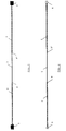
- Figure 1 draws a LEC electrosurgical loop according to the present invention.
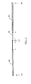
- Figure 2 depicts a first version of an LAP electrosurgical loop according to the present invention.
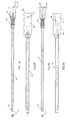
- Figures 3A and 3C represent an introducer according to an embodiment of the present invention in a top view and a side view.
- Figures 3B and 3D show a sheath according to an embodiment of the present invention in a top view and a side view.
- Figures 4A and 4C represent an introducer according to another embodiment of the present invention in a top view and a side view.
- Figures 4B and 4D show a sheath according to another embodiment of the present invention in a top view and a side view.
- Figure 5 describes a combined sheath and introducer according to the present invention.
- Figure 6 depicts a second version of an LAP electrosurgical loop according to the present invention.
- Figures 7A and 7C represent an introducer according to another embodiment of the present invention in a top view and a side view.
- Figures 7B and 7D show a sheath according to another embodiment of the present invention in a top view and a side view.
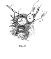
- Figure 8 shows the placement of an electrosurgical loop according to the present invention around the uterine cervix at the level of the isthmus.
- Figure 9 describes the cutting of the cervix by applying monopolar current on the electrosurgical loop according to the invention while performing lateral traction on the loop.
- Figure 10 presents a view of the cervical stump while the uterine corpus is displaced.
- the present invention concerns a new electrosurgical instrument for performing laparoscopic section of organs, in particular for performing a laparoscopic supracervical hysterectomy or a total laparoscopic hysterectomy.
- the electrosurgical instrument according to a specific embodiment of the present invention (the LEC loop) is meant to be used with the standard laparoscopic grasping forceps instrument, as described in figures 8, 9 and 10.
- Example 1 the LEC loop and insulating tube
- the LEC loop can be seen in figure 1. It comprises a continuous metal wire 1 that is covered on both ends with an insulating polymer 2 such as Teflon® or thermoretractable polyolefine (medical grade).
- the metal wire 1 is not covered in between both insulating polymer layers 2 and thus a conducting part (A-A') is freely contactable and usable for electrosurgical purposes.
- Said metal wire is preferably made of stainless steel or tungsten.
- the ends of the wire are connected to and in electrical contact with clips 3, which enable the surgeon to manipulate the LEC loop using a standard laparoscopic forceps.
- the LEC loop is used in co-operation with an insulated tube.
- Said tube is a 10 mm wide tube with a 5 mm reductor that is introduced in the non-insulated surgical trocar.
- the length of the tube should be enough for it to contain the full length LEC loop wire, thus insulating the LEC loop from the trocar.
- the forceps is then pulled back until the loop is entirely introduced in the insulating tube.
- the tube is then inserted in the peritoneal cavity trough the trocar.
- the forceps is pushed until the loop is entirely pushed out of the insulating tube into the peritoneal cavity.
- the LEC loop can then be positioned around the organ that needs to be sectioned with the help of a second forceps that can hold the second end of the LEC loop.
- the second forceps is inserted through a second trocar.
- the second end of the LEC loop is then directed to the first laparoscopic forceps and connected hereto by grasping the clip at the second end. Closing of the jaws of the forceps and retracting said forceps through the insulating tube permits to hide the freely contactable clips at the peripheral ends of the LEC loop inside the insulating tube and, when executing a lateral traction to the LEC loop while applying a high-frequency monopolar current to the LEC loop, the organ will be sectioned.
- Example 3 first version of the LAP loop:
- the LAP loop can be seen in figure 2. It comprises a continuous metal wire 1 that is covered on both ends with an insulating polymer 2 such as Teflon® or thermoretractable polyolefine (medical grade).
- the metal wire 1 is not covered in between both insulating polymer layers 2 and thus a conducting part (B-B') is freely contactable and usable for electrosurgical purposes.
- Said metal wire is preferably made of stainless steel or tungsten.
- One end of the wire is connected to and in electrical contact with a metal sphere 4, while the second end of the wire is connected to a screw 5, preferably being at least covered with an electrically insulating material such as Teflon®.
- the metal sphere 4 can be replaced by another geometrical form, which can be clamped inside a groove in the lap loop instrument adapted to retain the form. Further, the screw can be replaced by any fixation means, compatible with the lap loop instruments.
- Example 4 a first version of LAP loop instruments using the first version of the LAP loop
- FIG. 3A and 3C represent a LAP introducer instrument.
- Figures 3B and 3D represent a LAP sheath instrument.
- the LAP introducer instrument comprises an electrically insulated handle 6 connected to an insulated rod 7, comprising at its distal end a threaded hole 8 or the like adapted to fit the screw 5 or the like of the LAP loop and a groove 9 adapted to receive the sphere 4 or the like of the LAP loop. Said groove is in electrical contact with a contact 10, located at the proximal part of said rod 7. Also at the proximal part of said rod 7 near said insulated handle 6, there is an electrically insulated spring 11.
- the insulated handle comprises preferably a pin 12
- the LAP sheath instrument comprises a handle 13 comprising a second groove 14, adapted to fit pin 12, an electrical plug 15, which is in electrical contact with a contactor mechanism 16 and an opening 17 adapted to receive the introducer handle.
- the LAP sheath instrument comprises an insulating tube 18, that is adapted to receive the rod 7, but having a reduced length so that, when the introducer is pushed in to the sheath as far as possible, the distal end of the rod 7 is outside of the insulating tube 16.
- the handle 13 is adapted so that, in this introducer position, the contactor mechanism 16 can only contact the insulated spring 11 of said introducer.
- the contactor mechanism 16 When the introducer is retracted so that rod 7 is completely inside insulating tube 18, the contactor mechanism 16 is, when depressed, in contact with the contact 10 of the introducer, thus achieving electrical contact between the plug 15 of the sheath and the groove 9 of the introducer, and the wire 1 of the LAP loop when the sphere 4 is inside the groove 9.
- the contact 10 is adapted to fix the contactor mechanism 16 when this position is taken. A rotation of the introducer with regard to the sheath in this position will fix the introducer more rigidly, as the pin 12 of the introducer will end up in the side-arm of second groove 14 of the sheath, thereby excluding further translational movement of the introducer inside the sheath.
- Example 5 use of the first version of the LAP loop with first version of the LAP loop instruments
- the LAP loop can then be positioned around the organ that needs to be sectioned with the help of a forceps that can hold the second end of the LAP loop.
- the forceps is inserted through a second trocar.
- the sphere 4 of the LAP loop is then directed to the distal end of the introducer and placed into the groove 9 at said distal end. Retraction of the introducer until the distal end of the introducer is completely inside the insulating tube is followed by a rotation resulting in fixation of the pin 12 in the side-arm of second groove 14.
- the insulating tube prevents, in this position, the sphere 4 of the LAP loop to move since it is fixed in the groove 9 of the introducer, while the wire 1 of the LAP loop is in electrical contact with the plug 15 of the sheath via the contactor mechanism 16.
- the organ When executing a lateral traction to the LAP loop while applying a high-frequency monopolar current to the LAP loop, the organ will be sectioned.
- the LAP loop and LAP loop instruments provide higher safety, since a closed electrical circuit is only possible when both ends of the loop are installed and the distal end of the introducer is hidden by the insulating tube.
- Example 6 a second version of LAP loop instruments:
- FIG. 4A and 4C represent a LAP introducer instrument.
- Figures 4B and 4D represent a LAP sheath instrument.
- the LAP introducer instrument comprises an electrically insulated handle 19 connected to an insulated rod 20, comprising at its distal end a threaded hole 21 or the like adapted to fit the screw 5 or the like of the LAP loop and a groove 22 adapted to receive the sphere 4 or the like of the LAP loop. Said groove is in electrical contact with an electrical plug 23, located inside handle 19. Also, at the proximal part of said rod 20 near said insulated handle 19, there is an electrically insulated spring 24.
- the insulated handle comprises a second groove 25, adapted to fit the pin 27 of the sheath.
- the LAP sheath instrument comprises a handle 26 comprising a pin 27 and an opening 28 adapted to receive the introducer handle.
- the LAP sheath instrument comprises an insulating tube 29, that is adapted to receive the rod 20, but having a reduced length so that, when the introducer is pushed in to the sheath as far as possible, the distal end of the rod 20 is outside of the insulating tube 29, as can be seen in figure 5B.
- the introducer When the introducer is retracted so that rod 20 is completely inside insulating tube 29, the introducer can be rotated with regard to the sheath which will fix the introducer more rigidly, as the pin 27 of the sheath will end up in the side-arm of second groove 25 of the introducer, thereby excluding further translational movement of the introducer inside the sheath.
- the introducer and sheath are then in the position as can be seen in figure 5A.
- Example 7 use of the first version of the LAP loop with second version of the LAP loop instruments
- the LAP loop is screwed on the distal end of the introducer with its screw 5.
- the introducer is then retracted, which allows the distal end to enter the insulating tube 29 again.
- the introducer is then pulled back until the LAP loop is entirely introduced in the insulating tube.
- the sheath is then inserted in the peritoneal cavity through the trocar.
- the introducer is again pushed until the LAP loop is entirely pushed out of the insulating tube 29 into the peritoneal cavity until maximal insertion (insulated spring 24 compressed).
- the LAP loop can then be positioned around the organ that needs to be sectioned with the help of a forceps that can hold the second end of the LAP loop.
- the forceps is inserted through a second trocar.
- the sphere 4 of the LAP loop is then directed to the distal end of the introducer and placed into the groove 22 at said distal end. Retraction of the introducer until the distal end of the introducer is completely inside the insulating tube is followed by a rotation resulting in fixation of the pin 27 in the side-arm of second groove 25.
- the insulating tube 29 prevents, in this position, the sphere 4 of the LAP loop to move since it is fixed in the groove 22 of the introducer, while the wire 1 of the LAP loop is in electrical contact with the plug 23 of the sheath.
- the organ When executing a lateral traction to the LAP loop while applying a high-frequency monopolar current to the LAP loop, the organ will be sectioned.
- Example 8 second version of the LAP loop :
- the second version of the LAP loop can be seen in figure 6. It comprises a metal wire 41 which is not continuous but is constituted by two different conducting threads connected to a common insulating zone 43 ( of plastic for example), so that no current can occur from one part of the conducting wire to the other.
- said conducting wire is covered on both ends with an insulating polymer 42 such as Teflon® or thermoretractable polyolefine (medical grade).
- the metal wire 41 is not covered in between the two polymer layers 42 and thus two conducting parts (C-C') and (D-D') are freely contactable and usable for electrosurgical purposes.
- Said metal wire is preferabaly made of stainless steel or tungsten.
- One end of the wire is connected to and in electrical contact with a metal sphere 40, while the second end of the wire is connected to and in electrical contact with a metal screw 50.
- the metal sphere 40 can be replaced by another geometrical form, which can be clamped inside a groove in the lap loop instrument adapted to retain the form. Further, the metal screw can be replaced by any fixation means, compatible with the lap loop instruments.
- FIG. 7A and 7C represent a LAP introducer.
- Figure 7B and 7D represent a LAP sheath instrument.
- the LAP introducer instrument comprise an electrically insulated handle 59 connected to an insulated rod 60, comprising at its distal end a threaded hole 61 adapted to fit the screw 50 or the like of the second version of the LAP loop and an insulated groove 62 adapted to receive the sphere 40 or the like of the second version of the LAP loop.
- Said threaded hole 61 is in electrical contact with an electrical plug 63, located inside handle 59.
- an electrically insulated spring 64 located inside handle 59.
- the insulated handle 59 comprises a second groove 65, adapted to fit the pin 67 of the sheath.
- the LAP sheath instrument comprises a handle 66 comprising a pin 67 and an opening 66 adapted to receive the introducer handle 59.
- the LAP sheath instrument comprises a tube 69 which is insulated outwardly but is not insulated inwardly.
- Said tube 69 is adapted to receive rod 60, but has a reduced length so that, when the introducer is pushed in to the sheath as far as possible, the distal end of the rod 60 is outside of the tube 69.
- the LAP sheath which is not insulated inside, also comprises an electrical plug 70, which is in electrical contact through its not insulated interior with the sphere 40.
- the introducer When the introducer is retracted so that rod 60 is completely inside the tube 69, the introducer can be rotated with regard to the sheath which will fix the introducer more rigidly, as the pin 67 of the sheath will end up in the side-arm of second groove 65 of the introducer, thereby excluding further translational movement of the introducer inside the sheath.
- Example 10 use of the second version of the LAP loop and of the third version of the LAP loop instruments
- the second version of the LAP loop is screwed on the distal end end of the introducer with its screw 50.
- the introducer is then retracted, which allows the distal end of the introducer to enter the tube 69 again.
- the introducer is then pulled back until the LAP loop is then pulled back until the LAP loop is entirely introduced in the tube 69.
- the sheath is then inserted in the peritoneal cavity through the trocar.
- the introducer is again pushed until the LAP loop is entirely pushed out of the tube 69 into the peritoneal cavity until maximal insertion (insulated spring 24 compressed).
- the LAP loop can then be positioned around the organ that need to be sectioned with the help of a forceps that can hold the second end of the LAP loop.
- the forceps is inserted through a second trocar.
- the sphere 40 of the LAP loop is then directed to the distal end of the introducer and placed into the groove 62 at said distal end. Retraction of the introducer until the distal end of the introducer is completely inside the tube 69 is followed by a rotation resulting in fixation of the pin 67 in the side-arm of second groove 65.
- the tube 69 of the sheath prevents, in this position, the sphere 40 of the LAP loop to move since it is fixed in the groove 62 of the introducer, while the wire 41 of the LAP loop is in electrical contact from one side with the plug 63 of the introducer and from the other side with the plug 70 of the sheath.
- the organ When executing a lateral traction to the LAP loop while applying a high-frequency bipolar current to the LAP loop, the organ will be sectioned. It is also possible to retract the introducer inside the sheath while applying the high-frequency bipolar current to the LAP loop, in order to avoid a potential short-circuit.
- a plastic apparatus may be used.
- Example 11 use of the electrosurgical apparatus according to the present invention to perform a laparoscopic supracervical hysterectomy (LSH)
- LSH laparoscopic supracervical hysterectomy
- Preparation for LSH includes placement of a uterine manipulator and catheterisation of the bladder.
- the surgical approach is through the usual laparoscopic portals: a primary portal for the optic and two or three secondary portals (5 and 12 mm) for ancillary instruments.
- Treatment of the round ligaments and adnexae follows standard hysterectomy technique.
- the broad ligament and the vesicouterine fold are dissected down to the superior cervix.
- the uterine vessels Prior to applying the electrosurgical loop of the invention, the uterine vessels are dissected and sectioned after occluding them with bipolar coagulation or placement of sutures.
- the LEC loop according to the present invention is then introduced into the abdominal cavity and placed around the cervix 30 (see figure 8).
- the ends of the loop are firmly held with grasping forceps 31 to form a lasso around the cervix 30 at the level of the isthmus.
- the uterus 32 is retracted laterally by pulling on the stump of the round ligament 33 in order allow clear vision of the adjacent structures such as bladder, rectum, intestine, etc. (see figure 9).
- Sectioning of the cervix 30 is accomplished by applying high-frequency monopolar current to the electrosurgical LEC loop while it is displaced horizontally. Often it is necessary to pause the section to remove smoke and maintain good vision during amputation. After the cervix has been cut, any residual bleeding may be treated with bipolar coagulation if necessary. The result can be seen in figure 10.
- the uterine corpus is removed from the abdominal cavity by either morcellation or extraction through a culdotomy incision.
Landscapes
- Health & Medical Sciences (AREA)
- Surgery (AREA)
- Engineering & Computer Science (AREA)
- Life Sciences & Earth Sciences (AREA)
- Biomedical Technology (AREA)
- Otolaryngology (AREA)
- Nuclear Medicine, Radiotherapy & Molecular Imaging (AREA)
- Plasma & Fusion (AREA)
- Physics & Mathematics (AREA)
- Heart & Thoracic Surgery (AREA)
- Medical Informatics (AREA)
- Molecular Biology (AREA)
- Animal Behavior & Ethology (AREA)
- General Health & Medical Sciences (AREA)
- Public Health (AREA)
- Veterinary Medicine (AREA)
- Surgical Instruments (AREA)
Applications Claiming Priority (6)
| Application Number | Priority Date | Filing Date | Title |
|---|---|---|---|
| US109767 | 1980-01-07 | ||
| US10976798P | 1998-11-25 | 1998-11-25 | |
| US11230898P | 1998-12-14 | 1998-12-14 | |
| US112308 | 1998-12-14 | ||
| US240408 | 1999-01-29 | ||
| US09/240,408 US6176858B1 (en) | 1998-11-25 | 1999-01-29 | Electrosurgical loop and instrument for laparoscopic surgery |
Publications (2)
| Publication Number | Publication Date |
|---|---|
| EP1004277A1 true EP1004277A1 (fr) | 2000-05-31 |
| EP1004277B1 EP1004277B1 (fr) | 2004-07-21 |
Family
ID=27380721
Family Applications (1)
| Application Number | Title | Priority Date | Filing Date |
|---|---|---|---|
| EP99870241A Expired - Lifetime EP1004277B1 (fr) | 1998-11-25 | 1999-11-25 | Boucle électrochirurgicale et instrument pour la chirurgie laparoscopique |
Country Status (4)
| Country | Link |
|---|---|
| US (1) | US6176858B1 (fr) |
| EP (1) | EP1004277B1 (fr) |
| AT (1) | ATE271356T1 (fr) |
| DE (1) | DE69918776D1 (fr) |
Cited By (6)
| Publication number | Priority date | Publication date | Assignee | Title |
|---|---|---|---|---|
| WO2008010150A3 (fr) * | 2006-07-10 | 2008-08-14 | Lina Medical Aps | instrument électrochirurgical |
| WO2014075991A1 (fr) * | 2012-11-13 | 2014-05-22 | Trokamed Gmbh | Électrode curette |
| US9522034B2 (en) | 2014-07-22 | 2016-12-20 | Eximis Surgical, LLC | Large volume tissue reduction and removal system and method |
| US9649147B2 (en) | 2015-09-17 | 2017-05-16 | Eximis Surgical, LLC | Electrosurgical device and methods |
| US9872724B2 (en) | 2012-09-26 | 2018-01-23 | Aesculap Ag | Apparatus for tissue cutting and sealing |
| US12564392B2 (en) | 2021-08-25 | 2026-03-03 | Eximis Surgical Inc. | Containment bag |
Families Citing this family (24)
| Publication number | Priority date | Publication date | Assignee | Title |
|---|---|---|---|---|
| US6309388B1 (en) * | 1999-12-23 | 2001-10-30 | Mayo Foundation For Medical Education And Research | Symmetric conization electrocautery device |
| US6416513B1 (en) * | 2000-10-12 | 2002-07-09 | Scott Dresden | Configurable electrode instrument for use in loop electrical excision procedures |
| JP2005502423A (ja) * | 2001-07-27 | 2005-01-27 | スタリオン・インストゥルメンツ・コーポレイション | ポリープ切除用装置および方法 |
| US6616654B2 (en) | 2001-07-27 | 2003-09-09 | Starion Instruments Corporation | Polypectomy device and method |
| US6616659B1 (en) | 2001-07-27 | 2003-09-09 | Starion Instruments Corporation | Polypectomy device and method |
| US7135018B2 (en) * | 2003-09-30 | 2006-11-14 | Ethicon, Inc. | Electrosurgical instrument and method for transecting an organ |
| ES2249156B1 (es) * | 2004-07-16 | 2007-08-16 | Invenciones Medico Sanitarias, S.L. | Dispositivo oclusivo intra-deferente perfeccionado para la contracepcion masculina. |
| US7942874B2 (en) | 2005-05-12 | 2011-05-17 | Aragon Surgical, Inc. | Apparatus for tissue cauterization |
| US7803156B2 (en) | 2006-03-08 | 2010-09-28 | Aragon Surgical, Inc. | Method and apparatus for surgical electrocautery |
| US8728072B2 (en) | 2005-05-12 | 2014-05-20 | Aesculap Ag | Electrocautery method and apparatus |
| US8696662B2 (en) | 2005-05-12 | 2014-04-15 | Aesculap Ag | Electrocautery method and apparatus |
| US9339323B2 (en) | 2005-05-12 | 2016-05-17 | Aesculap Ag | Electrocautery method and apparatus |
| US8715281B2 (en) * | 2006-03-09 | 2014-05-06 | Olympus Medical Systems Corp. | Treatment device for endoscope |
| US8574229B2 (en) | 2006-05-02 | 2013-11-05 | Aesculap Ag | Surgical tool |
| EP2043542B1 (fr) * | 2006-07-06 | 2014-09-03 | Leroy L. Yates | Dispositif de résection |
| US8870867B2 (en) | 2008-02-06 | 2014-10-28 | Aesculap Ag | Articulable electrosurgical instrument with a stabilizable articulation actuator |
| ES2643464T3 (es) | 2009-06-25 | 2017-11-23 | University Of Maryland, Baltimore | Elemento electroquirúrgico y manipulador uterino para histerectomía laparoscópica total |
| KR20120139661A (ko) | 2010-02-04 | 2012-12-27 | 아에스쿨랍 아게 | 복강경 고주파 수술장치 |
| US8827992B2 (en) | 2010-03-26 | 2014-09-09 | Aesculap Ag | Impedance mediated control of power delivery for electrosurgery |
| US8419727B2 (en) | 2010-03-26 | 2013-04-16 | Aesculap Ag | Impedance mediated power delivery for electrosurgery |
| US9173698B2 (en) | 2010-09-17 | 2015-11-03 | Aesculap Ag | Electrosurgical tissue sealing augmented with a seal-enhancing composition |
| US8608738B2 (en) | 2010-12-06 | 2013-12-17 | Soulor Surgical, Inc. | Apparatus for treating a portion of a reproductive system and related methods of use |
| US9339327B2 (en) | 2011-06-28 | 2016-05-17 | Aesculap Ag | Electrosurgical tissue dissecting device |
| US20190350622A1 (en) * | 2018-05-21 | 2019-11-21 | Tarek Ahmed Nabil Abou El Kheir | Colpotomy System with Uterine Manipulator and Electrocautery for Total Laparoscopic Hysterectomy |
Citations (3)
| Publication number | Priority date | Publication date | Assignee | Title |
|---|---|---|---|---|
| EP0041719A1 (fr) * | 1980-06-10 | 1981-12-16 | Olympus Optical Co., Ltd. | Appareil chirurgical à haute fréquence du type endoscope |
| WO1993024062A1 (fr) * | 1992-05-22 | 1993-12-09 | Laparomed Corporation | Scalpel electrochirurgical a fil |
| US5814052A (en) * | 1995-06-29 | 1998-09-29 | Nakao; Naomi L. | Surgical cauterization snare with ligating suture |
Family Cites Families (9)
| Publication number | Priority date | Publication date | Assignee | Title |
|---|---|---|---|---|
| US4493320A (en) * | 1982-04-02 | 1985-01-15 | Treat Michael R | Bipolar electrocautery surgical snare |
| US5078716A (en) * | 1990-05-11 | 1992-01-07 | Doll Larry F | Electrosurgical apparatus for resecting abnormal protruding growth |
| US5158561A (en) * | 1992-03-23 | 1992-10-27 | Everest Medical Corporation | Monopolar polypectomy snare with coagulation electrode |
| US5318564A (en) * | 1992-05-01 | 1994-06-07 | Hemostatic Surgery Corporation | Bipolar surgical snare and methods of use |
| US5437665A (en) * | 1993-10-12 | 1995-08-01 | Munro; Malcolm G. | Electrosurgical loop electrode instrument for laparoscopic surgery |
| CA2156027C (fr) * | 1994-10-04 | 2006-07-18 | Keith Ratcliff | Ecarteur chirurgical |
| US5613973A (en) * | 1995-03-10 | 1997-03-25 | Wilson Greatbatch Ltd. | Laraposcopic surgical grasper having an attachable strap |
| DE19730525A1 (de) * | 1997-07-16 | 1999-01-21 | Berchtold Gmbh & Co Geb | Hochfrequenzchirurgie-Instrument |
| US9171299B1 (en) | 2014-08-07 | 2015-10-27 | International Business Machines Corporation | Isolated payment system |
-
1999
- 1999-01-29 US US09/240,408 patent/US6176858B1/en not_active Expired - Lifetime
- 1999-11-25 EP EP99870241A patent/EP1004277B1/fr not_active Expired - Lifetime
- 1999-11-25 AT AT99870241T patent/ATE271356T1/de not_active IP Right Cessation
- 1999-11-25 DE DE69918776T patent/DE69918776D1/de not_active Expired - Lifetime
Patent Citations (3)
| Publication number | Priority date | Publication date | Assignee | Title |
|---|---|---|---|---|
| EP0041719A1 (fr) * | 1980-06-10 | 1981-12-16 | Olympus Optical Co., Ltd. | Appareil chirurgical à haute fréquence du type endoscope |
| WO1993024062A1 (fr) * | 1992-05-22 | 1993-12-09 | Laparomed Corporation | Scalpel electrochirurgical a fil |
| US5814052A (en) * | 1995-06-29 | 1998-09-29 | Nakao; Naomi L. | Surgical cauterization snare with ligating suture |
Cited By (9)
| Publication number | Priority date | Publication date | Assignee | Title |
|---|---|---|---|---|
| WO2008010150A3 (fr) * | 2006-07-10 | 2008-08-14 | Lina Medical Aps | instrument électrochirurgical |
| US9872724B2 (en) | 2012-09-26 | 2018-01-23 | Aesculap Ag | Apparatus for tissue cutting and sealing |
| WO2014075991A1 (fr) * | 2012-11-13 | 2014-05-22 | Trokamed Gmbh | Électrode curette |
| US9522034B2 (en) | 2014-07-22 | 2016-12-20 | Eximis Surgical, LLC | Large volume tissue reduction and removal system and method |
| US10925665B2 (en) | 2014-07-22 | 2021-02-23 | Eximis Surgical, LLC | Large volume tissue reduction and removal system and method |
| US9649147B2 (en) | 2015-09-17 | 2017-05-16 | Eximis Surgical, LLC | Electrosurgical device and methods |
| US10603100B2 (en) | 2015-09-17 | 2020-03-31 | Eximis Surgical Inc. | Electrosurgical device and methods |
| US11648045B2 (en) | 2015-09-17 | 2023-05-16 | Eximis Surgical Inc. | Electrosurgical device and methods |
| US12564392B2 (en) | 2021-08-25 | 2026-03-03 | Eximis Surgical Inc. | Containment bag |
Also Published As
| Publication number | Publication date |
|---|---|
| EP1004277B1 (fr) | 2004-07-21 |
| ATE271356T1 (de) | 2004-08-15 |
| DE69918776D1 (de) | 2004-08-26 |
| US6176858B1 (en) | 2001-01-23 |
Similar Documents
| Publication | Publication Date | Title |
|---|---|---|
| EP1004277B1 (fr) | Boucle électrochirurgicale et instrument pour la chirurgie laparoscopique | |
| US7135018B2 (en) | Electrosurgical instrument and method for transecting an organ | |
| US5899919A (en) | Miniature endoscopic surgical instrument assembly and method of use | |
| US5891141A (en) | Bipolar electrosurgical instrument for cutting and sealing tubular tissue structures | |
| US5718703A (en) | Method and apparatus for small needle electrocautery | |
| US5445638A (en) | Bipolar coagulation and cutting forceps | |
| US6099550A (en) | Surgical instrument having jaws and an operating channel and method for use thereof | |
| US6159207A (en) | Protected ablation method and apparatus | |
| KR101283717B1 (ko) | 내시경용 처치구 | |
| US5423814A (en) | Endoscopic bipolar coagulation device | |
| US5441059A (en) | Method of minimally invasive surgery | |
| US5449355A (en) | Retrograde tissue splitter and method | |
| US5788716A (en) | Surgical instrument and method for fallopian tube ligation and biopsy | |
| US10039597B2 (en) | Surgical cutting instrument and related methods | |
| EP0589555A1 (fr) | Pince électrochirurgicale bipolaire | |
| US20100305566A1 (en) | Transcervical excision and removal of tissue | |
| US20010056283A1 (en) | Devices for investing within ligaments for retracting and reinforcing the same | |
| CN105307583B (zh) | 微创手术组件和方法 | |
| JPH1024049A (ja) | 電気外科手術用装置 | |
| JP2002503510A (ja) | 同軸の針及び切断係蹄 | |
| US20090182324A1 (en) | Laproscopic electronic surgical instruments | |
| EP1885271A2 (fr) | Procede et appareil destines a effectuer une intervention chirurgicale | |
| US20220000501A1 (en) | Passing tension member around tissue mass | |
| WO1998043548A1 (fr) | Instrument manuel a pinces | |
| KR20120065863A (ko) | 복강경 수술기구 |
Legal Events
| Date | Code | Title | Description |
|---|---|---|---|
| PUAI | Public reference made under article 153(3) epc to a published international application that has entered the european phase |
Free format text: ORIGINAL CODE: 0009012 |
|
| AK | Designated contracting states |
Kind code of ref document: A1 Designated state(s): AT BE CH CY DE DK ES FI FR GB GR IE IT LI LU MC NL PT SE |
|
| AX | Request for extension of the european patent |
Free format text: AL;LT;LV;MK;RO;SI |
|
| 17P | Request for examination filed |
Effective date: 20000927 |
|
| AKX | Designation fees paid |
Free format text: AT BE CH CY DE DK ES FI FR GB GR IE IT LI LU MC NL PT SE |
|
| GRAP | Despatch of communication of intention to grant a patent |
Free format text: ORIGINAL CODE: EPIDOSNIGR1 |
|
| GRAS | Grant fee paid |
Free format text: ORIGINAL CODE: EPIDOSNIGR3 |
|
| GRAA | (expected) grant |
Free format text: ORIGINAL CODE: 0009210 |
|
| AK | Designated contracting states |
Kind code of ref document: B1 Designated state(s): AT BE CH CY DE DK ES FI FR GB GR IE IT LI LU MC NL PT SE |
|
| PG25 | Lapsed in a contracting state [announced via postgrant information from national office to epo] |
Ref country code: NL Free format text: LAPSE BECAUSE OF FAILURE TO SUBMIT A TRANSLATION OF THE DESCRIPTION OR TO PAY THE FEE WITHIN THE PRESCRIBED TIME-LIMIT Effective date: 20040721 Ref country code: LI Free format text: LAPSE BECAUSE OF FAILURE TO SUBMIT A TRANSLATION OF THE DESCRIPTION OR TO PAY THE FEE WITHIN THE PRESCRIBED TIME-LIMIT Effective date: 20040721 Ref country code: IT Free format text: LAPSE BECAUSE OF FAILURE TO SUBMIT A TRANSLATION OF THE DESCRIPTION OR TO PAY THE FEE WITHIN THE PRESCRIBED TIME-LIMIT;WARNING: LAPSES OF ITALIAN PATENTS WITH EFFECTIVE DATE BEFORE 2007 MAY HAVE OCCURRED AT ANY TIME BEFORE 2007. THE CORRECT EFFECTIVE DATE MAY BE DIFFERENT FROM THE ONE RECORDED. Effective date: 20040721 Ref country code: FR Free format text: LAPSE BECAUSE OF FAILURE TO SUBMIT A TRANSLATION OF THE DESCRIPTION OR TO PAY THE FEE WITHIN THE PRESCRIBED TIME-LIMIT Effective date: 20040721 Ref country code: FI Free format text: LAPSE BECAUSE OF FAILURE TO SUBMIT A TRANSLATION OF THE DESCRIPTION OR TO PAY THE FEE WITHIN THE PRESCRIBED TIME-LIMIT Effective date: 20040721 Ref country code: CY Free format text: LAPSE BECAUSE OF FAILURE TO SUBMIT A TRANSLATION OF THE DESCRIPTION OR TO PAY THE FEE WITHIN THE PRESCRIBED TIME-LIMIT Effective date: 20040721 Ref country code: CH Free format text: LAPSE BECAUSE OF FAILURE TO SUBMIT A TRANSLATION OF THE DESCRIPTION OR TO PAY THE FEE WITHIN THE PRESCRIBED TIME-LIMIT Effective date: 20040721 Ref country code: BE Free format text: LAPSE BECAUSE OF FAILURE TO SUBMIT A TRANSLATION OF THE DESCRIPTION OR TO PAY THE FEE WITHIN THE PRESCRIBED TIME-LIMIT Effective date: 20040721 Ref country code: AT Free format text: LAPSE BECAUSE OF FAILURE TO SUBMIT A TRANSLATION OF THE DESCRIPTION OR TO PAY THE FEE WITHIN THE PRESCRIBED TIME-LIMIT Effective date: 20040721 |
|
| REG | Reference to a national code |
Ref country code: GB Ref legal event code: FG4D |
|
| REG | Reference to a national code |
Ref country code: CH Ref legal event code: EP |
|
| REG | Reference to a national code |
Ref country code: IE Ref legal event code: FG4D |
|
| REF | Corresponds to: |
Ref document number: 69918776 Country of ref document: DE Date of ref document: 20040826 Kind code of ref document: P |
|
| PG25 | Lapsed in a contracting state [announced via postgrant information from national office to epo] |
Ref country code: SE Free format text: LAPSE BECAUSE OF FAILURE TO SUBMIT A TRANSLATION OF THE DESCRIPTION OR TO PAY THE FEE WITHIN THE PRESCRIBED TIME-LIMIT Effective date: 20041021 Ref country code: GR Free format text: LAPSE BECAUSE OF FAILURE TO SUBMIT A TRANSLATION OF THE DESCRIPTION OR TO PAY THE FEE WITHIN THE PRESCRIBED TIME-LIMIT Effective date: 20041021 Ref country code: DK Free format text: LAPSE BECAUSE OF FAILURE TO SUBMIT A TRANSLATION OF THE DESCRIPTION OR TO PAY THE FEE WITHIN THE PRESCRIBED TIME-LIMIT Effective date: 20041021 |
|
| PG25 | Lapsed in a contracting state [announced via postgrant information from national office to epo] |
Ref country code: DE Free format text: LAPSE BECAUSE OF FAILURE TO SUBMIT A TRANSLATION OF THE DESCRIPTION OR TO PAY THE FEE WITHIN THE PRESCRIBED TIME-LIMIT Effective date: 20041022 |
|
| PG25 | Lapsed in a contracting state [announced via postgrant information from national office to epo] |
Ref country code: ES Free format text: LAPSE BECAUSE OF FAILURE TO SUBMIT A TRANSLATION OF THE DESCRIPTION OR TO PAY THE FEE WITHIN THE PRESCRIBED TIME-LIMIT Effective date: 20041101 |
|
| PG25 | Lapsed in a contracting state [announced via postgrant information from national office to epo] |
Ref country code: LU Free format text: LAPSE BECAUSE OF NON-PAYMENT OF DUE FEES Effective date: 20041125 Ref country code: IE Free format text: LAPSE BECAUSE OF NON-PAYMENT OF DUE FEES Effective date: 20041125 Ref country code: GB Free format text: LAPSE BECAUSE OF NON-PAYMENT OF DUE FEES Effective date: 20041125 |
|
| PG25 | Lapsed in a contracting state [announced via postgrant information from national office to epo] |
Ref country code: MC Free format text: LAPSE BECAUSE OF NON-PAYMENT OF DUE FEES Effective date: 20041130 |
|
| NLV1 | Nl: lapsed or annulled due to failure to fulfill the requirements of art. 29p and 29m of the patents act | ||
| REG | Reference to a national code |
Ref country code: CH Ref legal event code: PL |
|
| PLBE | No opposition filed within time limit |
Free format text: ORIGINAL CODE: 0009261 |
|
| STAA | Information on the status of an ep patent application or granted ep patent |
Free format text: STATUS: NO OPPOSITION FILED WITHIN TIME LIMIT |
|
| 26N | No opposition filed |
Effective date: 20050422 |
|
| GBPC | Gb: european patent ceased through non-payment of renewal fee |
Effective date: 20041125 |
|
| EN | Fr: translation not filed | ||
| REG | Reference to a national code |
Ref country code: IE Ref legal event code: MM4A |
|
| PG25 | Lapsed in a contracting state [announced via postgrant information from national office to epo] |
Ref country code: PT Free format text: LAPSE BECAUSE OF NON-PAYMENT OF DUE FEES Effective date: 20041221 |