EP1004376A2 - Article de mousse métallique - Google Patents
Article de mousse métallique Download PDFInfo
- Publication number
- EP1004376A2 EP1004376A2 EP19990123136 EP99123136A EP1004376A2 EP 1004376 A2 EP1004376 A2 EP 1004376A2 EP 19990123136 EP19990123136 EP 19990123136 EP 99123136 A EP99123136 A EP 99123136A EP 1004376 A2 EP1004376 A2 EP 1004376A2
- Authority
- EP
- European Patent Office
- Prior art keywords
- metal foam
- temperature control
- flow channel
- foaming
- foam material
- Prior art date
- Legal status (The legal status is an assumption and is not a legal conclusion. Google has not performed a legal analysis and makes no representation as to the accuracy of the status listed.)
- Granted
Links
- 239000006262 metallic foam Substances 0.000 title claims abstract description 122
- 239000000463 material Substances 0.000 claims abstract description 143
- 238000005187 foaming Methods 0.000 claims abstract description 114
- 239000012530 fluid Substances 0.000 claims abstract description 46
- 239000002131 composite material Substances 0.000 claims abstract description 32
- 239000000835 fiber Substances 0.000 claims abstract description 11
- 239000002657 fibrous material Substances 0.000 claims abstract description 6
- 238000004519 manufacturing process Methods 0.000 claims abstract description 5
- 239000004033 plastic Substances 0.000 claims abstract description 3
- 239000006260 foam Substances 0.000 claims description 37
- 238000010438 heat treatment Methods 0.000 claims description 27
- 238000000034 method Methods 0.000 claims description 23
- 238000005496 tempering Methods 0.000 claims description 23
- 229910052751 metal Inorganic materials 0.000 claims description 19
- 239000002184 metal Substances 0.000 claims description 19
- 210000000746 body region Anatomy 0.000 claims description 4
- 239000004744 fabric Substances 0.000 claims description 4
- 238000000465 moulding Methods 0.000 abstract description 34
- 238000004804 winding Methods 0.000 abstract description 4
- 238000010097 foam moulding Methods 0.000 abstract description 2
- 238000005304 joining Methods 0.000 description 119
- 239000010410 layer Substances 0.000 description 62
- 125000006850 spacer group Chemical group 0.000 description 43
- 239000006261 foam material Substances 0.000 description 31
- 238000001816 cooling Methods 0.000 description 16
- 230000008569 process Effects 0.000 description 14
- 239000011265 semifinished product Substances 0.000 description 14
- 239000003795 chemical substances by application Substances 0.000 description 9
- 239000011148 porous material Substances 0.000 description 9
- 238000002844 melting Methods 0.000 description 8
- 230000008018 melting Effects 0.000 description 8
- 229910052782 aluminium Inorganic materials 0.000 description 7
- XAGFODPZIPBFFR-UHFFFAOYSA-N aluminium Chemical compound [Al] XAGFODPZIPBFFR-UHFFFAOYSA-N 0.000 description 6
- 239000012809 cooling fluid Substances 0.000 description 6
- 239000007769 metal material Substances 0.000 description 6
- 229920000049 Carbon (fiber) Polymers 0.000 description 4
- 238000005452 bending Methods 0.000 description 4
- 239000004917 carbon fiber Substances 0.000 description 4
- 230000006835 compression Effects 0.000 description 4
- 238000007906 compression Methods 0.000 description 4
- 230000008878 coupling Effects 0.000 description 4
- 238000010168 coupling process Methods 0.000 description 4
- 238000005859 coupling reaction Methods 0.000 description 4
- 230000000694 effects Effects 0.000 description 4
- 238000009415 formwork Methods 0.000 description 4
- OKTJSMMVPCPJKN-UHFFFAOYSA-N Carbon Chemical compound [C] OKTJSMMVPCPJKN-UHFFFAOYSA-N 0.000 description 3
- 230000008901 benefit Effects 0.000 description 3
- 239000000919 ceramic Substances 0.000 description 3
- 238000002485 combustion reaction Methods 0.000 description 3
- 238000004049 embossing Methods 0.000 description 3
- 239000003779 heat-resistant material Substances 0.000 description 3
- 239000011261 inert gas Substances 0.000 description 3
- 239000012495 reaction gas Substances 0.000 description 3
- 238000000926 separation method Methods 0.000 description 3
- 239000007787 solid Substances 0.000 description 3
- 239000011343 solid material Substances 0.000 description 3
- 238000012546 transfer Methods 0.000 description 3
- 230000006978 adaptation Effects 0.000 description 2
- 239000000853 adhesive Substances 0.000 description 2
- 230000001070 adhesive effect Effects 0.000 description 2
- 230000015572 biosynthetic process Effects 0.000 description 2
- 230000001427 coherent effect Effects 0.000 description 2
- 238000010276 construction Methods 0.000 description 2
- 238000009792 diffusion process Methods 0.000 description 2
- 229910002804 graphite Inorganic materials 0.000 description 2
- 239000010439 graphite Substances 0.000 description 2
- 230000003993 interaction Effects 0.000 description 2
- VNWKTOKETHGBQD-UHFFFAOYSA-N methane Chemical compound C VNWKTOKETHGBQD-UHFFFAOYSA-N 0.000 description 2
- 230000001590 oxidative effect Effects 0.000 description 2
- 238000010248 power generation Methods 0.000 description 2
- 238000003825 pressing Methods 0.000 description 2
- 239000003380 propellant Substances 0.000 description 2
- 230000008439 repair process Effects 0.000 description 2
- 235000001674 Agaricus brunnescens Nutrition 0.000 description 1
- ZOKXTWBITQBERF-UHFFFAOYSA-N Molybdenum Chemical compound [Mo] ZOKXTWBITQBERF-UHFFFAOYSA-N 0.000 description 1
- 241001620634 Roger Species 0.000 description 1
- 238000004026 adhesive bonding Methods 0.000 description 1
- 238000004873 anchoring Methods 0.000 description 1
- 239000003963 antioxidant agent Substances 0.000 description 1
- 229910052799 carbon Inorganic materials 0.000 description 1
- 238000005266 casting Methods 0.000 description 1
- 230000008859 change Effects 0.000 description 1
- 238000004140 cleaning Methods 0.000 description 1
- 239000004020 conductor Substances 0.000 description 1
- 238000007796 conventional method Methods 0.000 description 1
- 239000002826 coolant Substances 0.000 description 1
- 230000007797 corrosion Effects 0.000 description 1
- 238000005260 corrosion Methods 0.000 description 1
- 238000005553 drilling Methods 0.000 description 1
- 238000007688 edging Methods 0.000 description 1
- 238000005516 engineering process Methods 0.000 description 1
- 238000001125 extrusion Methods 0.000 description 1
- 230000002349 favourable effect Effects 0.000 description 1
- 239000011521 glass Substances 0.000 description 1
- 239000003365 glass fiber Substances 0.000 description 1
- 239000012210 heat-resistant fiber Substances 0.000 description 1
- 238000000886 hydrostatic extrusion Methods 0.000 description 1
- 230000000977 initiatory effect Effects 0.000 description 1
- 230000010354 integration Effects 0.000 description 1
- 229910001338 liquidmetal Inorganic materials 0.000 description 1
- 239000011159 matrix material Substances 0.000 description 1
- 238000005259 measurement Methods 0.000 description 1
- 229910001092 metal group alloy Inorganic materials 0.000 description 1
- 239000011733 molybdenum Substances 0.000 description 1
- 229910052750 molybdenum Inorganic materials 0.000 description 1
- 239000007800 oxidant agent Substances 0.000 description 1
- 230000003647 oxidation Effects 0.000 description 1
- 238000007254 oxidation reaction Methods 0.000 description 1
- 230000002093 peripheral effect Effects 0.000 description 1
- 238000004080 punching Methods 0.000 description 1
- 230000002787 reinforcement Effects 0.000 description 1
- 230000003716 rejuvenation Effects 0.000 description 1
- 238000010079 rubber tapping Methods 0.000 description 1
- 230000035939 shock Effects 0.000 description 1
- 239000002356 single layer Substances 0.000 description 1
- 238000005245 sintering Methods 0.000 description 1
- 238000005476 soldering Methods 0.000 description 1
- 239000007858 starting material Substances 0.000 description 1
- 238000005482 strain hardening Methods 0.000 description 1
- 238000012549 training Methods 0.000 description 1
- WFKWXMTUELFFGS-UHFFFAOYSA-N tungsten Chemical compound [W] WFKWXMTUELFFGS-UHFFFAOYSA-N 0.000 description 1
- 229910052721 tungsten Inorganic materials 0.000 description 1
- 239000010937 tungsten Substances 0.000 description 1
Images



Classifications
-
- B—PERFORMING OPERATIONS; TRANSPORTING
- B22—CASTING; POWDER METALLURGY
- B22F—WORKING METALLIC POWDER; MANUFACTURE OF ARTICLES FROM METALLIC POWDER; MAKING METALLIC POWDER; APPARATUS OR DEVICES SPECIALLY ADAPTED FOR METALLIC POWDER
- B22F5/00—Manufacture of workpieces or articles from metallic powder characterised by the special shape of the product
- B22F5/10—Manufacture of workpieces or articles from metallic powder characterised by the special shape of the product of articles with cavities or holes, not otherwise provided for in the preceding subgroups
-
- B—PERFORMING OPERATIONS; TRANSPORTING
- B22—CASTING; POWDER METALLURGY
- B22F—WORKING METALLIC POWDER; MANUFACTURE OF ARTICLES FROM METALLIC POWDER; MAKING METALLIC POWDER; APPARATUS OR DEVICES SPECIALLY ADAPTED FOR METALLIC POWDER
- B22F3/00—Manufacture of workpieces or articles from metallic powder characterised by the manner of compacting or sintering; Apparatus specially adapted therefor ; Presses and furnaces
- B22F3/10—Sintering only
- B22F3/11—Making porous workpieces or articles
- B22F3/1103—Making porous workpieces or articles with particular physical characteristics
- B22F3/1118—Making porous workpieces or articles with particular physical characteristics comprising internal reinforcements
-
- B—PERFORMING OPERATIONS; TRANSPORTING
- B22—CASTING; POWDER METALLURGY
- B22F—WORKING METALLIC POWDER; MANUFACTURE OF ARTICLES FROM METALLIC POWDER; MAKING METALLIC POWDER; APPARATUS OR DEVICES SPECIALLY ADAPTED FOR METALLIC POWDER
- B22F3/00—Manufacture of workpieces or articles from metallic powder characterised by the manner of compacting or sintering; Apparatus specially adapted therefor ; Presses and furnaces
- B22F3/10—Sintering only
- B22F3/11—Making porous workpieces or articles
- B22F3/1121—Making porous workpieces or articles by using decomposable, meltable or sublimatable fillers
- B22F3/1125—Making porous workpieces or articles by using decomposable, meltable or sublimatable fillers involving a foaming process
-
- B—PERFORMING OPERATIONS; TRANSPORTING
- B22—CASTING; POWDER METALLURGY
- B22F—WORKING METALLIC POWDER; MANUFACTURE OF ARTICLES FROM METALLIC POWDER; MAKING METALLIC POWDER; APPARATUS OR DEVICES SPECIALLY ADAPTED FOR METALLIC POWDER
- B22F7/00—Manufacture of composite layers, workpieces, or articles, comprising metallic powder, by sintering the powder, with or without compacting wherein at least one part is obtained by sintering or compression
- B22F7/002—Manufacture of composite layers, workpieces, or articles, comprising metallic powder, by sintering the powder, with or without compacting wherein at least one part is obtained by sintering or compression of porous nature
- B22F7/004—Manufacture of composite layers, workpieces, or articles, comprising metallic powder, by sintering the powder, with or without compacting wherein at least one part is obtained by sintering or compression of porous nature comprising at least one non-porous part
- B22F7/006—Manufacture of composite layers, workpieces, or articles, comprising metallic powder, by sintering the powder, with or without compacting wherein at least one part is obtained by sintering or compression of porous nature comprising at least one non-porous part the porous part being obtained by foaming
-
- F—MECHANICAL ENGINEERING; LIGHTING; HEATING; WEAPONS; BLASTING
- F16—ENGINEERING ELEMENTS AND UNITS; GENERAL MEASURES FOR PRODUCING AND MAINTAINING EFFECTIVE FUNCTIONING OF MACHINES OR INSTALLATIONS; THERMAL INSULATION IN GENERAL
- F16B—DEVICES FOR FASTENING OR SECURING CONSTRUCTIONAL ELEMENTS OR MACHINE PARTS TOGETHER, e.g. NAILS, BOLTS, CIRCLIPS, CLAMPS, CLIPS OR WEDGES; JOINTS OR JOINTING
- F16B3/00—Key-type connections; Keys
- F16B3/005—Key-type connections; Keys the key being formed by solidification of injected material
-
- B—PERFORMING OPERATIONS; TRANSPORTING
- B22—CASTING; POWDER METALLURGY
- B22F—WORKING METALLIC POWDER; MANUFACTURE OF ARTICLES FROM METALLIC POWDER; MAKING METALLIC POWDER; APPARATUS OR DEVICES SPECIALLY ADAPTED FOR METALLIC POWDER
- B22F5/00—Manufacture of workpieces or articles from metallic powder characterised by the special shape of the product
- B22F2005/004—Article comprising helical form elements
-
- B—PERFORMING OPERATIONS; TRANSPORTING
- B22—CASTING; POWDER METALLURGY
- B22F—WORKING METALLIC POWDER; MANUFACTURE OF ARTICLES FROM METALLIC POWDER; MAKING METALLIC POWDER; APPARATUS OR DEVICES SPECIALLY ADAPTED FOR METALLIC POWDER
- B22F2999/00—Aspects linked to processes or compositions used in powder metallurgy
-
- Y—GENERAL TAGGING OF NEW TECHNOLOGICAL DEVELOPMENTS; GENERAL TAGGING OF CROSS-SECTIONAL TECHNOLOGIES SPANNING OVER SEVERAL SECTIONS OF THE IPC; TECHNICAL SUBJECTS COVERED BY FORMER USPC CROSS-REFERENCE ART COLLECTIONS [XRACs] AND DIGESTS
- Y10—TECHNICAL SUBJECTS COVERED BY FORMER USPC
- Y10T—TECHNICAL SUBJECTS COVERED BY FORMER US CLASSIFICATION
- Y10T428/00—Stock material or miscellaneous articles
- Y10T428/12—All metal or with adjacent metals
- Y10T428/12479—Porous [e.g., foamed, spongy, cracked, etc.]
-
- Y—GENERAL TAGGING OF NEW TECHNOLOGICAL DEVELOPMENTS; GENERAL TAGGING OF CROSS-SECTIONAL TECHNOLOGIES SPANNING OVER SEVERAL SECTIONS OF THE IPC; TECHNICAL SUBJECTS COVERED BY FORMER USPC CROSS-REFERENCE ART COLLECTIONS [XRACs] AND DIGESTS
- Y10—TECHNICAL SUBJECTS COVERED BY FORMER USPC
- Y10T—TECHNICAL SUBJECTS COVERED BY FORMER US CLASSIFICATION
- Y10T428/00—Stock material or miscellaneous articles
- Y10T428/249921—Web or sheet containing structurally defined element or component
- Y10T428/249953—Composite having voids in a component [e.g., porous, cellular, etc.]
- Y10T428/249971—Preformed hollow element-containing
Definitions
- the invention relates to metal foam moldings and a method in which a Metal foam material of a molded body in the course of the manufacture of the Molded body is foamed.
- One way to save weight is to use molded articles foamed metal foam material or proportions of such materials the pore structure of the foamed metal foam has a Metal foam molded body is lighter than a solid material manufactured molded body with still high mechanical strength.
- metal foam material has a number of other advantageous properties, such as high shock absorbency, as well as one versus the full Material reduced thermal conductivity and electrical conductivity.
- the foamed material should have as uniform a foam or pore structure as possible.
- Metal foam materials and semi-finished products and moldings made from them are for example from DE 41 01 630 C2, DE 43 18 540 AI, DE 44 16 371 Al, DE 44 26 627 Al, DE 196 12 781 01 C 1 and DE 197 17 894 Al.
- DE 43 18 540 Al describes the use of metal foam material in Motor vehicle construction proposed. Body panels are called Metal foam molded body with a fully metallic top layer and one foamed metal foam layer used. For attaching attachments to these body panels are tapping screws and dowel-like Fasteners mentioned.
- DE 196 12 781 C 1 also relates to moldings for Vehicles. In the volume “Metal Foams 1997", MIT Bremen, the article "Joining of Aluminum Foams" by N. Sedliakova et al.
- connection methods for Metal foam molded body screw connections, soldering, adhesive and Welded joints as well as the use of foamed Fasteners described. These are the ones for connecting shaped bodies Processes that have been tried and tested in technology with their well-known names and Disadvantages.
- the object of the invention is to provide a metal foam molded body with one for the Purpose of the molded body favorable structure of the foamed To create metal foam material.
- the Shaped body is a very uniform pore structure of the foam material wanted.
- the invention relates to a molded body with foamed metal foam material, which is called in the following because of this property metal foam molded body.
- the foam material can be a shaped body designed as a hollow body fill out completely.
- the foam material can also be used only in one or more shaped body regions be arranged and fill in cavities or just a structural part of the Reinforce molded body or connect structural parts.
- the metal foam material is foamed from the inside tempered.
- a temperature control agent is passed through the metal foam material.
- the Temperature control agent can be arranged so that it is only with the foaming foaming material comes into direct contact.
- the tempering agent can also be in direct contact with metal foam material before foaming stand to initiate the foaming of this material, for example. It can support the foaming or only make it possible if for example, a heat input to the location of the temperature control due to not low thermal conductivity of the foam material or only for foaming is insufficiently possible. It can also be used only or in addition to heating as a coolant serve.
- the temperature control means is preferably a flow channel to the Passing through or even for introducing a temperature control fluid through or into the Area of the molded body in which the metal foam material is located.
- the In principle, temperature control means can also be formed by another means are, for example an electrically conductive wire of a resistance heater, if only internal heating is to be carried out when foaming.
- Means a flow channel can advantageously within the structure of the Metal foam material can be either heated or cooled. With such a The metal foam material is heated or heated when it is foamed cooled to stop foaming or afterwards. Also a combination of two or all three tempering measures can be used. Particularly advantageous the entire foaming process is controlled at a controlled temperature.
- the foam material is heated from the inside for foaming, if necessary using a Internal temperature control in comparison to heating from the outside very precisely and temperature evenly adjustable in the foam material and to Solidify chilled.
- the internal temperature control enables a particularly targeted temperature control of a local one Area in which metal foam material is arranged. It becomes areas achieved in which due to the shape of the molded body and the arranged there Metal foam quantities could form cold spots or heat nests, if only from is heated or cooled outside. It can even be in the immediate vicinity be heated and cooled at the same time. There can be areas from excessive Heat input are protected. It can be heated from the inside and cooled from the outside and vice versa. It can therefore be the choice of materials for the Foaming dimensionally stable structural parts can be enlarged. It can even Different foam materials can be combined by using one material low foaming temperature due to the internal temperature control in front of too large Heat of an adjacent material with a higher foaming temperature is protected.
- any molded article can be foamed.
- Such moldings can be made as a whole in a single heating cycle be completely or partially foamed.
- a molded body foamed according to the invention with metal foam is distinguished characterized in that a temperature control means, preferably at least one flow channel for a temperature control fluid through which the foam structure is led.
- a temperature control means preferably at least one flow channel for a temperature control fluid through which the foam structure is led.
- tempering fluid is passed through in countercurrent. For this you can two flow channels closely spaced or in direct thermal contact run side by side, through which temperature control fluid is directed in opposite directions.
- Temperature fluid with the desired temperature is placed in both flow channels initiated and passed in countercurrent. Along the flow channel pair the tempering temperature is particularly even. Instead of through A thermally fluid can flow through the two Flow channels are passed through one after the other. In both flow channels one of the two flow channels can surround the other.
- Flow channel pairs can be arranged. Combinations of Flow channel pairs and individual flow channels are formed.
- nested flow channels After one particularly preferred embodiment of nested flow channels is a outer flow channel, in which an inner flow channel is received one end, which can lie in the foam material, closed.
- the hot tempering fluid is introduced into the inner flow channel and flows through the inner flow channel and emerges from the inner flow channel at the closed end of the outer flow channel into the outer flow channel on. Then it flows in the space between the inner and the outer flow channel back to a temperature control device. It takes place here Heat balance between the temperature control fluid in the inner flow channel and the back flowing temperature fluid instead of a particularly uniform temperature of the temperature fluid flowing back over the entire length of the flow channel causes.
- the inner flow channel is preferably preferred over its entire length centered, spaced from the outer flow channel. Serve for this arranged between the inner flow channel and the outer flow channel Spacers.
- the spacers are made of a heat-resistant material, for example made of ceramic.
- the flow of the external temperature control fluid is preferably turbulent.
- the heat conduction from the inner flow channel into the externally flowing tempering fluid and from the externally flowing tempering fluid to the Foam material increased compared to a laminar flow.
- the spacers can be designed to generate turbulence.
- the turbulent external flow is preferably brought about by means of a band which is spirally wrapped around the inner temperature control channel.
- such a tape also serves as a spacer, i.e. it is beyond no further spacers required.
- the tape is knitted Band formed, in particular from heat-resistant fibers such as Glass fibers, Ceramic fibers or carbon fibers.
- the flow channels are formed by tubes, then these tubes are located at the temperatures of the foaming, for example 500 to 800 ° C in the case of Al foam material, above the softening temperature of a whole range of metallic materials, which in the case of aluminum is around 180 ° C. If aluminum is used as the material for the flow channel, then the Foaming temperature of aluminum foam also close to or already above Solidus temperature of aluminum of around 660 ° C. It consists in Metal foam area because of the foaming material in it, the risk of that the flow channel or channels are compressed.
- the flow channel or the plurality of flow channels are preferably made of a heat-resistant one Material made, preferably of glass, ceramic, carbon and / or others heat-resistant materials, especially fiber materials.
- the thermal conductivity of the particularly heat-resistant material acted in the material of the flow channels fibers of another material that has a solidus temperature that is significantly higher than the solidus temperature of the metal foam material used.
- the metal foam material used In the case of Al foam it is this knitted thermal fibers preferably around graphite fibers, molybdenum fibers and / or tungsten fibers.
- the melting temperatures of these materials are clear above 2000 ° C and the thermal conductivity at 20 ° C is at least 130 W / mK.
- thermo fiber material it can also be used as a thermal fiber material other materials with a sufficiently high melting temperature and one sufficiently good thermal conductivity, especially with a melting temperature of above 2000 ° C and a thermal conductivity of at least 130 W / mK become. If a heat and pressure resistant material, which at the same time has good thermal conductivity and with the material to be foamed is compatible, the flow channel or the multiple flow channels can also be made entirely from such a material. Graphite enters for this Example from.
- a temperature control device preferably has an internal combustion engine Turbocharger.
- the exhaust air is used as the heating fluid.
- the cooling fluid is the Supply air used to the loader.
- the driving force of the engine can Power generation can be used.
- the temperature control agent can be used for repairs to prevent heat in the foamed molded body to reduce to a safe level. This is particularly advantageous for repairs after a preferred joining foam.
- the tempering agent also forms a mechanical reinforcement of the foamed Shaped body and is advantageously also in an optimal in this regard Arranged way. This also creates a fiber composite body, with a Temperature control forms a fiber.
- the flow channel can be perforated to the temperature control directly with the To bring foam material into contact.
- the metal foam material is from the inside acted upon with a fluid, preferably an inert gas or reaction gas through which the oxidative effect of one contained in the foamable metal foam material Propellant is reduced or strengthened.
- a fluid preferably an inert gas or reaction gas
- perforated flow channel can preferably be through the aforementioned Temperature control channel are formed; however, there can be a separate additional channel, which has small openings, i.e. a perforated channel. in the In the case of flow channels lying one inside the other, the outer one would of course be Provide a flow channel with a perforation.
- the temperature control fluid and the fluid for controlling an oxidation can by the same fluid are formed.
- a preferred shaped body is made of a plate-shaped layer material manufactured, the at least one layer of a foamable metal foam material and an adjacent top layer of a metallurgically compatible one Has full metal material.
- Such semi-finished products are known by Deformation process, in particular cold forming, a shaped body in the sense of Invention made.
- the foam and the solid material each formed by the same metal or the same metallic alloy, for example, expandable aluminum foam and all-aluminum.
- Each compatible unequal material pairing is however for the purposes of the invention can also be used, preferably the foaming temperature of the Foam material is below the melting temperature of the solid material.
- the Foam material of one or more moldings can also be made before Connect to be foamed.
- One or more of the moldings to be connected can also consist only of metal foam material.
- the invention is not for application to moldings which Metal foam materials contain limited, but also with advantage metallic moldings without foam material, for example in conventional Sheets and other profile or shell bodies, can be used. It can for example, a molded body obtained by sintering or casting act.
- the invention is, although preferred, not limited to metallic moldings limited.
- the internal temperature control according to the invention any type of molded body is foamed, as long as these moldings at the foaming temperature of the one used Foam material will not be destroyed; preferably you should at the Foaming temperature remains dimensionally stable.
- the invention creates in this regard, however, additional freedom with regard to the choice of materials.
- the temperature control means is preferably at least one temperature control fabric connected, which increases the outer surface of the temperature control.
- the Tempering fabrics protrude from the tempering agent into the foam material. There should be one between the temperature control sheet and the temperature control medium there is as good a thermal connection as possible.
- These additional temperature control surfaces of the tempering surface structure act like cooling and / or heating fins.
- additional temperature control surfaces are used as structured sheet metal structures executed.
- flat sheets with a pocket or - Cup structure for example by embossing.
- additional tempering surfaces zigzag bent sheet metal strips used.
- both embodiments have two surfaces converging in an edge or their respective imaginary Extensions together at an angle as described above.
- the single bag has a size that is one third to two thirds of that expected average size of a single foam bubble or pore corresponds.
- the volume of the individual pocket is half that expected average volume of a foam bubble or pore.
- a temperature control channel is preferably in the by means of spacers molded body to be foamed is held in the desired position.
- a spacer forms an additional temperature control surface.
- the internal temperature control is advantageously used in a joining process in which Shaped body using a metal foam material to form a solid composite body be pressed.
- the moldings to be connected are made in a first
- the step is fixed relative to each other in the position desired for the composite they are preferably clamped together.
- In their joining area means a joint, a space, in particular a cavity, limited and thereby switch, in which foamable metal foam material is arranged.
- the Metal foam material can be used before joining, during or after Joining clips must be inserted into the space switched by the joining clip.
- the foamable metal foam material is foamed, which is preferably done by heating to the foaming temperature of the Metal foam material is made. Because of the foaming Volume increase of the metal foam material and its limitation by the the molded bodies become sufficiently solid formwork to form a composite body pressed.
- the joining clamp itself is used as a shaped body in the sense of the invention Roger that.
- a pre-fabricated clip is used separate joining clamp used.
- This separate joining clamp is attached to the connecting molded body, which is preferably previously in the form of later composite have been arranged to match each other by the Molded body or at least parts of the molded body.
- the Joining clamp, the molded body to be connected is already clamped in its for the Fix the desired relative position to each other. A non-jamming one Attaching the joining clamp is also possible.
- the joining clamp is passed through appropriate training of the molded body to be formed, so that the Attachment of a separate connecting part can be omitted.
- the joining bracket is in In this case, an integral part of one of the moldings or is in Interaction of the molded body formed.
- foam material can be related to the foaming process and the later foamed molded body in an optimized The amount and shape are introduced into the frothing area. If the molded body does not itself contain any foamable metal foam materials in the foam area, foam material is delivered in this way at least through a supplementary profile.
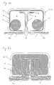
- Fig. 1a shows a joining area of a first molded body 1 and a second Shaped body 2 in a cross section.
- Shaped bodies 1 and 2 are preformed segments for later use, for example Body panels of a motor vehicle or hull segments of a ship or Aircraft.
- a plate-shaped Semi-finished product consisting of a foamable layer 4 used Metal foam material sandwiched between a lower and an upper one fully metallic top layer 3 and 5 is arranged
- the layer composite in the semi-finished product for the moldings 1 and 2 can, for example, by means of adhesive or Diffusion liability should be established.
- Such a semi-finished product becomes Carrying out a separation process the shaped bodies 1 and 2 by cold working receive.
- connection profile 6 formed by double edging.
- Such a connection profile 6 in the form of a flanged edge has one of the respective molded body 1 or 2 protruding first web 7 and an adjoining, again to the same Shaped body folded over second web 8.
- the second web 8 runs in Embodiment spaced parallel to the underlying end portion of the respective molded body 1 or 2.
- the joining clamp 10 is formed by a hollow cylindrical profile with a circular cross section 11 formed, which in its longitudinal direction from the straight, from one end to other end face through opening 12 is broken.
- the joining clamp 10 is also made from a plate-shaped metal foam semi-finished product. Therefor the semi-finished product is cut rectangular and into the hollow cylindrical Profile shape cold worked, for example bent or rolled. It would be the same Manufacture from a hollow cylindrical semi-finished product by removing the Longitudinal opening 12 possible.
- the semi-finished product of the joining clamp 10 is also around layer material, in the exemplary embodiment of FIG two-layer material, with a foamable layer 15 one Metal foam material and a fully metallic cover layer 14 from the same Metal. A bond between the two layers 14 and 15 can for example be produced by gluing or diffusion adhesion. Forms in the hollow cylinder profile 11 the foamable layer 15 enveloped by the outer cover layer 14 Inner layer.
- the joining clamp 10 encompasses the two abutting ones Connection profiles 6. Both of your longitudinal edges delimiting the opening 12 come to lie on both sides of the connection profiles 6 in the region of the first webs 7. Between First webs 7 and the longitudinal edges of the joining bracket 10 remain a gap. The second webs 8 pointing away from one another come in the region of the largest Cross-sectional extent of the hollow cylinder profile 11 to lie. The joining clamp 10 is pushed lengthways onto the connection profiles 6, since it itself is not deformable.
- the joining clamp 10 is held in the position shown in which it joins the joining area with the two connection profiles 6 like a shell. It will be in Embodiment by holding means in the position shown to the moldings 1 and 2 held.
- the joining clamp 10 can, however, in principle also be used with a low elasticity so that they are already shown in the Starting position of the moldings 1 and 2 these two moldings in this Starting position clamped and fixed, in particular by the webs 7th presses against each other in the area of the opening 12 of the joining clamp 10.
- It would be correspondingly coordinated shape of the molded body 1 and 2 and Joining clip 10 also possible, the joining clip 10 before foaming on the Shaped bodies 1 and 2 or their connecting profiles 6 seated in the for To hold the desired position in a positive manner. In any case, it has one sufficient rigidity, so that they can be foamed later of metal foam material the formwork function and the associated Can have a bracket function.
- the hollow cylinder profile 11 After or before the joining clamp 10 is placed in a space 9, the is switched over by the hollow cylinder profile 11, in particular the cover layer 14, Supplementary profiles 17 inserted from a foamable metal foam material.
- the Supplementary profiles 17 are used to adjust the amount of foam material and later resulting density of the foamed foam material within that of the Hollow cylinder profile 11 limited space 9.
- FIG. 2a shows a second embodiment of a joining clip 10.
- this joining clip 10 sets longitudinally on both sides of the opening 12 of the Joining hollow profile 11 each a support profile 13.
- Such a support profile 13 can for example, by bending in the course of forming the hollow cylinder profile 11 are molded. With its free longitudinal edge, such a support profile 13 sits in the applied state of the joining clamp 10 on one of the shaped bodies 1 and 2. At horizontal alignment, no additional bracket is required for this Joining bracket 10.
- Each of the support profiles 13 forms a cross strut between the respective molded body 1 and 2 and that of the molded body Connection profile 6.
- the support profiles 13 additionally stiffen the molded body composite.
- the support profiles 13 are plate-shaped by the same Semi-finished products such as the hollow cylinder profile 11 could, however, in principle also be made from another semi-finished product made of compatible material. Even with the Support profiles 13 is an inner, foamable layer 15 ' Metal foam material from an outer cover layer 14 'of a fully metallic Material covered. Each support profile 13 limited by its strut-shaped Arrangement of the inner edge space in the foot area of the respective connection profile 6. Since the foamable material of the layer 15 'is present in this inner edge space this space is also foamed during subsequent foaming and thereby the bond further stiffened.
- the arrangement of Fig. 1 b corresponds completely to that of Fig. 1a, so that the above explanations in connection with the arrangement according to FIG. 1 b.
- Fig. 1b and Fig. 2b show the respective after foaming the Pressed composite of the two molded bodies according to the metal foam material 1a and 2a and the joining bracket 10 for the previously described Joining clamp connections.
- the joining clamp 10 namely the cover layer 14, together with the connection areas of the Shaped body 1 and 2, but essentially the joining bracket 10 alone, a Formwork for the foaming and finally the foamed Metal foam material in room 9 and in the inner edge area of the connection profile 6 of the second molded body 2 form. In doing so, the foamed and refilled cooled metal foam material from both rooms evenly.
- connection profiles 6 as simply upstanding webs 7 to train. Even then, the two moldings 1 and 2 with each other abutting end faces of their respective connection profiles 6 pressed firmly against each other and already connected through it. Furthermore, after foaming in Inside the casing, a coherent, homogeneous metal foam structure emerged from the metal foam material of the first molded body 1 over the Metal foam material in the hollow cylinder profile 11 of the joining bracket 10, which is a bridge forms, enough for the metal foam material of the second molded body 2. To increase the strength of this bond, which is already a combined force and Composite forms, still contributes to the shape of the connection profiles 6, the act as anchoring due to their shape. In the matrix of the foamed Metal foam material within the hollow joint profile 11 are the shaped bodies 1 and 2 due to the formation of the second webs 8 mushroom-shaped or anchored barb-like.
- 3a and 4a show the joining area of two molded bodies 1 and 2, each differently thick fully metallic cover layers and one in between Have layer of a foamable metal foam material, such as the moldings of the embodiment of FIGS. 1a and 2a.
- the joining bracket 10 of the 3a and 4a is by a hollow cylinder profile 11 in a simple rectangular cross-sectional shape with the continuous longitudinal opening 12 is formed. While the joining clip 10 of the embodiment of FIG. 3a in two to be pointed towards each other, forming the longitudinal opening 12 between them Longitudinal legs 13a runs out, are the two in the joining bracket 10 of Fig. 4a Leg 13a bent into the interior 9 of the hollow cylindrical profile 11 and extend in this way a distance parallel to the web 7 of the facing connection profile 6.
- the Joining clamp 10 with the two forming the longitudinal opening 12 between them Rectangular legs 13a on the shaped bodies 1 and 2.
- the joining clip 10 will when foaming with their legs 13a firmly against the opposite Surfaces of the molded body 1 and 2 pressed.
- the composite body is additionally stiffened.
- Fig. 4a is the additional inwardly bent leg 13b an even stiffer connection of the molded body through the joining clip than in the embodiment 3a. If required, the moldings 1 and 2 for the joining process are additionally from fixed outside.
- 3b and 4b show the rectangular joining clips 10 described above after foaming.
- the joining bracket 10 and the two Shaped bodies 1 and 2 enclosed space 9, evenly and completely with the foamed metal foam filled.
- This is similar to the previous ones described embodiments a fixed connection of the two moldings 1 and 2 through positive and positive locking.
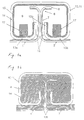
- FIG. 5a and 5b show an embodiment of a molded body composite before and after foaming, in which both the moldings 1 and 2 and the Joining clip 10 formed by already foamed metal foam molded body become.
- profiles made from plate-shaped semi-finished products are manufactured.
- the starting material for profiles 1, 2 and 10 is a three-layer Semi-finished product, in which the middle, foamed metal foam layer 4 through on both sides a fully metallic cover layer 3 and 5 is covered.
- the moldings 1 and 2 and the joining clamp 10 experience when foaming for the purpose of connecting the Shaped body 1 and 2 no further change in volume or shape.
- the joining clamp 10 can also initially be shaped as a hollow profile and in whole or in part inserted supplementary profiles are foamed instead of from a Form sheet material with a foamed layer.
- connection profiles 6 of this embodiment are made by folding once or bending parallel to each of the longitudinal edges of each of the shaped bodies 1 and 2.
- the longitudinal edges of the shaped bodies are bent through more than 90 degrees and as a result bent back to the respective molded body, creating a V-shaped Inner edge area is created.
- the Joining bracket 10 on a hollow cylinder profile 11, as it is from a rectangular Plate material can be obtained when two are facing each other Long edges to be folded towards each other. This creates a cross-section hollow cylindrical triangular shape, the triangle at one tip to form a Longitudinal opening is cut off or open.
- connection profiles 6 or the joining bracket 10 corresponding to plate-shaped, triangular Spacers 19 used in the longitudinal direction of the composite from each other spaced like wedges between the facing surfaces of the Connection profiles 6 sit. It is created by the two of each other opposite, mutually facing legs of the joining bracket 10 held together, perfectly defined crosswise to the longitudinal direction.
- the material of the spacers 19 is chosen so that its melting temperature sufficiently above the foaming temperature of the to produce the composite metal foam material to be foamed.
- the spacers 19 can for example made of the same material as the all-metal cover layers of the Shaped body 1 and 2 or the joining bracket 10 exist.
- a foamable Metal foam material is limited in the formwork formed in this way Room 9 only the material of supplementary profiles 17 available.
- the Spacers can be formed from wire or sheet metal.
- the switched room 9 is arranged from the inside by means of a room 9 Temperature control means 18 tempered.
- the temperature control means 18 is by a continuous flow channel formed through the one for the purpose of Heating for foaming a heating fluid or another cooling fluid for the purpose of cooling at the end of foaming and also afterwards. If you want to heat as well as cool later, it may be useful a separate flow channel in the manner of channel 18 for each of these purposes to provide.
- the channel 18 or a separate own channel can be introduced an inert gas or a reaction gas with which the Metal foam material is applied when foaming to have oxidative effects of a propellant contained therein to reduce or amplify.
- an inert gas or a reaction gas with which the Metal foam material is applied when foaming to have oxidative effects of a propellant contained therein to reduce or amplify can also be a heating and / or cooling fluid form. So that the inert or reaction gas comes into contact with the metal foam and responds is a channel with my openings intended for this purpose, a so-called perforation.
- foamable Supplementary profiles 17 via a through the flow or temperature control channel 18th flowing temperature control fluid can be ensured particularly safely that the foamed profiles 1, 2 and 10 of the foamed foam before joining are not influenced, e.g. by undesirably initiating a new one Foaming profiles 1, 2 and 10.
- the channel 18 can be made from a tube with any Cross-sectional shape can be formed, wherein the tube consists of a material which has a sufficiently higher melting temperature than that required for foaming Temperature of the bath fluid.
- the supplementary profiles 17 are provided with a bore, which in shape and Size is the same as the pipe cross section.
- the supplementary profiles 17 can be on the channel 18 alternately threaded with the spacers 19 and in the Cavity 9 are introduced.
- the spacers 19 are shaped so that they Channel 18 with the threaded supplementary profiles 17 centered in the cavity 9 hold.
- the spacers 19 simultaneously form radially projecting cooling fins and / or heating fins of the temperature control channel 18. They are used in particular for heating of the supplementary profiles 17. After foaming, yours will be compared to the Metal foam significantly higher thermal conductivity used to the foam phase in Cool room 9 quickly and specifically.
- room 9 there can be several temperature control channels 18, at least one channel for each the stated purposes or several for each of the stated purposes his.
- the foamable metal foam material is immediately surrounding the channel 18 arranged. This makes it possible to use temperature control agents and metal foam material to integrate a work step in the joining area. It is also possible to Commercially available extruded profiles made from non-foamed metal foam material pierce and thread on the temperature control channel 18.
- the supplementary profiles 17 should sit firmly on the temperature control channel to ensure good heat transfer guarantee. If spacers 19 are arranged along the temperature control channel 18 are, the individual supplementary profiles 17 each between such Spacers 19 to be threaded.
- a temperature control channel 18 can be through a one-piece tube are formed, on which the spacers 19 are pushed and so that they are preferably connected with good thermal conductivity. In doing so Supplementary profiles 17 each threaded between the spacers 19.
- Such a Temperature control channel 18 can also be pieced together in sections, for example by pressing abutting duct pieces into one Connecting sleeve.
- One temperature control channel or several temperature control channels and spacers, such as described above, can also in the cavities of the joining bracket 10 Embodiments can be provided according to Figures 1a to 4b.
- FIG. 5b shows the molded body composite after foaming.
- the channel 18 is also the replacement of a damaged molded body or a damaged one Shaped body area possible in a very simple manner, since with the help of the channel 18 only local heating in the joining area of the exchange molded body can be. If, for example, the damaged area of a molded body becomes visible a replacement molded part is replaced, the damaged molded part is removed separated the composite. The channel 18 is formed on the thereby Separation points of the molded body also severed. The channel pieces in the remaining Composite bodies are connected with a cooling device. The channel piece in the The area of the part of the molded body that is separated out is removed using a heating device connected and as a temperature control channel for joining foams for the exchange molded body used.
- a new temperature control channel in the joining area for the Exchange moldings are arranged.
- the Heating device a heating fluid to the temperature control channel for the exchange molded body directed to the heater after flow.
- the temperature control channel for the exchange molded body is formed Connector in the circuit of a heating fluid.
- the remaining temperature control channels 18 of the shaped body regions serve for heat input adjoin the exchange molded body as connecting channels in one Cooling circuit. In this way, the temperature of the Metal foam material in the joining area of the molded-out body and thereon controlled adjacent.
- the molded bodies 1 and 2 are made of foamable plate material 4 with a lower and an upper all-metallic Cover layers 3 and 5 are made.
- the cover layer 5, to the surface of which Material of the foam layer 4 ideally in during the foaming To expand in the direction of the surface normal is thinner and therefore more flexible than that opposite cover layer 3.
- the thicker cover layer 3 is sufficiently stable designed so that they the flanged shape of the mold edges, i.e. the shape of the Connection profiles, maintained during foaming. To the extent necessary the moldings 1 and 2 to each other from the outside during the foaming process additionally fixed.
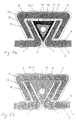
- the molded bodies 1 and 2 are shaped at the joint or in the joining area so that a foamed, non-positive and material connection is created between them by the foaming. In embodiment 6a, this is ensured by a hook-shaped flanging of the molded bodies 1 and 2.
- the connection profile 6 of the molded body 1 is again bent into a hook, twice by 90 °.
- the connection profile 6 of the second molded body 2 engages around this hook. It is bent or folded over in such a way that a hollow cylindrical joining clamp 10a with an opening 12 for introducing the connection profile 6 of the molded body 1 is formed.
- the second molded body 2 has the shape of a in its joining area and immediately thereafter Question mark ". The preformed shaped bodies 1 and 2 can thus be hooked into one another.
- 6b shows the joint connection after foaming.
- Foaming has resulted in a volume expansion of the moldings 1 and 2, preferably perpendicular to the thinner cover layer 5 two moldings 1 and 2 at a gap 12a open before foaming between facing outer layers 5 to each other and closed this gap 12a.
- the foamed supplementary profile 17 has the closed space 9 completely filled, and the moldings against each other pressed.
- each Shaped body 1 and 2 is provided with compression joints 20a and expansion joints 20b, to better ensure unrestricted foaming. This may be necessary be, if the thinner cover layers 5 are not flexible enough to one to ensure unimpeded foaming, for example due to their Thickness.
- To form the compression and expansion joints 20a and 20b are the Deckschischten 5 in the folding or bending area directly at the end and Provide continuous slots at the beginning of each radius. The width of the slots is the expected degree of foaming and the direction of foaming adjusted so that the metal strips bordering on the joints 20a and 20b cannot interfere with the foaming. Because of this, they are Compression joining 20a chosen wider than the expansion joints 20b, since here the Cover plates 5 seen from the respective molded body in the direction of its free end in Move towards the beginning of the radius and therefore a larger margin is advantageous.
- FIGS. 7a and 7b show a joint connection between two molded bodies 1 and 2 with one inserted assembly or receiving means 20.
- the moldings 1 and 2 are made as in the application examples described above each from an upper and a lower all-metal cover layer 3 and 5 and a middle foam layer 4. Similar to FIGS. 1a-4b, there is one on each of the shaped bodies 1 and 2 Connection profile 6 shaped to obtain a particularly secure press connection.
- the joining clip 10 is made of a fully metallic cover layer 14 and one Foam layer 15 constructed and shaped so that the mounting means, in Embodiment a sleeve 20, transverse to the longitudinal axis of the joining bracket 10th can be installed.
- the sleeve 20 can be screwed together from two or clamping halves. Rivet sleeves can also be used for this purpose or similar connecting elements are used. Care should be taken be that the sleeve 20 is made of a material that is not negative Has an effect on the joining clip 10, e.g. through contact corrosion with the Joining clamp material.
- the joining bracket 10 is with a through hole provided, the shape and size of the outer diameter of the Sleeve 20 corresponds and lies transversely to the longitudinal axis of the joining bracket.
- This hole can be made by conventional methods, e.g. made by drilling or punching become.
- the cavity 9 is completely filled with foam material, whereby the additionally installed sleeve 20 completely foamed and so, positively and non-positively firmly into the joining clamp is involved. It would also be possible to open an opening while foaming with a pin that is made of a material with a higher melting temperature than the temperature required for foaming and has the property no material connection with the foam material. After this complete completion of the frothing, the pen is pulled out again and so get a mounting hole. The foamed metal foam material was in In this case, foam around the inserted pen and after cooling and Pull out the pen, leaving an opening with the surface closed.
- the temperature control channel 18 is used for rapid cooling of the metal foam after the Foaming.
- a cooling fluid is guided through the temperature control channel 18.
- the joint can also be connected from the outside using suitable media, e.g. be cooled by a cold air flow.
- Figure 8 shows a cross composite of four shaped bodies 1 and 2. Between adjacent pairs of moldings 1 and 2 each have the joint connection of Figures 5a and 5b. It will be that described in Figures 5a and 5b Joining clamp 10 is used to produce each of these joining connections. In relation on the paired connection of moldings 1 and 2 is therefore on the Description of this embodiment.
- a cross-shaped joining clip 10 fulfills the function of a union clip.
- the Cap 10 is integrally formed with four perpendicular to each other standing staple legs protruding from a central area of the staple.
- the Cap can also consist of several joining clips of Figures 5a and 5b be composed, which are welded together, for example.
- everyone who Leg of the coupling clip 10 has the shape of the joining clip in cross section 10 of the embodiment of Figures 5a and 5b.
- the cap 10 is three layers with fully metallic outer cover layers 14 and 16 and an inner one Layer 15 of a foamed metal foam material.
- the cover layers 14 and 16 and the middle layer 15 of the cap 10 consist of the same Materials such as the cover sheets 14 and 16 and the foam material layers 15 of the further joining clamps 10 for the paired connections of shaped bodies 1 and 2nd
- the coupling clip 10 could also have two layers only with an outer, fully metallic top layer and a foam layer in the manner of Joining clips of Figures 1a to 4b may be formed.
- foamable metal foam material 15 of the cap 10 is by the same material as the supplementary profiles 17 formed. It would also be possible to Forming the layer 15 as a foam layer 15 a material with a lower Foaming temperature to use, which can be advantageous if the paired joint connections are already foamed before foaming for the Cap 10 is performed.
- layer 15 is a Foam layer
- the temperature control channels 18 also possible in the foaming of the coupling bracket 10, the joining areas of the paired joint connections by means of the temperature control channels 18 into the area of Cool the cap 10 in order to foam again to prevent. It would only be the temperature control channels 18 on their open end faces to connect with a cooling device for passing a cooling fluid.
- Figure 8 shows the cross composite after the foaming.
- the joining clips 10 in the Joining areas slipped over or pushed along and the temperature control channels 18 inserted with the threaded supplementary profiles 17.
- the supplementary profiles 17 are made of the metal foam material of the layer 15 of the coupling bracket 10 manufactured.
- the molded bodies 1, 2 already clamped in this way are then fixed in the position shown in Figure 8 and the cap 10 the four Joining clamps 10 are pressed across.
- the four molded bodies 1, 2 in the Cross composite desired position aligned and fixed to each other and immediately the union clamp 10 are placed on the molded bodies 1 and 2.
- the Joining clips 10 for connecting two adjoining two Shaped bodies 1 and 2 are in this type of connection to the Connection profiles of the molded body 1 and 2 pushed longitudinally and into the Cap 10 inserted, possibly pushing into the Cap 10 pressed into it. Then it becomes form-fitting Cross bond held together in an oven and placed on the Foaming temperature of the metal foam material is heated.
- foaming is the solid bond between the individual in a single foaming step Molded body pairs 1 and 2 and between the cap 10 and Joining clips 10 made at the cross point.
- the at least one temperature control channel 18 also creates the possibility of the foaming alone through an internal temperature control, namely internal heating, each of the joining areas.
- At least one temperature control channel 18 runs through each of the joining areas of the adjacent molded bodies 1 and 2. If it is in the cap 10 around a clip with foamable Metal foam material is, can be a temperature control channel or more Temperature control channels also in an intermediate area between the four Joining brackets 10 and the cap bracket 10 sitting thereon.
- the internal temperature control can be the only way to heat up Form foaming of the metal foam material in the joint area.
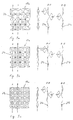
- Figures 9a, 9b, 9c show structured sheets 19a, 19b and 19c, from which the Spacers 19 used in the previous exemplary embodiments are produced can be, for example by means of a separation process.
- the sheets 19a, 19b and 19c are made of a material that has a sufficiently higher melting temperature than the temperature required for foaming.
- the plan as semi-finished products Sheets 19a, 19b and 19c are used for surface structuring by means of a corresponding tool evenly with bulges or pockets 21a, 21b and 21c.
- the structuring is preferably carried out by embossing in one Embossing tool.
- the pockets 21a, 21b and 21c are regular polyhedra, cones or truncated cones.
- the limiting side surfaces of the pockets run at an angle of 120 ° towards the bottom of each pocket.
- the pockets 21a, 21b and 21c are on theirs Bottom blunted flat. They can be closed at the bottom or open. By The reason for such a bag, which is open in the latter case, can be a tempering channel be passed through.
- each of the sheets 19a, 19b and 19c are in rows that are in two to each other vertical directions run parallel, densely packed next to each other arranged.
- each of the rows border on each pocket that is normal in one direction tapers to the bottom of the sheet before structuring, Pockets that face towards the bottom in the opposite normal direction rejuvenated.
- the pockets thus alternate with respect to the direction of taper in each Row and the row perpendicular to it. That is in the side view and the Cross sections A-A and B-B can be seen in each of FIGS. 9a, 9b and 9c.
- volume of each individual bag is half that expected average size of a foam bubble when joining foams material to be foamed.
- volume is understood to mean the space that from the delimiting side surfaces of each pocket and the edges of the Side surfaces connecting, flat top surfaces is included.
- FIG. 9d shows a spacer 19d formed from a sheet metal strip is curved in a jagged manner, the sheet metal sections for each jag in one To point angles of 120 ° to each other.
- the serrations form across the metal strip open pockets 21d.
- the spacer 19d is bent at one end so that it can be clamped to a temperature control channel 18.
- the Sheet metal beginning bent into a circular strokes 22 which have an inner diameter has, which is slightly smaller than an outer diameter of the temperature control channel.
- the sleeve 22 In order to push the spacer 19d onto the temperature control channel, the sleeve 22 widened by a corresponding piece in the elastic area and then into the the desired position is pushed on and clamped on the temperature control channel.
- the Holder sleeve 22 can also between the ends of the sheet metal strip, in particular in the Center, be formed to obtain a spacer on two sides.
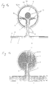
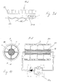
- FIG. 10 is a hollow cylinder profile 30 prepared for foaming in one Cross-section and a longitudinal section A-A shown.
- the hollow cylinder profile 30 is through a simple, circular tube with a single-layer hollow cylinder jacket formed from a metallic material.
- the hollow cylinder profile 30 becomes rigid with a metal foam material foamed.
- Figure 10 shows the hollow cylinder profile 30 immediately before Foaming.
- a temperature control channel 18 was previously in the form of an Comparison to the hollow cylinder profile 30 thin tube centrally in the hollow cylinder profile 30 inserted.
- the temperature control channel 18 is projecting radially from it Spacers 19 are held in their concentric position to the hollow cylinder profile 30. In this position, it projects through the hollow cylinder profile 30.
- the spacers 19 are formed by spacer rings along the Temperature control channel 18 are arranged at regular intervals and the Hold the temperature control channel 18 in its concentric position to the hollow cylinder profile 30. Between the spacers 19 are supplementary profiles 17 from one foamable metal foam material threaded onto the temperature control channel 18. The Spacers 19 are connected to the temperature control channel 18 with good thermal conductivity, so that you as temperature control surfaces in addition to that of the pipe jacket of the Temperature control channel 18 act.
- the spacers 19 of Figure 10 are each made by two planes. thin, narrow, concentric annular plates with radial connecting webs are formed. Instead could also be made from the spacer sheets of Figures 9a to c Structured sheets are used through which the flow channel 18 is centrally located guided and the outer peripheral edge of the inner cross section of the hollow cylinder profile 30 is adjusted.
- the sheet metal strips 19d of FIG. 9d could also be used as Spacers 19 can be used by moving them along the temperature control channel 18 in a number are postponed to the desired positioning of the Flow channel 18 is sufficient.
- the temperature control channel 18 is connected to a temperature control device on its open end faces 18a connected.
- the temperature control device 18a essentially consists of a Heater H and a cooler K and arranged in parallel in the temperature control circuit a pump P.
- the temperature control fluid is in the closed temperature control circuit from the pump P through a corresponding pipeline to the temperature control duct 18, through the temperature control channel 18 and through a corresponding pipeline the heater H or the cooler K promoted. This is done by means of a valve control Circuit either via heater H or cooler K. In this way, a external heating acting on the hollow cylinder profile 30 during foaming an interior heater supports.
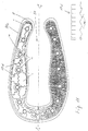
- Fig. 11 shows a horseshoe-shaped hollow profile 30a made of light metal in cross section a mast of a sailing yacht.
- the interior 31 obtained by the horseshoe shape Hollow profile 30a serves as a receptacle for a sail that can be rolled up.
- the hollow profile 30a has a cavity 9 enclosed on all sides. For stiffening the hollow profile 30a, the cavity 9 is foamed with a metal foam material.
- the hollow profile 30a is in a region to one side of a central longitudinal plane C-C immediately before foaming and in the area to the other side of the Central longitudinal plane C-C shown after foaming.
- the hollow profile 30a is cold-formed into a horseshoe shape from a semi-finished plate.
- the enclosed cavity 9 is also formed.
- a semi-finished plate is used, for example, by means of extrusion, in particular by means of hydrostatic extrusion, obtained finishing composite consisting of a fully metallic cover layer 3 and a layer 4 of one with the Top layer material metallurgically compatible, foamable Metal foam material.
- the covering layer 3 envelops after the hollow profile has been formed 30 the internal foam layer 4.
- the one after the other abutting ends of the semi-finished plate can advantageously by means of the joint connection described above be firmly connected. Other However, connections should not be excluded, for example one Welded joint.
- tempering channels 18 designed as tubes are inserted into the elongated, horseshoe-shaped cavity 9.
- Several of the spacers 19d of FIG. 9d are clamped onto the temperature control channels 18.
- Some of the spacers 19d are provided with clamping sleeves 22 at both ends and simultaneously clamped onto adjacent pairs of temperature control channels 18.
- a coherent temperature control structure is obtained in such a way that, due to its flexibility, any cavity shape can be adapted.
- the spacers 19d hold the temperature control channels 18 in the cavity 9 at the desired positions.
- the temperature control channels 18 are surrounded at those points with supplementary profiles 17 made of foamable metal foam material, where the foam layer 4 of the hollow profile 30 is not sufficient to completely foam the cavity 9.
- the supplementary profiles 17 are based on those already described in previous application examples Shashlik method "alternately threaded onto the temperature control channels 18 with spacers 19d.
- the hollow profile 30 is placed in an oven.
- the Temperature control channels 18 are used to pass a cooling fluid for controlled Stop foaming. It can be used to support the channels 18 Heat input from the outside also heat from the inside into the foam material in order to foam more evenly or even quickly enable. The heat input for foaming can also be done solely by means of Temperature control channels take place and so there is no need for an oven.
- the lower part of the cross section in FIG. 11 shows the hollow profile 30 after the Foaming process.
- the cavity 9 is complete and even with the foamed foam material filled.
- Foaming becomes one achieved a substantial increase in the strength of the hollow profile 30.
- Kink resistance and bending stiffness are not compared to one foamed hollow profile made of the same material and the same weight improved.
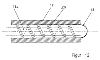
- Fig. 12 shows in a longitudinal section one of two nested Flow channels 18 and 18a existing flow channel pair that in one area is arranged with metal foam material 17.
- the area with the Metal foam material 17 can join the area within the above Embodiments described joining clip or another Area to be foamed, for example the hollow profile of the exemplary embodiment of Figure 11.
- the pair of flow channels is defined by an outer flow channel 18 and one therein concentrically mounted inner flow channel 18a formed.
- the outer Flow channel 18 is in direct contact with the surrounding one Metal foam material 17.
- the outer flow channel 18 is at one end closed, i.e. it is designed as a blind channel. At its open other end the outer flow channel 18 is connected to a temperature control device. By the open end of the inner flow channel 18a projects into the outer flow channel 18 in and reaches close to its closed end. Between the inner flow channel 18a and the outer flow channel 18 remains over the total length with which the inner flow channel 18a in the outer Flow channel 18 extends into an annular gap.
- volume 29 fulfills the two functions of storing the inner flow channel 18a in the outer flow channel 18 and the production of the best possible Heat transfer from the outer surface of the inner flow channel 18a the inner lateral surface of the outer flow channel 18.
- the temperature-resistant base material of the tape 29 fibers of another material woven in, which has a high thermal conductivity compared to the base material.
- the base material can be, for example, carbon fibers and the other way around better heat-conducting material can be formed by a metallic material.
- a The tape 29 fulfills the third function by the spiral winding on the inside Flow channel 18a.
- the spiral winding of the tape 29 creates in the Annulus between the two channels 18a and 18 is a spiral or thread-shaped return flow channel for the temperature control fluid.
- the temperature control fluid is by spirally winding the tape 29 on the inner flow channel 18a a flow path thus extended is returned to the temperature control device and in particular swirled so that a turbulent backflow with a compared to a laminar backflow increased heat transfer through the Annular gap takes place.
- the temperature control device hot tempering fluid introduced through the inner flow channel 18a.
- the introduced tempering fluid flows through the inner flow channel 18a up to it front end, flows around the front edge of the inner flow channel 18a outside and flows in the thread-shaped return flow channel through the band 29, several times around the inner flow channel 18 back to Temperature control device.
- the backflowing tempering fluid heats it Metal foam material 17 up to the foaming temperature, if necessary a piece about, on. Due to the heat exchange in countercurrent, the flow in the outside Temperature control fluid set a particularly uniform temperature. Corresponding the foaming process of the metal foam material 17 is uniform.
- the internal temperature control is not only used to heat the Metal foam material 17, but also for the controlled termination of the Foaming and preferably also for controlled cooling of the foamed material used.
- the temperature of the outside flowing tempering fluid after leaving the area with the Metal foam material 17 measured.
- the measurement is preferably carried out using a Temperature sensor which is arranged in the return flow channel.
- the sensor can be in the part of the return flow channel which is located in the foaming area and thus the temperature of the temperature control fluid directly in the area of the foaming measure up. However, it can also be located outside the foaming area Part of the return flow channel can be arranged.
- such a temperature sensor can also be used on any other suitable place in the circuit, as long as safe conclusions can be drawn from this can be drawn to the temperature in the frothing area.
- the Temperature control fluid does not have to be supplied in a closed circuit, but rather can also be generated by the temperature control device and after flowing through the inner Flow channel 18a and the outer flow channel 18 simply to the environment be given, if necessary after cleaning.
- the measured temperature is with a predetermined maximum temperature compared. Depending on the comparison, the heating process is continued or canceled. For example, if the specified maximum temperature is reached or reached or exceeded over a predetermined period of time, switches the temperature control system from heating to cooling. This can, for example, in the to the embodiment of Figure 10 described type.
- the cooling process can be reached when the temperature falls below or falls below a predetermined temperature same temperature sensor can be measured, canceled.
- the temperature sensor can advantageously be incorporated into the band 29. Includes the temperature control device for power generation with an internal combustion engine Turbocharger, the internal temperature control can take place in that the heating fluid Exhaust air from the internal combustion engine and the cooling air used as the supply air to the charger becomes. When switching, the exhaust air is switched to the supply air supply.
Landscapes
- Engineering & Computer Science (AREA)
- Mechanical Engineering (AREA)
- Manufacturing & Machinery (AREA)
- General Engineering & Computer Science (AREA)
- Chemical & Material Sciences (AREA)
- Composite Materials (AREA)
- Materials Engineering (AREA)
- Laminated Bodies (AREA)
- Casting Or Compression Moulding Of Plastics Or The Like (AREA)
- Molding Of Porous Articles (AREA)
- Processing And Handling Of Plastics And Other Materials For Molding In General (AREA)
Priority Applications (1)
| Application Number | Priority Date | Filing Date | Title |
|---|---|---|---|
| EP99123187A EP1004780A3 (fr) | 1998-11-24 | 1999-11-24 | Procédé d'assemblage pour connecter des articles |
Applications Claiming Priority (2)
| Application Number | Priority Date | Filing Date | Title |
|---|---|---|---|
| DE1998154173 DE19854173C2 (de) | 1998-11-24 | 1998-11-24 | Metallschaumformkörper |
| DE19854173 | 1998-11-24 |
Publications (3)
| Publication Number | Publication Date |
|---|---|
| EP1004376A2 true EP1004376A2 (fr) | 2000-05-31 |
| EP1004376A3 EP1004376A3 (fr) | 2000-12-13 |
| EP1004376B1 EP1004376B1 (fr) | 2005-01-12 |
Family
ID=7888841
Family Applications (1)
| Application Number | Title | Priority Date | Filing Date |
|---|---|---|---|
| EP19990123136 Expired - Lifetime EP1004376B1 (fr) | 1998-11-24 | 1999-11-19 | Article de mousse métallique |
Country Status (4)
| Country | Link |
|---|---|
| US (1) | US6468671B1 (fr) |
| EP (1) | EP1004376B1 (fr) |
| AT (1) | ATE286798T1 (fr) |
| DE (2) | DE19854173C2 (fr) |
Families Citing this family (4)
| Publication number | Priority date | Publication date | Assignee | Title |
|---|---|---|---|---|
| US7516529B2 (en) * | 2003-12-17 | 2009-04-14 | General Motors Corporation | Method for producing in situ metallic foam components |
| DE102004016134A1 (de) * | 2004-04-01 | 2005-11-03 | Bayerische Motoren Werke Ag | Kraftfahrzeug mit einem Dach |
| KR101068841B1 (ko) * | 2009-10-21 | 2011-09-30 | 한국원자력연구원 | 메탈폼을 이용한 동위원소 생산 대전류 고체표적 |
| JP5937304B2 (ja) * | 2011-06-15 | 2016-06-22 | フタバ産業株式会社 | セラミックヒータ |
Family Cites Families (21)
| Publication number | Priority date | Publication date | Assignee | Title |
|---|---|---|---|---|
| BE550320A (fr) * | 1955-08-22 | |||
| US3711363A (en) * | 1970-04-21 | 1973-01-16 | Ethyl Corp | Foamed core sandwich construction |
| US3848666A (en) * | 1970-11-19 | 1974-11-19 | Ethyl Corp | Foamed metal bodies |
| DE2147063A1 (de) * | 1970-11-23 | 1972-05-25 | VEB Kombinat Luft- und Kältetechnik, χ 8080 Dresden | Verfahren zur Verbindung von Bauteilen |
| DE2064443C3 (de) | 1970-12-30 | 1978-12-07 | Schlegel Gmbh, 2000 Hamburg | Anordnung zum Befestigen eines langgestreckten Gegenstands an einem paralellen Gegenstand, insbesondere zum Verbinden von Flugzeugwandverkleidungen |
| US3834881A (en) * | 1971-11-24 | 1974-09-10 | Ethyl Corp | Foamed metal article |
| JPS5473349A (en) * | 1977-11-22 | 1979-06-12 | Sumitomo Electric Ind Ltd | Long-sized heat pipe and method of the same |
| JPS60294A (ja) * | 1983-06-16 | 1985-01-05 | Matsushita Seiko Co Ltd | 発泡金属を用いた熱交換器 |
| JPS63271093A (ja) * | 1987-04-28 | 1988-11-08 | Mitsubishi Heavy Ind Ltd | シエルアンドチユ−ブ型蒸気発生装置 |
| DE4101630A1 (de) * | 1990-06-08 | 1991-12-12 | Fraunhofer Ges Forschung | Verfahren zur herstellung aufschaeumbarer metallkoerper und verwendung derselben |
| US5482533A (en) * | 1993-01-12 | 1996-01-09 | Fuji Jukogyo Kabushiki Kaisha | Method for manufacturing foam aluminum product and product |
| DE4318540A1 (de) * | 1993-06-04 | 1994-12-08 | Bayerische Motoren Werke Ag | Verfahren und Vorrichtung zur Herstellung eines Verbundbauteils |
| DE4426627C2 (de) * | 1993-07-29 | 1997-09-25 | Fraunhofer Ges Forschung | Verfahren zur Herstellung eines metallischen Verbundwerkstoffes |
| US5943543A (en) * | 1993-12-27 | 1999-08-24 | Hitachi Chemical Company, Ltd. | Heat transmitting member and method of manufacturing the same |
| DE4416371A1 (de) * | 1994-05-05 | 1995-11-09 | Admos Gleitlager Gmbh Berlin | Verfahren zur Herstellung langer poriger Metallschaumkörper |
| US5564064A (en) * | 1995-02-03 | 1996-10-08 | Mcdonnell Douglas Corporation | Integral porous-core metal bodies and in situ method of manufacture thereof |
| NO953858D0 (no) * | 1995-09-29 | 1995-09-29 | Norsk Hydro As | Laminat |
| DE19612781C1 (de) | 1996-03-29 | 1997-08-21 | Karmann Gmbh W | Bauteil aus metallischem Schaumwerkstoff, Verfahren zum Endformen dieses Bauteils und Vorrichtung zur Ausführung des Verfahrens |
| AT406649B (de) * | 1996-05-02 | 2000-07-25 | Mepura Metallpulver | Verfahren zur herstellung von porösen matrixmaterialien, insbesondere formkörpern, auf basis von metallen, und von halbzeug dafür |
| US5888600A (en) * | 1996-07-03 | 1999-03-30 | Henkel Corporation | Reinforced channel-shaped structural member |
| DE19648164C2 (de) * | 1996-11-21 | 2000-01-27 | Karmann Gmbh W | Karosserieteil, insbesondere Profilrahmenträger |
-
1998
- 1998-11-24 DE DE1998154173 patent/DE19854173C2/de not_active Expired - Fee Related
-
1999
- 1999-11-19 EP EP19990123136 patent/EP1004376B1/fr not_active Expired - Lifetime
- 1999-11-19 AT AT99123136T patent/ATE286798T1/de not_active IP Right Cessation
- 1999-11-19 DE DE59911439T patent/DE59911439D1/de not_active Expired - Fee Related
- 1999-11-24 US US09/448,257 patent/US6468671B1/en not_active Expired - Fee Related
Non-Patent Citations (1)
| Title |
|---|
| None |
Also Published As
| Publication number | Publication date |
|---|---|
| DE19854173A1 (de) | 2000-05-31 |
| DE59911439D1 (de) | 2005-02-17 |
| DE19854173C2 (de) | 2000-11-23 |
| US6468671B1 (en) | 2002-10-22 |
| EP1004376B1 (fr) | 2005-01-12 |
| EP1004376A3 (fr) | 2000-12-13 |
| ATE286798T1 (de) | 2005-01-15 |
Similar Documents
| Publication | Publication Date | Title |
|---|---|---|
| DE60209994T2 (de) | Wärmetauscherrohr | |
| DE69815901T2 (de) | Düsenstruktur für raketendüsen mit gekühlten düsenwänden | |
| DE60111469T2 (de) | Wärmetauscher und Verfahren zu dessen Herstellung | |
| EP3531055B1 (fr) | Échangeur de chaleur à plaques et son procédé de fabrication | |
| EP0226825B1 (fr) | Liaison d'un profilé creux avec une plaque en matière plastique, en particulier pour la fabrication d'échangeurs de chaleur | |
| DE3785686T2 (de) | Sammelrohrherstellungsverfahren und durch ein solches Verfahren erhaltenes Sammelrohr. | |
| DE69214635T2 (de) | Waermetauscher | |
| DE102009040544A1 (de) | Wärmeaustauscher mit einem Kältespeicher | |
| DE3425382C2 (de) | Verfahren zur Herstellung des Kernes eines Röhrenwärmeaustauschers | |
| EP1553379A1 (fr) | Echangeur de chaleur pour équipement industriel | |
| DE102005039672A1 (de) | Speicher für Kälte oder Wärme | |
| DE102005007591A1 (de) | Wärmetauscher | |
| DE10158627A1 (de) | Trägerstrukturen zur Aufnahme von Kräften und Verformungsenergie | |
| DE19854175C1 (de) | Metallschaumfügeverfahren | |
| DE3028096A1 (de) | Anpassungsverfahren eines metallrohres insbesondere fuer waermetauscher u.dgl. | |
| EP1004376B1 (fr) | Article de mousse métallique | |
| EP0907064A2 (fr) | Echangeur de chaleur, en particulier refroidisseur d'air pour centrale d'énergie, et procédé pour sa fabrication | |
| DE102006002932B4 (de) | Wärmetauscher und Herstellungsverfahren für Wärmetauscher | |
| DE20208748U1 (de) | Wärmeaustauschernetz, insbesondere für Hochtemperaturanwendungen | |
| EP3009780A1 (fr) | Fluide caloporteur | |
| DE102021117432A1 (de) | Verfahren zum Herstellen eines Konditionierelements, Konditionierelement sowie elektrischer Energiespeicher | |
| CH384008A (de) | Verfahren zur Herstellung von Wärmetauschern | |
| DE102005048407A1 (de) | Aus einem profilierten gerollten Metallprodukt hergestellte Röhre und Verfahren zur Herstellung derselben | |
| DE102015201808A1 (de) | Wärmetauscherrohranordnung und Verfahren zum Herstellen derselben | |
| DE102022116071A1 (de) | Temperierelement für Batterien |
Legal Events
| Date | Code | Title | Description |
|---|---|---|---|
| PUAI | Public reference made under article 153(3) epc to a published international application that has entered the european phase |
Free format text: ORIGINAL CODE: 0009012 |
|
| AK | Designated contracting states |
Kind code of ref document: A2 Designated state(s): AT BE CH CY DE DK ES FI FR GB GR IE IT LI LU MC NL PT SE |
|
| AX | Request for extension of the european patent |
Free format text: AL;LT;LV;MK;RO;SI |
|
| PUAL | Search report despatched |
Free format text: ORIGINAL CODE: 0009013 |
|
| AK | Designated contracting states |
Kind code of ref document: A3 Designated state(s): AT BE CH CY DE DK ES FI FR GB GR IE IT LI LU MC NL PT SE |
|
| AX | Request for extension of the european patent |
Free format text: AL;LT;LV;MK;RO;SI |
|
| RIC1 | Information provided on ipc code assigned before grant |
Free format text: 7B 22F 3/11 A, 7B 22F 7/00 B |
|
| 17P | Request for examination filed |
Effective date: 20010612 |
|
| AKX | Designation fees paid |
Free format text: AT BE CH CY DE DK ES FI FR GB GR IE IT LI LU MC NL PT SE |
|
| 17Q | First examination report despatched |
Effective date: 20030205 |
|
| GRAP | Despatch of communication of intention to grant a patent |
Free format text: ORIGINAL CODE: EPIDOSNIGR1 |
|
| GRAS | Grant fee paid |
Free format text: ORIGINAL CODE: EPIDOSNIGR3 |
|
| GRAA | (expected) grant |
Free format text: ORIGINAL CODE: 0009210 |
|
| AK | Designated contracting states |
Kind code of ref document: B1 Designated state(s): AT BE CH CY DE DK ES FI FR GB GR IE IT LI LU MC NL PT SE |
|
| PG25 | Lapsed in a contracting state [announced via postgrant information from national office to epo] |
Ref country code: NL Free format text: LAPSE BECAUSE OF FAILURE TO SUBMIT A TRANSLATION OF THE DESCRIPTION OR TO PAY THE FEE WITHIN THE PRESCRIBED TIME-LIMIT Effective date: 20050112 Ref country code: IT Free format text: LAPSE BECAUSE OF FAILURE TO SUBMIT A TRANSLATION OF THE DESCRIPTION OR TO PAY THE FEE WITHIN THE PRE;WARNING: LAPSES OF ITALIAN PATENTS WITH EFFECTIVE DATE BEFORE 2007 MAY HAVE OCCURRED AT ANY TIME BEFORE 2007. THE CORRECT EFFECTIVE DATE MAY BE DIFFERENT FROM THE ONE RECORDED.SCRIBED TIME-LIMIT Effective date: 20050112 Ref country code: IE Free format text: LAPSE BECAUSE OF FAILURE TO SUBMIT A TRANSLATION OF THE DESCRIPTION OR TO PAY THE FEE WITHIN THE PRESCRIBED TIME-LIMIT Effective date: 20050112 Ref country code: GB Free format text: LAPSE BECAUSE OF FAILURE TO SUBMIT A TRANSLATION OF THE DESCRIPTION OR TO PAY THE FEE WITHIN THE PRESCRIBED TIME-LIMIT Effective date: 20050112 Ref country code: FR Free format text: LAPSE BECAUSE OF NON-PAYMENT OF DUE FEES Effective date: 20050112 Ref country code: FI Free format text: LAPSE BECAUSE OF FAILURE TO SUBMIT A TRANSLATION OF THE DESCRIPTION OR TO PAY THE FEE WITHIN THE PRESCRIBED TIME-LIMIT Effective date: 20050112 |
|
| REG | Reference to a national code |
Ref country code: GB Ref legal event code: FG4D Free format text: NOT ENGLISH |
|
| REG | Reference to a national code |
Ref country code: CH Ref legal event code: EP |
|
| REF | Corresponds to: |
Ref document number: 59911439 Country of ref document: DE Date of ref document: 20050217 Kind code of ref document: P |
|
| REG | Reference to a national code |
Ref country code: IE Ref legal event code: FG4D Free format text: GERMAN |
|
| PG25 | Lapsed in a contracting state [announced via postgrant information from national office to epo] |
Ref country code: SE Free format text: LAPSE BECAUSE OF FAILURE TO SUBMIT A TRANSLATION OF THE DESCRIPTION OR TO PAY THE FEE WITHIN THE PRESCRIBED TIME-LIMIT Effective date: 20050412 Ref country code: DK Free format text: LAPSE BECAUSE OF FAILURE TO SUBMIT A TRANSLATION OF THE DESCRIPTION OR TO PAY THE FEE WITHIN THE PRESCRIBED TIME-LIMIT Effective date: 20050412 |
|
| PG25 | Lapsed in a contracting state [announced via postgrant information from national office to epo] |
Ref country code: ES Free format text: LAPSE BECAUSE OF FAILURE TO SUBMIT A TRANSLATION OF THE DESCRIPTION OR TO PAY THE FEE WITHIN THE PRESCRIBED TIME-LIMIT Effective date: 20050423 |
|
| NLV1 | Nl: lapsed or annulled due to failure to fulfill the requirements of art. 29p and 29m of the patents act | ||
| GBV | Gb: ep patent (uk) treated as always having been void in accordance with gb section 77(7)/1977 [no translation filed] |
Effective date: 20050112 |
|
| REG | Reference to a national code |
Ref country code: IE Ref legal event code: FD4D |
|
| PG25 | Lapsed in a contracting state [announced via postgrant information from national office to epo] |
Ref country code: CY Free format text: LAPSE BECAUSE OF FAILURE TO SUBMIT A TRANSLATION OF THE DESCRIPTION OR TO PAY THE FEE WITHIN THE PRESCRIBED TIME-LIMIT Effective date: 20051119 Ref country code: AT Free format text: LAPSE BECAUSE OF NON-PAYMENT OF DUE FEES Effective date: 20051119 |
|
| PLBE | No opposition filed within time limit |
Free format text: ORIGINAL CODE: 0009261 |
|
| STAA | Information on the status of an ep patent application or granted ep patent |
Free format text: STATUS: NO OPPOSITION FILED WITHIN TIME LIMIT |
|
| PG25 | Lapsed in a contracting state [announced via postgrant information from national office to epo] |
Ref country code: MC Free format text: LAPSE BECAUSE OF NON-PAYMENT OF DUE FEES Effective date: 20051130 Ref country code: LU Free format text: LAPSE BECAUSE OF NON-PAYMENT OF DUE FEES Effective date: 20051130 Ref country code: LI Free format text: LAPSE BECAUSE OF NON-PAYMENT OF DUE FEES Effective date: 20051130 Ref country code: CH Free format text: LAPSE BECAUSE OF NON-PAYMENT OF DUE FEES Effective date: 20051130 Ref country code: BE Free format text: LAPSE BECAUSE OF NON-PAYMENT OF DUE FEES Effective date: 20051130 |
|
| 26N | No opposition filed |
Effective date: 20051013 |
|
| EN | Fr: translation not filed | ||
| PG25 | Lapsed in a contracting state [announced via postgrant information from national office to epo] |
Ref country code: DE Free format text: LAPSE BECAUSE OF NON-PAYMENT OF DUE FEES Effective date: 20060601 |
|
| REG | Reference to a national code |
Ref country code: CH Ref legal event code: PL |
|
| BERE | Be: lapsed |
Owner name: STREUBER, FRITZ MICHAEL Effective date: 20051130 |
|
| PG25 | Lapsed in a contracting state [announced via postgrant information from national office to epo] |
Ref country code: PT Free format text: LAPSE BECAUSE OF NON-PAYMENT OF DUE FEES Effective date: 20050612 |
|
| PG25 | Lapsed in a contracting state [announced via postgrant information from national office to epo] |
Ref country code: GR Free format text: LAPSE BECAUSE OF NON-PAYMENT OF DUE FEES Effective date: 20050112 |