EP1004380A1 - Fraise de précision avec plaquette de coupe - Google Patents
Fraise de précision avec plaquette de coupe Download PDFInfo
- Publication number
- EP1004380A1 EP1004380A1 EP99118127A EP99118127A EP1004380A1 EP 1004380 A1 EP1004380 A1 EP 1004380A1 EP 99118127 A EP99118127 A EP 99118127A EP 99118127 A EP99118127 A EP 99118127A EP 1004380 A1 EP1004380 A1 EP 1004380A1
- Authority
- EP
- European Patent Office
- Prior art keywords
- cutting
- insert
- tool body
- tool according
- plates
- Prior art date
- Legal status (The legal status is an assumption and is not a legal conclusion. Google has not performed a legal analysis and makes no representation as to the accuracy of the status listed.)
- Granted
Links
Images


Classifications
-
- B—PERFORMING OPERATIONS; TRANSPORTING
- B23—MACHINE TOOLS; METAL-WORKING NOT OTHERWISE PROVIDED FOR
- B23C—MILLING
- B23C5/00—Milling-cutters
- B23C5/02—Milling-cutters characterised by the shape of the cutter
- B23C5/10—Shank-type cutters, i.e. with an integral shaft
- B23C5/109—Shank-type cutters, i.e. with an integral shaft with removable cutting inserts
-
- B—PERFORMING OPERATIONS; TRANSPORTING
- B23—MACHINE TOOLS; METAL-WORKING NOT OTHERWISE PROVIDED FOR
- B23C—MILLING
- B23C5/00—Milling-cutters
-
- B—PERFORMING OPERATIONS; TRANSPORTING
- B23—MACHINE TOOLS; METAL-WORKING NOT OTHERWISE PROVIDED FOR
- B23C—MILLING
- B23C3/00—Milling particular work; Special milling operations; Machines therefor
- B23C3/28—Grooving workpieces
- B23C3/30—Milling straight grooves, e.g. keyways
-
- B—PERFORMING OPERATIONS; TRANSPORTING
- B23—MACHINE TOOLS; METAL-WORKING NOT OTHERWISE PROVIDED FOR
- B23C—MILLING
- B23C2220/00—Details of milling processes
- B23C2220/36—Production of grooves
- B23C2220/366—Turbine blade grooves
-
- Y—GENERAL TAGGING OF NEW TECHNOLOGICAL DEVELOPMENTS; GENERAL TAGGING OF CROSS-SECTIONAL TECHNOLOGIES SPANNING OVER SEVERAL SECTIONS OF THE IPC; TECHNICAL SUBJECTS COVERED BY FORMER USPC CROSS-REFERENCE ART COLLECTIONS [XRACs] AND DIGESTS
- Y10—TECHNICAL SUBJECTS COVERED BY FORMER USPC
- Y10T—TECHNICAL SUBJECTS COVERED BY FORMER US CLASSIFICATION
- Y10T407/00—Cutters, for shaping
- Y10T407/19—Rotary cutting tool
- Y10T407/1906—Rotary cutting tool including holder [i.e., head] having seat for inserted tool
- Y10T407/1908—Face or end mill
- Y10T407/1924—Specified tool shape
-
- Y—GENERAL TAGGING OF NEW TECHNOLOGICAL DEVELOPMENTS; GENERAL TAGGING OF CROSS-SECTIONAL TECHNOLOGIES SPANNING OVER SEVERAL SECTIONS OF THE IPC; TECHNICAL SUBJECTS COVERED BY FORMER USPC CROSS-REFERENCE ART COLLECTIONS [XRACs] AND DIGESTS
- Y10—TECHNICAL SUBJECTS COVERED BY FORMER USPC
- Y10T—TECHNICAL SUBJECTS COVERED BY FORMER US CLASSIFICATION
- Y10T407/00—Cutters, for shaping
- Y10T407/19—Rotary cutting tool
- Y10T407/1906—Rotary cutting tool including holder [i.e., head] having seat for inserted tool
- Y10T407/1926—Plural simultaneously usable separable tools in common seat or common clamp actuator for plural simultaneously usable tools
-
- Y—GENERAL TAGGING OF NEW TECHNOLOGICAL DEVELOPMENTS; GENERAL TAGGING OF CROSS-SECTIONAL TECHNOLOGIES SPANNING OVER SEVERAL SECTIONS OF THE IPC; TECHNICAL SUBJECTS COVERED BY FORMER USPC CROSS-REFERENCE ART COLLECTIONS [XRACs] AND DIGESTS
- Y10—TECHNICAL SUBJECTS COVERED BY FORMER USPC
- Y10T—TECHNICAL SUBJECTS COVERED BY FORMER US CLASSIFICATION
- Y10T407/00—Cutters, for shaping
- Y10T407/19—Rotary cutting tool
- Y10T407/1906—Rotary cutting tool including holder [i.e., head] having seat for inserted tool
- Y10T407/1934—Rotary cutting tool including holder [i.e., head] having seat for inserted tool with separate means to fasten tool to holder
-
- Y—GENERAL TAGGING OF NEW TECHNOLOGICAL DEVELOPMENTS; GENERAL TAGGING OF CROSS-SECTIONAL TECHNOLOGIES SPANNING OVER SEVERAL SECTIONS OF THE IPC; TECHNICAL SUBJECTS COVERED BY FORMER USPC CROSS-REFERENCE ART COLLECTIONS [XRACs] AND DIGESTS
- Y10—TECHNICAL SUBJECTS COVERED BY FORMER USPC
- Y10T—TECHNICAL SUBJECTS COVERED BY FORMER US CLASSIFICATION
- Y10T407/00—Cutters, for shaping
- Y10T407/19—Rotary cutting tool
- Y10T407/1946—Face or end mill
Definitions
- the invention relates to a cutting tool, in particular a milling tool for precision machining, which is equipped with detachably attached cutting inserts.
- HSS high-speed steel
- the grooves usually have one Fir tree profile and are undercut several times. On the shape of the grooves is very demanding posed.
- HSS cutters have to be reground from time to time become.
- the outer contour of the Frasers defines the contour of the groove to be machined
- the cutter contour cannot be changed during regrinding.
- the open spaces are usually arched formed on the cutting edge, i.e. provided with a radial relief. Regrinding of the HSS milling cutter is then done by regrinding the rake face without machining the free face, which is only causes a small reduction in diameter.
- the cutting tool solves this task with the Features of claim 1.
- the solution the task by applying the method according to claim 18 allows.
- the cutting tool according to the invention has several Plate seats on which to accommodate accordingly trained cutting plates are set up.
- Each Insert seat is assigned at least one insert, that belongs to at least one insert set.
- each insert set exactly one insert for each insert seat contains.
- the insert can be released from the insert seat repeatedly and attached to it without causing a Dimensional tolerance arises.
- the tool body serves both as Tool body in the true sense as well as Insert holder for the fine machining of the inserts. This can reduce the accuracy of the cutting edges be significantly greater than the accuracy of the insert seats.
- the inserts are preferred provided with an individual marking that the Designated plate seat to which they are assigned.
- the mark can be an engraving, a color marking or a be special shape or another permanent Labeling that the subsequent edits survives.
- the latter can be achieved by the Plate seats each have their own shapes. This can, however, with an additional manufacturing expenditure be connected.
- a marking can also be provided be the tool body. This prevents that the insert is wrong at another tolerances having tool body is attached.
- the cutting edges of the inserts complement each other to at least one complete cutting edge, in particular overlap areas in tooth tip areas can be provided in which the number of cutting edges z> 1 is. In this way, the cutting edge wear from arranged obliquely and parallel to the axis of rotation Cutting edges are aligned with each other.
- the insert seats be marked with a simple Allow assignment of the insert markings.
- the Markers can be used as symbols, as numbers or as Letter code can be provided.
- the inserts are preferably with a positive Provide clearance angle.
- the clearance angle is determined by a Preserve bevel after the cutting edge.
- the open space lies on a straight line that extends extends from the cutting edge. This is the clearance angle also immediately after the cutting edge different from zero. This allows milling with a positive rake angle in the opposite direction, i.e. the cutting edge moves due to the rotation of the milling tool on the workpiece against the feed direction of the tool. This also results in a good surface quality high cutting speeds.
- the inserts are preferably with an axial rake angle built in from 0 °, along each cutting edge results in constant cutting conditions.
- the inserts are preferably offset spirally (arranged on a helix) to the To even cutting forces. This also has advantages with regard to chip removal. One also arises relatively uniform and lower in peak value force acting radially on the cutting tool. Elastic deformations and thus machining inaccuracies are minimized.
- the cutting plates are, for example, in a Sintering processes have been made before and immediately after the first installation in a tool body provided with the appropriate marking that the respective Features seat and tool body.
- the inserts are then in ground using a precision grinding process so that the Outer contour or the cutting edge geometry of the milling tool is set precisely.
- the inserts are removed and another Processing fed.
- This can be a targeted fillet the cutting edges and a surface treatment, such as the coating with titanium nitride (TiN), titanium carbide (TiC), titanium carbonitride (TiCN), titanium aluminum nitride (TiAlN) or other hard materials, a PVD coating or similar his. Doing so will mark the insert not destroyed and remains legible. Consequently a set of inserts is ready. More insert sets can in the same way for the same tool body getting produced. The insert sets are assigned to the tool body and intended only for this.
- the tool body is then with the appropriately sorted and packaged insert sets delivered.
- the user can see the tool body on site equip with cutting plates of one set and these if necessary, for example, against wear, against cutting inserts replace another insert set.
- an entire insert set is exchanged. With low accuracy requirements it is however, it is also possible to exchange individual inserts. This allows for particularly loaded cutting inserts Provide additional copies.
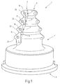
- a profile milling cutter 1 is illustrated in FIG. 1, such as for machining the profile groove in a turbine rotor usable for the base of a turbine blade is.
- a turbine rotor is, for example, that of the DE 19611276 C1.
- the profile milling cutter 1 has one Tool body 2 on one end 3 with a receptacle is provided for a work spindle. On his The tool body 2 has an opposite end about the profile corresponding to the groove to be machined.
- Two flutes 4, 5 are formed in the longitudinal direction, in which plate seats 6, 7, 8, 9 are formed.
- To the Insert seats 11, 12, 13, 14 are held.
- the cutting plates 11, 12, 13, 14 are each with a central fastening screw 15, 16, 17, 18 clamped and pressed against the seat 6, 7, 8, 9.
- Each insert 11, 12, 13, 14 each has at least one a cutting edge 21, 22, 23, 24 on the The outer contour of the milling tool is determined.
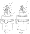
- the cutting inserts 11 to 14 are, as can be seen in particular from FIG. 3 results, e.g. arranged on a straight line.
- the cutting edges 21 to 24 thus complement one another continuous cutting edge. Accordingly, the Rake faces and the free surfaces of the cutting plates 11, 12, 13, 14 to each other without paragraphs.
- the open spaces are ground so that there is a positive clearance angle is.
- the radial rake angle is preferably set to be positive and the axial rake angle is preferably zero.
- the upper section and its tooth tip are active, while the cutting edges 21a, 22a, 23a, 24a with their respective lower area and their tooth tip active are.
- the number of cutting edges is z Tooth tip is 2, while it is otherwise 1.
- All of the profile milling cutters 1 is a Plate seat according to Figure 5 provided.
- the record seat has a flat bearing surface 27, which is approximately the contour corresponds to the respective insert, so that this supported on almost the entire back (base area) is. Close to the support surface 27 perpendicular to each other and to the base 27 Contact surfaces 28, 29 on the corresponding side surfaces 31, 32 of the cutting plate 11, 12, 13 or 14 assigned are.
- the cutting plate 11 is representative illustrated for all other inserts. The right-angled alignment of the contact surfaces 28, 29 too the bearing surface 27 results in a safe and repeatable Storage of the cutting plate 11. The exact position the insert 11 is of tolerances of the insert seat 6 and the cutting plate 11 dependent.
- the mark 34 contains, for example, several groups of digits 37, 38, 39.
- the first group of digits 37 corresponds to a number XX of the tool body 2, which characterizes this individual.
- All tool bodies of the concerned can be Tool design with an individual number XX be that clearly identifies the tool body and different from other tool bodies.
- the second group of digits 38 is, for example, the insert seat identifying number.
- the profile milling cutter 1 has a total of eight insert seats, so that the second group of digits 38 is a number between 1 and 8 can serve.
- a last group of digits 39 can be the number of the insert set for which the relevant Insert 11 heard. That way ensure that only one and the same Insert set of inserts on the tool body 2 can be installed.
- the tool body 2 is on or at its insert seat 6 and the other plate seats with the marking 35 provided at least the number XX of the tool body as group of digits 37 'and the number YY of the insert seat reproduces as a group of digits 38 '.
- a number or group of numbers PP attached to the cutting plates 11 to 14 and 11a to 14a be used to identify the profile, i.e. the cutting shape defined by the cutting inserts serves.
- a number or group of numbers PP attached to the cutting plates 11 to 14 and 11a to 14a be used to identify the profile, i.e. the cutting shape defined by the cutting inserts serves.
- the tool body 2 are on their respective panel seats, initially with individual key figures XX and numbered YY.
- the the tool body identifying digits XX can be on any Record seat or placed in a single other location become. E.g. they are engraved.
- the tool body 2 are assembled from insert blanks Inserted blank insert sets that one insert for each insert seat 6, 7, 8, 9 11, 12, 13, 14 still include in the form of a blank.
- Each insert blank is then marked 34 provided, as number group XX the number of the tool body, as a group of digits YY the individual Plate seat and as number group ZZ the number of the Reproduces insert set to which it belongs.
- the respective tool seat assigned to it becomes the tool body picked up by a precision grinding machine and there are the cutting edges 21, 22, 23, 24 as well the corresponding cutting edges 21a, 22a, 23a, 24a form and precisely positioned by the corresponding areas the cutting plates 11, 12, 13, 14 (11a, 12a, 13a, 14a) are ground on their corresponding surfaces.
- the cutting plates 11, 12, 13, 14 are for example their open spaces and, if necessary, also on their rake surfaces ground.
- Grinding edges of the profile cutter 1 with the required Accuracy.
- the cutting plates 11, 12, 13, 14 and 11a 12a, 13a, 14a removed and the inserts of the next insert set assembled. These are in turn with a corresponding one Marking has been provided.
- the cutting plates 11 to 14a of the individual insert sets of a further one Treatment supplied can, for example, targeted rounding the cutting edges and / or the coating of the Inserts with a hard material layer.
- the hard material layer is, for example, a few ⁇ m thick, so that a through the grinding processing achieved accuracy of, for example, ⁇ 1/100 mm is not affected in the slightest.
- the profile milling cutter 1 can immediately be used for precision machining, For example, for finishing milling appropriately shaped Grooves.
- the inserts of the next insert set where each Inserts with the number groups XX, YY on the insert seats be assembled using the same group of digits Wear XX, YY. This way when inserting the insert the accuracy produced by fine grinding regarding the position and shape of the cutting edges reproduced.
- a cutting tool (form or profile cutter) 1 has a tool body 2 with insert seats 6, 7, 8, 9 on which inserts 11, 12, 13, 14 firmly and individually assigned.
- the cutting plates 11, 12, 13, 14 belong to a set of inserts.
- To the cutting tool 1 also include other insert sets individually assigned to the plate seats 6, 7, 8, 9 Inserts 11, 12, 13, 14.
Landscapes
- Engineering & Computer Science (AREA)
- Mechanical Engineering (AREA)
- Milling Processes (AREA)
- Cutting Tools, Boring Holders, And Turrets (AREA)
- Drilling Tools (AREA)
Applications Claiming Priority (2)
| Application Number | Priority Date | Filing Date | Title |
|---|---|---|---|
| DE19855045 | 1998-11-28 | ||
| DE19855045A DE19855045C2 (de) | 1998-11-28 | 1998-11-28 | Mit Schneidplatten bestückter Präzisionsfräser |
Publications (2)
| Publication Number | Publication Date |
|---|---|
| EP1004380A1 true EP1004380A1 (fr) | 2000-05-31 |
| EP1004380B1 EP1004380B1 (fr) | 2003-03-05 |
Family
ID=7889395
Family Applications (1)
| Application Number | Title | Priority Date | Filing Date |
|---|---|---|---|
| EP99118127A Expired - Lifetime EP1004380B1 (fr) | 1998-11-28 | 1999-09-11 | Fraise de précision avec plaquette de coupe |
Country Status (8)
| Country | Link |
|---|---|
| US (1) | US6322296B1 (fr) |
| EP (1) | EP1004380B1 (fr) |
| JP (1) | JP2000254812A (fr) |
| KR (1) | KR20000052375A (fr) |
| CN (1) | CN1116142C (fr) |
| AT (1) | ATE233630T1 (fr) |
| DE (2) | DE19855045C2 (fr) |
| ES (1) | ES2189326T3 (fr) |
Cited By (3)
| Publication number | Priority date | Publication date | Assignee | Title |
|---|---|---|---|---|
| DE10043015A1 (de) * | 2000-09-01 | 2002-03-21 | Walter Ag | Zerspanungswerkzeug mit direkter Schneidplattenanlage |
| EP2070619A3 (fr) * | 2007-12-11 | 2009-07-29 | United Technologies Corporation | Procédé d'usinage d'un disque de turbine |
| WO2019094997A1 (fr) * | 2017-11-15 | 2019-05-23 | Ceratizit Austria Gesellschaft M.B.H. | Outil à enlèvement de copeaux confectionné pour expédition |
Families Citing this family (51)
| Publication number | Priority date | Publication date | Assignee | Title |
|---|---|---|---|---|
| US20030138301A1 (en) * | 2000-06-13 | 2003-07-24 | Hubertus Kuerzel | Method for milling fishbone-type notches |
| US6487947B1 (en) * | 2000-08-25 | 2002-12-03 | Steven M. Clai | Device for reaming pipe |
| DE10159431B4 (de) * | 2001-12-04 | 2005-10-20 | Mapal Fab Praezision | Werkzeug zur Feinstbearbeitung von Oberflächen |
| DE10222445A1 (de) * | 2002-05-22 | 2003-12-04 | Horn P Hartmetall Werkzeugfab | Schneidplatte für ein Bearbeitungswerkzeug sowie Halter für eine derartige Schneidplatte |
| DE10245197B4 (de) * | 2002-09-27 | 2006-05-18 | Walter Ag | Verfahren zum Fräsen von tiefen Nuten zur Herstellung mehreren zueinander paralleler, hinsichtlich der Fräsbearbeitung instabiler Wänden an einem Werkstück |
| US7007382B2 (en) * | 2003-07-24 | 2006-03-07 | United Technologies Corporation | Slot machining |
| US7134811B2 (en) * | 2003-10-24 | 2006-11-14 | Kennametal Inc. | Helical end mill type cutter configured to compensate for radial runout |
| US8939683B1 (en) * | 2004-12-21 | 2015-01-27 | Robert Alvin White | Inverse square tool form |
| JP2007021675A (ja) * | 2005-07-19 | 2007-02-01 | Asahi Diamond Industrial Co Ltd | 総形回転切削工具及びその製造方法 |
| US10335891B2 (en) | 2006-09-28 | 2019-07-02 | GM Global Technology Operations LLC | Weld face design for spot welding |
| US8436269B2 (en) | 2006-09-28 | 2013-05-07 | GM Global Technology Operations LLC | Welding electrode with contoured face |
| US8927894B2 (en) | 2006-09-28 | 2015-01-06 | GM Global Technology Operations LLC | Weld electrode for attractive weld appearance |
| SE530527C2 (sv) * | 2007-02-08 | 2008-07-01 | Seco Tools Ab | Skärverktyg med multipla kanaler som definierar olika profiler samt metod |
| DK3351326T3 (da) * | 2007-02-26 | 2021-11-15 | Greenleaf Tech Corporation | Rilleforarbejdningsfremgangsmåde |
| WO2008123375A1 (fr) * | 2007-03-30 | 2008-10-16 | Kyocera Corporation | Outil de coupe et procédé de coupe utilisant l'outil |
| JP4945382B2 (ja) * | 2007-09-06 | 2012-06-06 | 株式会社東芝 | 溝切削加工方法および溝切削加工装置 |
| US8393419B1 (en) * | 2008-03-13 | 2013-03-12 | Us Synthetic Corporation | Superabrasive elements having indicia and related apparatus and methods |
| US9174292B2 (en) * | 2008-04-16 | 2015-11-03 | United Technologies Corporation | Electro chemical grinding (ECG) quill and method to manufacture a rotor blade retention slot |
| JP5224902B2 (ja) * | 2008-05-14 | 2013-07-03 | 株式会社東芝 | 総型回転切削工具および溝切削加工装置並びに溝切削加工方法 |
| US8226334B2 (en) * | 2008-06-23 | 2012-07-24 | The Boeing Company | Variable diameter cutting tool |
| US8511949B2 (en) * | 2008-07-30 | 2013-08-20 | Osg Corporation | Method of cutting tree-shaped groove and rotary cutting tool |
| KR101236094B1 (ko) | 2008-08-29 | 2013-02-21 | 오에스지 가부시키가이샤 | 스로어웨이식 절삭 회전 공구 |
| US7846010B2 (en) * | 2008-09-10 | 2010-12-07 | United Technologies Corporation | Notched grind wheel and method to manufacture a rotor blade retention slot |
| JP5198579B2 (ja) * | 2008-11-13 | 2013-05-15 | オーエスジー株式会社 | スローアウェイ式切削回転工具 |
| JP5342310B2 (ja) * | 2009-04-10 | 2013-11-13 | 三菱重工業株式会社 | 組立式工具 |
| JP5368158B2 (ja) * | 2009-04-23 | 2013-12-18 | オーエスジー株式会社 | インデキサブル式ホロータップ |
| JP2011020250A (ja) * | 2009-07-15 | 2011-02-03 | Hitachi Tool Engineering Ltd | 翼根溝加工用刃先交換式切削工具 |
| US9266178B2 (en) | 2010-01-07 | 2016-02-23 | Black & Decker Inc. | Power tool having rotary input control |
| US9475180B2 (en) | 2010-01-07 | 2016-10-25 | Black & Decker Inc. | Power tool having rotary input control |
| US9440305B2 (en) | 2010-04-28 | 2016-09-13 | GM Global Technology Operations LLC | Method of resistance spot welding aluminum alloy workpieces |
| JP5641204B2 (ja) * | 2010-06-02 | 2014-12-17 | 日立ツール株式会社 | クリスマスカッタおよび、これを用いたタービン翼根部の切削加工方法 |
| MX2012010763A (es) * | 2010-08-06 | 2012-10-15 | Saint Gobain Abrasives Inc | Herramienta abrasiva y metodo para acabar formas complejas en piezas de trabajo. |
| US9403222B2 (en) | 2010-12-02 | 2016-08-02 | Osg Corporation | Method of removing end-surface burr of formed groove and formed rotary cutting tool for chamfering |
| KR101233332B1 (ko) | 2010-12-20 | 2013-02-14 | 두산중공업 주식회사 | 터빈 로터의 더브테일 가공 툴 장치 |
| CN102764910A (zh) * | 2011-05-03 | 2012-11-07 | 富泰华工业(深圳)有限公司 | 成型铣刀 |
| CN102717138A (zh) * | 2012-06-01 | 2012-10-10 | 上海交通大学 | 轮盘圆弧曲线榫槽精加工可重构成形铣刀 |
| JP2014166669A (ja) * | 2013-02-28 | 2014-09-11 | Mitsubishi Heavy Ind Ltd | 総形回転切削工具 |
| US20150202788A1 (en) * | 2014-01-17 | 2015-07-23 | Automatik Plastics Machinery Gmbh | Pelletizing device with a cutting rotor |
| WO2016054649A1 (fr) * | 2014-10-03 | 2016-04-07 | Costa Larry J | Système de prise de vues montable sur broche |
| CN105562801A (zh) * | 2014-10-17 | 2016-05-11 | 基准精密工业(惠州)有限公司 | 铣刀 |
| JP2016190299A (ja) * | 2015-03-31 | 2016-11-10 | 三菱マテリアル株式会社 | 総形エンドミル |
| CN105171083B (zh) * | 2015-08-28 | 2017-08-04 | 东方电气集团东方汽轮机有限公司 | 机夹式菌型叶根铣刀 |
| CN105215444B (zh) * | 2015-09-28 | 2018-05-04 | 长沙鼓风机厂有限责任公司 | 一种罗茨鼓风机叶轮曲面型线加工专用机夹铣刀 |
| US10610956B2 (en) | 2016-02-04 | 2020-04-07 | GM Global Technology Operations LLC | Welding electrode cutting tool and method of using the same |
| US10456856B2 (en) | 2016-02-04 | 2019-10-29 | GM Global Technology Operations LLC | Welding electrode cutting tool and method of using the same |
| JP6817717B2 (ja) * | 2016-04-07 | 2021-01-20 | 三菱マテリアル株式会社 | フライスカッタ、切削インサート及びフライス加工方法 |
| US10612119B2 (en) * | 2016-11-23 | 2020-04-07 | GM Global Technology Operations LLC | Surface roughening tool and method |
| DE102017102473B4 (de) | 2017-02-08 | 2025-03-27 | Franken Gmbh & Co. Kg Fabrik Für Präzisionswerkzeuge | Fräswerkzeug, insbesondere Tannenbaumfräser, und Herstellungsverfahren für ein Fräswerkzeug |
| CN107096953B (zh) * | 2017-05-22 | 2019-02-15 | 重庆强锐科技有限公司 | 一种硬质合金型线铣刀 |
| US12151391B2 (en) | 2019-08-02 | 2024-11-26 | Roger Kent | Coping cut machine for carpentry molding |
| US11529691B2 (en) * | 2019-12-02 | 2022-12-20 | Kennametal Inc. | Rotary cutting tool with hybrid cutting insert design |
Citations (5)
| Publication number | Priority date | Publication date | Assignee | Title |
|---|---|---|---|---|
| JPS5621711A (en) * | 1979-07-24 | 1981-02-28 | Sumitomo Electric Ind Ltd | Drilling tool |
| EP0278389A2 (fr) * | 1987-02-06 | 1988-08-17 | Ingersoll Maschinen Und Werkzeuge Gesellschaft Mit Beschränkter Haftung | Plaquette de coupe pour fraise et fraise equipée d'une telle plaquette de coupe |
| DE3812150A1 (de) * | 1988-03-02 | 1989-09-14 | Amram Dotany | Spiralverzahntes zerspanungswerkzeug |
| EP0711619A1 (fr) * | 1994-11-11 | 1996-05-15 | Mitsubishi Materials Corporation | Fraise à queue avec plaquettes de coupe |
| US5791832A (en) * | 1994-04-28 | 1998-08-11 | Kyocera Corporation | Throw-away tip for milling cutters |
Family Cites Families (12)
| Publication number | Priority date | Publication date | Assignee | Title |
|---|---|---|---|---|
| US3859700A (en) * | 1974-05-07 | 1975-01-14 | Illinois Tool Works | Inserted blade cutter |
| IN151108B (fr) * | 1978-09-13 | 1983-02-19 | Standard Oil Co | |
| US4790693A (en) | 1987-02-06 | 1988-12-13 | Ingersoll Cutting Tool Company | Interfitting on-edge inserts for milling cutters |
| GB8925360D0 (en) * | 1989-11-09 | 1989-12-28 | Sandvik Ltd | Milling cutters |
| US5391616A (en) | 1993-12-22 | 1995-02-21 | General Electric Company | Polycarbonate compositions comprising thermoplastic olefin copolymers |
| JP3628695B2 (ja) * | 1994-01-14 | 2005-03-16 | サンドビック アクティエボラーグ | スローアウェイチップおよび切削工具 |
| JPH08187609A (ja) * | 1995-01-10 | 1996-07-23 | Mitsubishi Materials Corp | 凹r付きスロ−アウエイチップ |
| DE19607230C1 (de) * | 1996-02-27 | 1997-02-20 | Walter Ag | Verfahren zur Herstellung bogenförmiger Nuten und Werkzeug dazu |
| DE19611276C1 (de) * | 1996-03-22 | 1997-03-20 | Walter Ag | Zerspanungswerkzeug und Verfahren zur Herstellung von hinterschnittenen Nuten |
| FR2765507A1 (fr) * | 1997-07-07 | 1999-01-08 | Safety Fabrique De Carbure De | Fraise hemispherique et plaquette pour une telle fraise |
| US5908269A (en) * | 1997-08-05 | 1999-06-01 | Siemens Westinghouse Power Corporation | Helical cutter geometry for a cutting tool used to manufacture turbine rotors |
| US5944456A (en) * | 1997-12-04 | 1999-08-31 | Kennametal Inc. | Three dimensional mill and milling inserts |
-
1998
- 1998-11-28 DE DE19855045A patent/DE19855045C2/de not_active Expired - Fee Related
-
1999
- 1999-09-11 EP EP99118127A patent/EP1004380B1/fr not_active Expired - Lifetime
- 1999-09-11 DE DE59904433T patent/DE59904433D1/de not_active Expired - Fee Related
- 1999-09-11 ES ES99118127T patent/ES2189326T3/es not_active Expired - Lifetime
- 1999-09-11 AT AT99118127T patent/ATE233630T1/de not_active IP Right Cessation
- 1999-11-23 US US09/447,970 patent/US6322296B1/en not_active Expired - Fee Related
- 1999-11-25 JP JP11333579A patent/JP2000254812A/ja active Pending
- 1999-11-25 KR KR1019990052624A patent/KR20000052375A/ko not_active Withdrawn
- 1999-11-29 CN CN99120992A patent/CN1116142C/zh not_active Expired - Fee Related
Patent Citations (5)
| Publication number | Priority date | Publication date | Assignee | Title |
|---|---|---|---|---|
| JPS5621711A (en) * | 1979-07-24 | 1981-02-28 | Sumitomo Electric Ind Ltd | Drilling tool |
| EP0278389A2 (fr) * | 1987-02-06 | 1988-08-17 | Ingersoll Maschinen Und Werkzeuge Gesellschaft Mit Beschränkter Haftung | Plaquette de coupe pour fraise et fraise equipée d'une telle plaquette de coupe |
| DE3812150A1 (de) * | 1988-03-02 | 1989-09-14 | Amram Dotany | Spiralverzahntes zerspanungswerkzeug |
| US5791832A (en) * | 1994-04-28 | 1998-08-11 | Kyocera Corporation | Throw-away tip for milling cutters |
| EP0711619A1 (fr) * | 1994-11-11 | 1996-05-15 | Mitsubishi Materials Corporation | Fraise à queue avec plaquettes de coupe |
Non-Patent Citations (1)
| Title |
|---|
| PATENT ABSTRACTS OF JAPAN vol. 5, no. 68 (M - 067) 8 May 1981 (1981-05-08) * |
Cited By (5)
| Publication number | Priority date | Publication date | Assignee | Title |
|---|---|---|---|---|
| DE10043015A1 (de) * | 2000-09-01 | 2002-03-21 | Walter Ag | Zerspanungswerkzeug mit direkter Schneidplattenanlage |
| DE10043015C2 (de) * | 2000-09-01 | 2002-09-19 | Walter Ag | Zerspanungswerkzeug mit direkter Schneidplattenanlage |
| US6692197B2 (en) | 2000-09-01 | 2004-02-17 | Walter Aktiengesellschaft Ag | Metal cutting tool with direct cutting plate arrangement |
| EP2070619A3 (fr) * | 2007-12-11 | 2009-07-29 | United Technologies Corporation | Procédé d'usinage d'un disque de turbine |
| WO2019094997A1 (fr) * | 2017-11-15 | 2019-05-23 | Ceratizit Austria Gesellschaft M.B.H. | Outil à enlèvement de copeaux confectionné pour expédition |
Also Published As
| Publication number | Publication date |
|---|---|
| KR20000052375A (ko) | 2000-08-25 |
| ATE233630T1 (de) | 2003-03-15 |
| CN1116142C (zh) | 2003-07-30 |
| ES2189326T3 (es) | 2003-07-01 |
| EP1004380B1 (fr) | 2003-03-05 |
| DE19855045A1 (de) | 2000-06-08 |
| DE59904433D1 (de) | 2003-04-10 |
| CN1259413A (zh) | 2000-07-12 |
| US6322296B1 (en) | 2001-11-27 |
| DE19855045C2 (de) | 2003-01-02 |
| JP2000254812A (ja) | 2000-09-19 |
Similar Documents
| Publication | Publication Date | Title |
|---|---|---|
| EP1004380B1 (fr) | Fraise de précision avec plaquette de coupe | |
| DE10291948C5 (de) | Spanwerkzeug mit verbesserter Schneidplättchensitzanordnung für austauschbare Schneidplättchen | |
| EP0792709B1 (fr) | Méthode à usiner des rainures courbées et outil destiné à cet usinage | |
| EP0964762B1 (fr) | Fraise de percage circulaire avec plaquettes amovibles et sieges de plaquette associes | |
| WO2008012254A2 (fr) | Fraiseuse de vilebrequins | |
| DE3211727C2 (de) | Werkzeug zur zerspanenden Bearbeitung von Zahnflanken | |
| AT398049B (de) | Werkzeugträger zum wirbeln bzw. schälen von aussengewinden, schnecken und profilen | |
| EP0485546B1 (fr) | Garniture de coupe pour outils | |
| WO2019034199A1 (fr) | Outil de fraisage pour une machine-outil, ensemble de fraisage pourvu de l'outil de fraisage ainsi que procédé pour fabriquer une cage à languettes | |
| EP1901873A1 (fr) | Procede d'usinage de vilebrequins par enlevement de copeaux et dispositif permettant la mise en oeuvre dudit procede | |
| DE102006016626A1 (de) | Schneideinsatz und Verfahren zur spanenden Bearbeitung von rotierend bewegten Werkstücken | |
| DE102006014972B4 (de) | Kombiniertes Bearbeitungsverfahren und Bearbeitungseinrichtung | |
| DE202019001722U1 (de) | Anfasanordnung | |
| EP0264822A2 (fr) | Taraud | |
| EP0912283B1 (fr) | Fraisage a grande vitesse | |
| DE102004008166A1 (de) | Werkzeug zur spanenden Bearbeitung von Präzisionsbohrungen | |
| WO2005077575A9 (fr) | Procede d'usinage par enlevement de copeaux de trous de precision | |
| DE3909643C2 (de) | Mehrschneidenwerkzeugkopf zur spanabhebenden Vor- und Feinbearbeitung mit kreisförmiger Schnittbewegung | |
| DE102005058731A1 (de) | Vorrichtung und Verfahren zum Erzeugen von Hinterlegungen sowie ein Messerkopf | |
| DE3504296C2 (fr) | ||
| DE29723558U1 (de) | Fräswerkzeug | |
| DE69716060T2 (de) | Verfahren zur herstellung von schneidwerkzeugen | |
| DE202009014144U1 (de) | Ausklinkwerkzeug | |
| DE3111771C2 (fr) | ||
| DE8627969U1 (de) | Gewindebohrer |
Legal Events
| Date | Code | Title | Description |
|---|---|---|---|
| PUAI | Public reference made under article 153(3) epc to a published international application that has entered the european phase |
Free format text: ORIGINAL CODE: 0009012 |
|
| AK | Designated contracting states |
Kind code of ref document: A1 Designated state(s): AT BE CH CY DE DK ES FI FR GB GR IE IT LI LU MC NL PT SE |
|
| AX | Request for extension of the european patent |
Free format text: AL;LT;LV;MK;RO;SI |
|
| 17P | Request for examination filed |
Effective date: 20000710 |
|
| RIN1 | Information on inventor provided before grant (corrected) |
Inventor name: HUBER ROLF Inventor name: WETLI MARKUS |
|
| AKX | Designation fees paid |
Free format text: AT BE CH CY DE DK ES FI FR GB GR IE IT LI LU MC NL PT SE |
|
| 17Q | First examination report despatched |
Effective date: 20011026 |
|
| GRAH | Despatch of communication of intention to grant a patent |
Free format text: ORIGINAL CODE: EPIDOS IGRA |
|
| GRAH | Despatch of communication of intention to grant a patent |
Free format text: ORIGINAL CODE: EPIDOS IGRA |
|
| GRAA | (expected) grant |
Free format text: ORIGINAL CODE: 0009210 |
|
| AK | Designated contracting states |
Designated state(s): AT BE CH CY DE DK ES FI FR GB GR IE IT LI LU MC NL PT SE |
|
| PG25 | Lapsed in a contracting state [announced via postgrant information from national office to epo] |
Ref country code: NL Free format text: LAPSE BECAUSE OF FAILURE TO SUBMIT A TRANSLATION OF THE DESCRIPTION OR TO PAY THE FEE WITHIN THE PRESCRIBED TIME-LIMIT Effective date: 20030305 Ref country code: IT Free format text: LAPSE BECAUSE OF FAILURE TO SUBMIT A TRANSLATION OF THE DESCRIPTION OR TO PAY THE FEE WITHIN THE PRESCRIBED TIME-LIMIT;WARNING: LAPSES OF ITALIAN PATENTS WITH EFFECTIVE DATE BEFORE 2007 MAY HAVE OCCURRED AT ANY TIME BEFORE 2007. THE CORRECT EFFECTIVE DATE MAY BE DIFFERENT FROM THE ONE RECORDED. Effective date: 20030305 Ref country code: IE Free format text: LAPSE BECAUSE OF FAILURE TO SUBMIT A TRANSLATION OF THE DESCRIPTION OR TO PAY THE FEE WITHIN THE PRESCRIBED TIME-LIMIT Effective date: 20030305 Ref country code: GR Free format text: LAPSE BECAUSE OF FAILURE TO SUBMIT A TRANSLATION OF THE DESCRIPTION OR TO PAY THE FEE WITHIN THE PRESCRIBED TIME-LIMIT Effective date: 20030305 Ref country code: FR Free format text: LAPSE BECAUSE OF NON-PAYMENT OF DUE FEES Effective date: 20030305 Ref country code: FI Free format text: LAPSE BECAUSE OF FAILURE TO SUBMIT A TRANSLATION OF THE DESCRIPTION OR TO PAY THE FEE WITHIN THE PRESCRIBED TIME-LIMIT Effective date: 20030305 |
|
| REG | Reference to a national code |
Ref country code: GB Ref legal event code: FG4D Free format text: NOT ENGLISH |
|
| REG | Reference to a national code |
Ref country code: CH Ref legal event code: EP |
|
| GBT | Gb: translation of ep patent filed (gb section 77(6)(a)/1977) |
Effective date: 20030305 |
|
| REG | Reference to a national code |
Ref country code: IE Ref legal event code: FG4D Free format text: GERMAN |
|
| REF | Corresponds to: |
Ref document number: 59904433 Country of ref document: DE Date of ref document: 20030410 Kind code of ref document: P |
|
| REG | Reference to a national code |
Ref country code: SE Ref legal event code: TRGR |
|
| PG25 | Lapsed in a contracting state [announced via postgrant information from national office to epo] |
Ref country code: PT Free format text: LAPSE BECAUSE OF FAILURE TO SUBMIT A TRANSLATION OF THE DESCRIPTION OR TO PAY THE FEE WITHIN THE PRESCRIBED TIME-LIMIT Effective date: 20030605 Ref country code: DK Free format text: LAPSE BECAUSE OF FAILURE TO SUBMIT A TRANSLATION OF THE DESCRIPTION OR TO PAY THE FEE WITHIN THE PRESCRIBED TIME-LIMIT Effective date: 20030605 |
|
| REG | Reference to a national code |
Ref country code: ES Ref legal event code: FG2A Ref document number: 2189326 Country of ref document: ES Kind code of ref document: T3 |
|
| NLV1 | Nl: lapsed or annulled due to failure to fulfill the requirements of art. 29p and 29m of the patents act | ||
| PG25 | Lapsed in a contracting state [announced via postgrant information from national office to epo] |
Ref country code: LU Free format text: LAPSE BECAUSE OF NON-PAYMENT OF DUE FEES Effective date: 20030911 Ref country code: GB Free format text: LAPSE BECAUSE OF NON-PAYMENT OF DUE FEES Effective date: 20030911 Ref country code: CY Free format text: LAPSE BECAUSE OF FAILURE TO SUBMIT A TRANSLATION OF THE DESCRIPTION OR TO PAY THE FEE WITHIN THE PRESCRIBED TIME-LIMIT Effective date: 20030911 Ref country code: AT Free format text: LAPSE BECAUSE OF NON-PAYMENT OF DUE FEES Effective date: 20030911 |
|
| PG25 | Lapsed in a contracting state [announced via postgrant information from national office to epo] |
Ref country code: SE Free format text: LAPSE BECAUSE OF NON-PAYMENT OF DUE FEES Effective date: 20030912 Ref country code: ES Free format text: LAPSE BECAUSE OF NON-PAYMENT OF DUE FEES Effective date: 20030912 |
|
| PG25 | Lapsed in a contracting state [announced via postgrant information from national office to epo] |
Ref country code: MC Free format text: LAPSE BECAUSE OF NON-PAYMENT OF DUE FEES Effective date: 20030930 Ref country code: LI Free format text: LAPSE BECAUSE OF NON-PAYMENT OF DUE FEES Effective date: 20030930 Ref country code: CH Free format text: LAPSE BECAUSE OF NON-PAYMENT OF DUE FEES Effective date: 20030930 Ref country code: BE Free format text: LAPSE BECAUSE OF NON-PAYMENT OF DUE FEES Effective date: 20030930 |
|
| REG | Reference to a national code |
Ref country code: IE Ref legal event code: FD4D Ref document number: 1004380E Country of ref document: IE |
|
| PLBE | No opposition filed within time limit |
Free format text: ORIGINAL CODE: 0009261 |
|
| STAA | Information on the status of an ep patent application or granted ep patent |
Free format text: STATUS: NO OPPOSITION FILED WITHIN TIME LIMIT |
|
| EN | Fr: translation not filed | ||
| 26N | No opposition filed |
Effective date: 20031208 |
|
| BERE | Be: lapsed |
Owner name: *WALTER A.G. Effective date: 20030930 |
|
| GBPC | Gb: european patent ceased through non-payment of renewal fee |
Effective date: 20030911 |
|
| EUG | Se: european patent has lapsed | ||
| REG | Reference to a national code |
Ref country code: CH Ref legal event code: PL |
|
| REG | Reference to a national code |
Ref country code: ES Ref legal event code: FD2A Effective date: 20030912 |
|
| PGFP | Annual fee paid to national office [announced via postgrant information from national office to epo] |
Ref country code: DE Payment date: 20050930 Year of fee payment: 7 |
|
| PG25 | Lapsed in a contracting state [announced via postgrant information from national office to epo] |
Ref country code: DE Free format text: LAPSE BECAUSE OF NON-PAYMENT OF DUE FEES Effective date: 20070403 |