EP1004391B1 - Procédé et dispositif d' usinage et de durcissement au laser pour matrices rotatives - Google Patents
Procédé et dispositif d' usinage et de durcissement au laser pour matrices rotatives Download PDFInfo
- Publication number
- EP1004391B1 EP1004391B1 EP99123505A EP99123505A EP1004391B1 EP 1004391 B1 EP1004391 B1 EP 1004391B1 EP 99123505 A EP99123505 A EP 99123505A EP 99123505 A EP99123505 A EP 99123505A EP 1004391 B1 EP1004391 B1 EP 1004391B1
- Authority
- EP
- European Patent Office
- Prior art keywords
- cutting blade
- laser
- cutting
- machining
- blade
- Prior art date
- Legal status (The legal status is an assumption and is not a legal conclusion. Google has not performed a legal analysis and makes no representation as to the accuracy of the status listed.)
- Expired - Lifetime
Links
- 238000000034 method Methods 0.000 title claims description 17
- 238000003754 machining Methods 0.000 title abstract description 43
- 238000005520 cutting process Methods 0.000 claims abstract description 120
- 229910001315 Tool steel Inorganic materials 0.000 claims abstract description 8
- 238000004519 manufacturing process Methods 0.000 claims abstract description 7
- 239000000463 material Substances 0.000 claims description 22
- 229910000831 Steel Inorganic materials 0.000 claims description 3
- 239000010959 steel Substances 0.000 claims description 3
- 239000002184 metal Substances 0.000 description 6
- 230000000295 complement effect Effects 0.000 description 3
- 210000001331 nose Anatomy 0.000 description 3
- 230000002093 peripheral effect Effects 0.000 description 3
- 238000010276 construction Methods 0.000 description 2
- 239000011261 inert gas Substances 0.000 description 2
- 238000003801 milling Methods 0.000 description 2
- 239000011087 paperboard Substances 0.000 description 2
- 239000002893 slag Substances 0.000 description 2
- 238000010521 absorption reaction Methods 0.000 description 1
- 230000002411 adverse Effects 0.000 description 1
- 230000000712 assembly Effects 0.000 description 1
- 238000000429 assembly Methods 0.000 description 1
- 239000011111 cardboard Substances 0.000 description 1
- 238000007796 conventional method Methods 0.000 description 1
- 230000001419 dependent effect Effects 0.000 description 1
- 238000013461 design Methods 0.000 description 1
- 238000011161 development Methods 0.000 description 1
- 230000018109 developmental process Effects 0.000 description 1
- 210000000887 face Anatomy 0.000 description 1
- 239000011888 foil Substances 0.000 description 1
- 238000010438 heat treatment Methods 0.000 description 1
- 230000002452 interceptive effect Effects 0.000 description 1
- 239000007769 metal material Substances 0.000 description 1
- 238000012986 modification Methods 0.000 description 1
- 230000004048 modification Effects 0.000 description 1
- 239000000123 paper Substances 0.000 description 1
- 239000002985 plastic film Substances 0.000 description 1
- 229920006255 plastic film Polymers 0.000 description 1
- 238000010791 quenching Methods 0.000 description 1
- 230000000171 quenching effect Effects 0.000 description 1
- 230000005855 radiation Effects 0.000 description 1
Images
Classifications
-
- B—PERFORMING OPERATIONS; TRANSPORTING
- B23—MACHINE TOOLS; METAL-WORKING NOT OTHERWISE PROVIDED FOR
- B23P—METAL-WORKING NOT OTHERWISE PROVIDED FOR; COMBINED OPERATIONS; UNIVERSAL MACHINE TOOLS
- B23P15/00—Making specific metal objects by operations not covered by a single other subclass or a group in this subclass
- B23P15/28—Making specific metal objects by operations not covered by a single other subclass or a group in this subclass cutting tools
- B23P15/40—Making specific metal objects by operations not covered by a single other subclass or a group in this subclass cutting tools shearing tools
- B23P15/406—Making specific metal objects by operations not covered by a single other subclass or a group in this subclass cutting tools shearing tools rotary or plane die cutters
-
- B—PERFORMING OPERATIONS; TRANSPORTING
- B23—MACHINE TOOLS; METAL-WORKING NOT OTHERWISE PROVIDED FOR
- B23K—SOLDERING OR UNSOLDERING; WELDING; CLADDING OR PLATING BY SOLDERING OR WELDING; CUTTING BY APPLYING HEAT LOCALLY, e.g. FLAME CUTTING; WORKING BY LASER BEAM
- B23K26/00—Working by laser beam, e.g. welding, cutting or boring
- B23K26/36—Removing material
- B23K26/362—Laser etching
- B23K26/364—Laser etching for making a groove or trench, e.g. for scribing a break initiation groove
-
- B—PERFORMING OPERATIONS; TRANSPORTING
- B23—MACHINE TOOLS; METAL-WORKING NOT OTHERWISE PROVIDED FOR
- B23K—SOLDERING OR UNSOLDERING; WELDING; CLADDING OR PLATING BY SOLDERING OR WELDING; CUTTING BY APPLYING HEAT LOCALLY, e.g. FLAME CUTTING; WORKING BY LASER BEAM
- B23K2103/00—Materials to be soldered, welded or cut
- B23K2103/02—Iron or ferrous alloys
- B23K2103/04—Steel or steel alloys
-
- C—CHEMISTRY; METALLURGY
- C21—METALLURGY OF IRON
- C21D—MODIFYING THE PHYSICAL STRUCTURE OF FERROUS METALS; GENERAL DEVICES FOR HEAT TREATMENT OF FERROUS OR NON-FERROUS METALS OR ALLOYS; MAKING METAL MALLEABLE, e.g. BY DECARBURISATION OR TEMPERING
- C21D1/00—General methods or devices for heat treatment, e.g. annealing, hardening, quenching or tempering
- C21D1/06—Surface hardening
- C21D1/09—Surface hardening by direct application of electrical or wave energy; by particle radiation
-
- C—CHEMISTRY; METALLURGY
- C21—METALLURGY OF IRON
- C21D—MODIFYING THE PHYSICAL STRUCTURE OF FERROUS METALS; GENERAL DEVICES FOR HEAT TREATMENT OF FERROUS OR NON-FERROUS METALS OR ALLOYS; MAKING METAL MALLEABLE, e.g. BY DECARBURISATION OR TEMPERING
- C21D9/00—Heat treatment, e.g. annealing, hardening, quenching or tempering, adapted for particular articles; Furnaces therefor
- C21D9/22—Heat treatment, e.g. annealing, hardening, quenching or tempering, adapted for particular articles; Furnaces therefor for drills; for milling cutters; for machine cutting tools
Definitions
- This invention relates to a method of making a rotary die cylinder, in particular for rotary die cutting of blanks from thin sheets or webs of material.
- the thin web is of a material such as paper, paperboard, cardboard, plastic film, metal foil, thin sheet metal, and the like.
- US-A-4,608,895 discloses a pair of rotary dies which are made from a cylindrical blank of tool steel which is hardened and then ground to produce a cylindrical surface before it is electrical discharge machined (EDM) to produce cutting blades on the surface of the dies with the desired geometry to cut the blanks.
- the cutting blades are formed on the rotary dies after the steel of the rotary dies is hardened to prevent the deformation which would occur if the cutting blades were formed and then the rotary dies were heat treated to harden the cutting blades. While these rotary dies have been sold commercially and performed satisfactorily for relatively high volume mass production operations, they are expensive and difficult both to manufacture and re-sharpen when they become worn or dull in use.
- US-A-5,575,185 discloses a pair of rotary dies having coacting cutting blades projecting generally radially outwardly from the main body of each rotary die. These rotary dies are formed of unhardened tool steel and the cutting blades may be formed by machining with conventional cutting tools. After the cutting blades are formed by machining, the cutting blades are hardened by heating to an elevated temperature with a laser and quenching them without substantially hardening the core or body of the workpiece and hence without distorting the core or body of the workpiece by heat treating it. Thus, this system obviates the need for EDM machining which reduces the cost to produce rotary dies.
- EP-A-0 191 203 discloses an apparatus and method for fabricating cutting tools and tool cutting edges (cutting blades) wherein an intense radiation beam such as generated by a laser is used to form or sharpen a previously formed cutting edge portion and additionally to anneal or harden material adjacent to and/or including the cutting edge to improve its physical characteristics.
- the rough machining with conventional cutting tools and the final machining and heat treating by a laser are performed with the same machine tool, such as a computerized numerical control (CNC) machining center.
- CNC computerized numerical control
- Such a machining center permits rapid and accurate rough machining as well as accurate final laser machining of the cutting blades.
- the more accurate final machining accomplished by a laser produces a more accurately formed cutting blade and also simultaneously heat treats the blade with minimal distortion of the blade and without significant distortion of the core or body of the cylinder.
- Objects, features and advantages of this invention are to provide a pair of rotary die cylinders with co-acting cutting blades which are easier and more accurately formed, can be initially rough formed with conventional cutting tools, are precisely formed into their final shape by a laser which simultaneously heat treats the cutting blade, can be heat treated and hardened without substantial distortion of the cutting blade or the die cylinder, provide a clean and accurate cut of a blank from a web of material, are of relatively simple design and economical manufacture and assembly and have a long in service useful life and may be formed by a method which is more accurate, faster, easier and less expensive than current methods of making the rotary die cylinders.
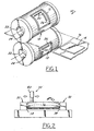
- FIG. 1 illustrates a pair of rotary die cylinders 10 embodying this invention and having co-acting cutting blades 12,13 thereon which, when the cylinders 10 are co-rotating, cut generally rectangular blanks 14 from a web 16 of thin material, such as paperboard, passing through the nip 18 of the cylinders 10.
- a web 16 of thin material such as paperboard
- FIG. 1 illustrates a pair of rotary die cylinders 10 embodying this invention and having co-acting cutting blades 12,13 thereon which, when the cylinders 10 are co-rotating, cut generally rectangular blanks 14 from a web 16 of thin material, such as paperboard, passing through the nip 18 of the cylinders 10.
- a web 16 of thin material such as paperboard
- each die cylinder 10 is journalled for rotation by a pair of arbor assemblies having co-axial spindles with opposed noses (not shown) received in complementary recesses 22 in the opposed ends of each die cylinder 10.
- Each recess 22 is preferably a bore with a frustoconical side wall tapered inwardly from its associated cylinder end which provides a locator surface engageable with a complementary tapered surface on the nose of an associated spindle.
- the frustoconical surfaces of both its recesses 22 are on the same or common axis of rotation of the cylinder 10.
- each cylinder 10 is driven through one or both spindles of its arbor assembly to co-rotate in opposed directions of rotation with essentially the same peripheral surface speed of its cutting blades 12,13.
- One or both spindles are also coupled to their associated cylinder for rotation therewith by a key (not shown) received in a keyway 24 in the recess 22 of a cylinder 10.
- a key (not shown) received in a keyway 24 in the recess 22 of a cylinder 10.
- the die cylinders 10 are constructed so that the position of the cutting edges of the co-acting blades 12,13 can be varied and adjusted by moving the dies axially and/or in rotary phase relationship with respect to each other. This is accomplished by locating various portions of the cutting edge of the cutting blades 12,13 of each die 10 so that relative movement of the dies 10 in one axial direction and/or one rotary phase direction causes all the axially and circumferentially extending cutting edge portions of the blades 12,13 of both dies 10 to move toward and even overlap each other, and movement in the opposite axial and rotary phase direction causes all the cutting edges of the blades 12,13 of both dies to move away and even be spaced from each other.
- the blades 12,13 also have crossover portions 26 at which the cutting action between the blades 12,13 shifts over from one edge to the other edge of each blade such as from the inner edge to the outer edge of blade 12 and the outer edge to the inner edge of blade 13.
- suitable rotary dies 10 having cutting blades 12,13 and crossovers 26 which permit such relative adjustment of the rotary dies are disclosed in U.S. Patent No. 5,575,185, the disclosure of which is incorporated herein by reference in its entirety, and hence will not be described in further detail.
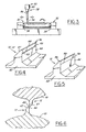
- the rotary die cylinders 10 can be made by machining with conventional cutting tools (FIG. 2), a cylinder of unhardened tool steel to substantially form the lands and crossovers of the cutting blades 12,13 and thereafter form the final desired shape of the cutting blades 12, 13 and simultaneously heat treat them with a laser 28 (FIG. 3).
- the tool steel workpiece may be initially hardened to a moderate hardness which still permits machining by conventional tools.
- both the initial machining with conventional cutting tools and the final machining with the laser 28 are performed on a computer numerical control (CNC) machining center to facilitate quickly and accurately forming the cutting blades 12, 13 on the die cylinders 10.
- CNC computer numerical control
- the final machining by the laser 28 provides an extremely accurate, cutting blade 12, 13 and also simultaneously heat treats substantially only the cutting blade 12, 13 and not the die cylinder body, to avoid distortion of the cutting blades 12, 13 which would adversely affect their geometry and performance.
- the cylinder 10 is accurately located and rotated in a machine tool 30 by arbors 32 with spindles 34 having complementary noses 36 engaging the recesses 22 in the ends of the cylinder 10.
- peripheral portions of the cylinder 10 are machined away in rough cuts by a milling tool 38 rotated and moved along various axes by the tool spindle 40 in coordination with angular or arcuate rotary movement of the cylinder about its axis by the arbor spindles 34.
- the coordinated movement of the spindle 40 and the cylinder 10 is performed by a CNC machine tool 30 having at least three orthogonal axes of movement of the spindles relative to the workpiece and one arcuate or rotary axis of movement of the workpiece relative to the spindle.
- this machining is performed on a so-called five axis or six axis CNC machine tool. After the general contour of the cutting blades has been formed, inclined or beveled edges can be machined with an end milling tool received in the spindle of the CNC machine tool.
- the cutting blade 12',13' has a base 42 adjacent the body of the cylinder 10 and narrowing into a middle portion 44 which narrows still further to a tip 46 of the cutting blade 12, 13.
- the tip 46 has a beveled back face 47, an elongate land portion 48 and a generally flat leading face 50 generally transverse to the land 48 and extending slightly outwardly of or overhanging the middle portion 44 of the cutting blade 12',13'.
- This leading face 50 overhangs the adjacent middle portion 44 of the cutting blade 12 by only about 0,025 to 0,635 mm (0.001 to 0.025), and by about 0,076 to 0,508 mm (0.003 to 0.020 of an inch), providing a slight step or shoulder 52 between them.
- the laser 28 replaces the conventional cutting tool in the spindle 40 of the CNC machine tool 30 to simultaneously final machine and heat treat the cutting blade 12',13' to harden it.
- the emitter 54 of the laser 28 can be received in the spindle 40 of the CNC machine tool for orienting and manipulating it to direct its laser beam 56 onto the cutting blades 12',13' while the cylinder 10 is received and located by its recesses 22 on the arbors 32 of the machine tool 30.
- the laser beam 56 is very small, typically on the order of about 0,127 to 0,254 mm (five to ten thousandths of an inch) in diameter, is highly accurate and is typically surrounded by a stream of inert gas to provide a controlled environment for the laser machining. Due to the relatively small size of the laser beam 56, only a small amount of material is removed by the beam 56 at any given time. Thus, a substantial portion of the cutting blade 12 is formed by the rough machining process with conventional tools with only a small portion finish machined by the laser 28. Typically, 30 to 60% of the total machining time of a typical rotary die cylinder 10 is spent forming the comers, crossover portions, and other details of the cutting blades 12 which require high . accuracy. These portions may be formed significantly faster with the laser beam 28 compared to methods using conventional cutting tools.
- the finished cutting blades 12,13 after laser machining has substantially the same configuration as the cutting blade 12',13' prior to laser machining with the exception that the overhang or shoulder 52 of the leading face 50 has been substantially if not completely removed by the laser 28 providing a finished leading face 50 which is generally continuous with. or an extension of the middle portion 44 of the blade 12. It is desirable to machine the upper portion of the leading face 50 with the laser to remove undercutting of the leading face which occurs with conventional cutting tools and which would weaken the uppermost portion of the leading face, as well as to accurately finish machine or form and simultaneously heat treat the desired portion of the cutting blade 12. However, it is undesirable to remove too much metal with the laser 28 due to the slag or molten metal material which is displaced by the laser 28 and stream of inert gas and which may foul the cutting blade 12',13' surface.
- the cutting blades 12', 13' may not be elevated to a high enough temperature during the laser machining to effectively heat treat them.
- a moderate overhang in the range of about 0,076 to 0,508 mm (0.003 to 0.020 of an inch) is necessary to ensure sufficient heat treating of the cutting blades 12',13' as they are laser machined while preventing an undesirable amount of slag, molten metal puddling or metal shoulder 52 and recessed portion 44 both control the quantity of material available for removal by the laser and provide clearance for the molten metal to be rapidly removed from the laser machined surface.
- the laser beam has a wavelength less than about 1064 nanometers to facilitate absorption of its energy by the polished steel rough machined blades and to avoid distortion of the laser finish machined and heat treated blades 12,13.
- a YAG laser is believed to be preferable for this method.
- a cutting blade 12,13 may have a land 48 with a width of about 0,889 mm (0.035 of an inch), a flat leading face 50 with a radial extent of about 0,508 to 1,27 mm (0.020 to 0.050 of an inch) and preferably 0,889 mm (0.035 of an inch) and overhanging a middle portion 44 by about 0,127 mm (0.005 of an inch).
- the cutting blade 12,13 may have an overall height or radial extent of about 1,778 to 2,54 mm (0.070 to 0.10 of an inch) and preferably about 2,03 mm (0.080 of an inch).
- the land 48 may have a width of about 0,076 mm (0.030 of an inch) with the overhang substantially if not completely removed.
- a cutting blade 12,13 After being laser machined, a cutting blade 12,13 has an increased hardness with a typical hardness of a finished blade being between about 58 to 64 on the Rockwell 'C' scale.
- rotary die cylinders 10 having cutting blades 12 formed according to the present invention are more durable, reliable and accurate in use.
- the rough machining by conventional cutting tools is fast, easy and relatively inexpensive, and the final machining by the laser 28 is highly accurate and simultaneously heat treats the cutting blades 12,13 to a desirable hardness without inexpensive, and the final machining by the laser 28 is highly accurate and simultaneously heat treats the cutting blades 12,13 to a desirable hardness without significant distortion.
- the laser machining reduces the undercut of the cutting blades 12 formed by conventional cutting tools in an attempt to provide generally radially outwardly extending faces 50 of the cutting blades 12,13.
- the highly accurate laser 28 is much faster than conventional methods of forming the cutting blades, especially around corners; crossovers and other detailed portions of the cutting blades 12.
Landscapes
- Engineering & Computer Science (AREA)
- Physics & Mathematics (AREA)
- Optics & Photonics (AREA)
- Mechanical Engineering (AREA)
- Plasma & Fusion (AREA)
- Laser Beam Processing (AREA)
- Heat Treatment Of Articles (AREA)
- Mounting, Exchange, And Manufacturing Of Dies (AREA)
- Perforating, Stamping-Out Or Severing By Means Other Than Cutting (AREA)
Claims (11)
- Procédé de fabrication d'un cylindre de matrice rotative comprenant les étapes suivantes :apport d'un corps cylindrique (10) en acier ;retrait de matière d'au moins une partie de la périphérie externe du corps (10), pour usiner grossièrement une lame coupante (12' ; 13') intégrée au corps (10), qui s'étend globalement radialement à partir du corps usiné (10) et dotée d'une protubérance (46), d'une base (42, 44) et d'une face de tête (50) qui s'étend globalement radialement vers l'intérieur en partant de la protubérance (46), dont au moins une partie (50) surplombe la base (42, 44) etensuite, retrait de matière supplémentaire d'au moins une partie de la face de tête (50) de la lame coupante (12' ;13') usinée grossièrement à l'aide d'un laser, pour simultanément former précisément et traiter thermiquement la lame coupante, en vue de produire une lame coupante (12' ;13') durcie et finie sur le corps cylindrique.
- Procédé selon la revendication 1, dans lequel l'étape de retrait de matière en vue de définir initialement une lame coupante (12' ; 13') est réalisée par des outils classiques de coupe.
- Procédé selon la revendication 1 ou 2, dans lequel le corps (10) est formé d'acier à outils initialement disponible dans un état nettement non durci.
- Procédé selon la revendication 1 ou 2, dans lequel le corps (10) est formé d'acier à outils pré-durci à un degré permettant encore le retrait de matière du corps (10) par des outils classiques de coupe.
- Procédé selon l'une quelconque des revendications 1 à 4, dans lequel l'étape de retrait de matière pour usiner grossièrement la lame coupante (12';13') forme sensiblement complètement une lame coupante et où l'étape de retrait de matière supplémentaire à l'aide d'un laser (28) n'enlève qu'une petite quantité de matière de la lame coupante.
- Procédé selon la revendication 1, dans lequel le laser (28) est utilisé pour enlever entre 0,076 et 0,508 mm environ (entre 0.003 et 0.020 pouce) de matière, le long d'au moins une partie d'au moins une surface d'une lame coupante (12'; 13').
- Procédé selon l'une quelconque des revendications précédentes en combinaison avec la revendication 2, dans lequel les outils classiques de coupe et le laser (28) se trouvent dans une machine universelle d'usinage CNC (30), qui commande leur mouvement pour entraíner le retrait de matière du corps (10) et de la lame coupante (12' ; 13').
- Procédé selon l'une quelconque des revendications précédentes, dans lequel l'étape de retrait de matière supplémentaire à l'aide d'un laser (28) enlève sensiblement complètement la partie surplombante de la face de tête (50) de la lame coupante (12' ; 13').
- Procédé selon l'une quelconque des revendications précédentes, dans lequel la partie surplombante de la partie de tête (50) de la lame coupante (12' ; 13'), s'étend globalement vers l'extérieur par rapport à la partie adjacente de la face de tête d'environ 0,076 à 0,508 mm (0.003 à 0.020 pouce).
- Procédé selon la revendication 9, dans lequel la partie surplombante de la partie de tête (50) de la lame coupante (12'; 13') s'étend globalement radialement d'environ 0,508 à 1,27 mm (entre 0.020 à 0.050 pouce) et où lame coupante (12'; 13') a une hauteur d'environ 1,78 à 2,54 mm (entre 0.070 et 0.10 pouce).
- Procédé selon l'une quelconque des revendications précédentes, dans lequel la lame coupante achevée (12 ; 13) a une dureté de 58 à 64 environ sur l'échelle Rockwell « C ».
Applications Claiming Priority (2)
| Application Number | Priority Date | Filing Date | Title |
|---|---|---|---|
| US09/199,833 US6178852B1 (en) | 1998-11-25 | 1998-11-25 | Rotary die laser machining and hardening apparatus and method |
| US199833 | 1998-11-25 |
Publications (2)
| Publication Number | Publication Date |
|---|---|
| EP1004391A1 EP1004391A1 (fr) | 2000-05-31 |
| EP1004391B1 true EP1004391B1 (fr) | 2003-08-06 |
Family
ID=22739211
Family Applications (1)
| Application Number | Title | Priority Date | Filing Date |
|---|---|---|---|
| EP99123505A Expired - Lifetime EP1004391B1 (fr) | 1998-11-25 | 1999-11-25 | Procédé et dispositif d' usinage et de durcissement au laser pour matrices rotatives |
Country Status (6)
| Country | Link |
|---|---|
| US (1) | US6178852B1 (fr) |
| EP (1) | EP1004391B1 (fr) |
| AT (1) | ATE246567T1 (fr) |
| CA (1) | CA2290180A1 (fr) |
| DE (1) | DE69910150T2 (fr) |
| DK (1) | DK1004391T3 (fr) |
Families Citing this family (22)
| Publication number | Priority date | Publication date | Assignee | Title |
|---|---|---|---|---|
| US6011475A (en) * | 1997-11-12 | 2000-01-04 | Vacuumschmelze Gmbh | Method of annealing amorphous ribbons and marker for electronic article surveillance |
| CN1264660C (zh) * | 2000-12-28 | 2006-07-19 | 株式会社塚谷刃物制作所 | 柔性模具及其制造方法 |
| US6681666B2 (en) * | 2000-12-28 | 2004-01-27 | Alan R. Pfaff, Jr. | Method and apparatus for scrap removal from rotary dies |
| GB0122244D0 (en) * | 2001-09-17 | 2001-11-07 | Uniscrew Ltd | Manufacture of punches,screwdrivers and bits for use with uniscrew screw head profiles |
| GB2403441B (en) * | 2001-09-17 | 2005-02-16 | Uni Screw Worldwide Inc | Method of manufacturing a cold forming punch |
| US7000522B2 (en) * | 2003-12-08 | 2006-02-21 | Eagle Rotary Systems, Inc. | Rotary cutting tool with die plate position adjustment |
| US20050274247A1 (en) * | 2004-06-14 | 2005-12-15 | Sean Talkington | Stripper apparatus and methods for rotary dies |
| US7284484B2 (en) * | 2005-06-02 | 2007-10-23 | Van Denend Mark E | Laser ablating of printing plates and/or printing rollers to decrease taper and TIR |
| US7565856B2 (en) * | 2005-07-01 | 2009-07-28 | Eagle Rotary Systems, Inc. | Rotary cutting tool |
| US7448135B2 (en) * | 2006-03-29 | 2008-11-11 | The Gillette Company | Multi-blade razors |
| US7882640B2 (en) * | 2006-03-29 | 2011-02-08 | The Gillette Company | Razor blades and razors |
| US20070227008A1 (en) * | 2006-03-29 | 2007-10-04 | Andrew Zhuk | Razors |
| US8011104B2 (en) | 2006-04-10 | 2011-09-06 | The Gillette Company | Cutting members for shaving razors |
| US8499462B2 (en) | 2006-04-10 | 2013-08-06 | The Gillette Company | Cutting members for shaving razors |
| US7750267B2 (en) * | 2006-04-25 | 2010-07-06 | Van Denend Mark E | Apparatus and method for laser engraveable printing plates |
| US7828543B2 (en) * | 2006-07-27 | 2010-11-09 | Casa Herrera, Inc. | Dough sheeter cutter roller |
| US8136379B2 (en) * | 2007-06-05 | 2012-03-20 | Kabushiki Kaisha Itaya Seisaku Sho | Helical part manufacturing apparatus and control method thereof |
| US9248579B2 (en) * | 2008-07-16 | 2016-02-02 | The Gillette Company | Razors and razor cartridges |
| US8602845B2 (en) | 2011-09-23 | 2013-12-10 | United Technologies Corporation | Strengthening by machining |
| DE102014119581A1 (de) * | 2014-12-23 | 2016-06-23 | Wink Stanzwerkzeuge Gmbh & Co. Kg | Verfahren zur Herstellung von Stahlblechen für Stanzbleche |
| DE102017104154A1 (de) * | 2017-02-28 | 2018-08-30 | Wink Stanzwerkzeuge Gmbh & Co. Kg | Verfahren zur Herstellung eines Stanzblechs |
| DE102017121526A1 (de) * | 2017-09-15 | 2019-03-21 | Rollomatic S.A. | Vorrichtung zur Ausrichtung und Positionierung eines Werkstücks relativ zu einem Laserstrahl einer Laserbearbeitungsmaschine |
Family Cites Families (9)
| Publication number | Priority date | Publication date | Assignee | Title |
|---|---|---|---|---|
| DE2013674B2 (de) | 1970-03-21 | 1974-03-07 | Steigerwald Strahltechnik Gmbh, 8000 Muenchen | Verfahren zum Härten von Werkstücken, wie Werkzeugen mittels eines Energiestrahls |
| DE2752717A1 (de) | 1977-11-25 | 1979-05-31 | Lks Laser Kombinationssysteme | Stanzmesserform und deren herstellungsverfahren |
| CH640448A5 (fr) | 1980-04-10 | 1984-01-13 | Lasag Ag | Procede d'ebavurage d'une piece mecanique et dispositif de mise en oeuvre du procede. |
| US4608895A (en) | 1984-03-14 | 1986-09-02 | Bernal Rotary Systems, Inc. | Rotary die cutting |
| EP0191203A3 (fr) | 1985-01-16 | 1988-02-17 | Jerome Hal Lemelson | Structures d'outil de coupe et appareil et méthode de fabrication |
| JPH01228623A (ja) * | 1988-03-08 | 1989-09-12 | Toshiba Corp | 金型の製作方法 |
| JPH03258479A (ja) * | 1990-03-06 | 1991-11-18 | Mitsubishi Electric Corp | レーザ加工装置 |
| US5417132A (en) | 1993-01-19 | 1995-05-23 | Alan R. Pfaff | Rotary cutting dies |
| EP0880422B1 (fr) | 1996-02-15 | 2001-12-12 | Bernal International, Inc. | Emporte-piece et procede de fabrication |
-
1998
- 1998-11-25 US US09/199,833 patent/US6178852B1/en not_active Expired - Lifetime
-
1999
- 1999-11-23 CA CA002290180A patent/CA2290180A1/fr not_active Abandoned
- 1999-11-25 DK DK99123505T patent/DK1004391T3/da active
- 1999-11-25 EP EP99123505A patent/EP1004391B1/fr not_active Expired - Lifetime
- 1999-11-25 DE DE69910150T patent/DE69910150T2/de not_active Expired - Fee Related
- 1999-11-25 AT AT99123505T patent/ATE246567T1/de not_active IP Right Cessation
Also Published As
| Publication number | Publication date |
|---|---|
| DE69910150T2 (de) | 2004-06-09 |
| DE69910150D1 (de) | 2003-09-11 |
| ATE246567T1 (de) | 2003-08-15 |
| DK1004391T3 (da) | 2003-10-27 |
| US6178852B1 (en) | 2001-01-30 |
| EP1004391A1 (fr) | 2000-05-31 |
| CA2290180A1 (fr) | 2000-05-25 |
Similar Documents
| Publication | Publication Date | Title |
|---|---|---|
| EP1004391B1 (fr) | Procédé et dispositif d' usinage et de durcissement au laser pour matrices rotatives | |
| USRE37366E1 (en) | Method of making rotary cutting dies | |
| US4170726A (en) | Method of working outer periphery of articles with laser light | |
| CA2245864C (fr) | Matrice de decoupe et procede de formage | |
| US4625093A (en) | Stock removal by laser cutting | |
| US5349888A (en) | Method for machining surfaces or revolution at workpieces and disk-shaped tool for performing same | |
| EP1330339B1 (fr) | Procede et appareil permettant de fabriquer un outil de coupe possedant une pluralite de listels | |
| KR20070085462A (ko) | 샤프트의 베어링 시트의 기계가공 방법 | |
| EP1322448B1 (fr) | Procede et dispositif de fabrication d'un outil de coupe comportant une goujure | |
| JP2004074394A (ja) | ラジアスエンドミルと傘歯車鍛造型の製造方法 | |
| EP0625406B1 (fr) | Procédé de coupe de surfaces d'élastomères | |
| JPH07121502B2 (ja) | 工作物を円筒研削する方法 | |
| CN1546272A (zh) | 一种棍铣刀的激光熔覆方法 | |
| JP3676594B2 (ja) | スローアウェイチップならびに回転切削工具、および金型形成方法 | |
| US5093975A (en) | Method of making new side trimmer and side trimmer blade | |
| HK1046254A1 (zh) | 双硬度模 | |
| SU1673400A1 (ru) | Способ заточки режущих лезвий | |
| US5384446A (en) | Method of controlling the length of metal chips | |
| JPH0760527A (ja) | 荒・仕上げ加工用エンドミル | |
| RU2184025C1 (ru) | Способ правки соосно установленных торцешлифовальных кругов | |
| JPS6411422B2 (fr) | ||
| SU1495006A1 (ru) | Проходной упорный резец | |
| JPH09323211A (ja) | フライスカッターによる円筒面またはテーパ面の切削方法 | |
| JP2608672B2 (ja) | ワークの切削加工方法 | |
| JPS6030595A (ja) | 外面円形体のレ−ザ−溶削加工法 |
Legal Events
| Date | Code | Title | Description |
|---|---|---|---|
| PUAI | Public reference made under article 153(3) epc to a published international application that has entered the european phase |
Free format text: ORIGINAL CODE: 0009012 |
|
| AK | Designated contracting states |
Kind code of ref document: A1 Designated state(s): AT BE CH CY DE DK ES FI FR GB GR IE IT LI LU MC NL PT SE |
|
| AX | Request for extension of the european patent |
Free format text: AL;LT;LV;MK;RO;SI |
|
| 17P | Request for examination filed |
Effective date: 20001130 |
|
| AKX | Designation fees paid |
Free format text: AT BE CH CY DE DK ES FI FR GB GR IE IT LI LU MC NL PT SE |
|
| 17Q | First examination report despatched |
Effective date: 20020719 |
|
| GRAH | Despatch of communication of intention to grant a patent |
Free format text: ORIGINAL CODE: EPIDOS IGRA |
|
| GRAH | Despatch of communication of intention to grant a patent |
Free format text: ORIGINAL CODE: EPIDOS IGRA |
|
| GRAA | (expected) grant |
Free format text: ORIGINAL CODE: 0009210 |
|
| AK | Designated contracting states |
Designated state(s): AT BE CH CY DE DK ES FI FR GB GR IE IT LI LU MC NL PT SE |
|
| PG25 | Lapsed in a contracting state [announced via postgrant information from national office to epo] |
Ref country code: LI Free format text: LAPSE BECAUSE OF FAILURE TO SUBMIT A TRANSLATION OF THE DESCRIPTION OR TO PAY THE FEE WITHIN THE PRESCRIBED TIME-LIMIT Effective date: 20030806 Ref country code: FI Free format text: LAPSE BECAUSE OF FAILURE TO SUBMIT A TRANSLATION OF THE DESCRIPTION OR TO PAY THE FEE WITHIN THE PRESCRIBED TIME-LIMIT Effective date: 20030806 Ref country code: CH Free format text: LAPSE BECAUSE OF FAILURE TO SUBMIT A TRANSLATION OF THE DESCRIPTION OR TO PAY THE FEE WITHIN THE PRESCRIBED TIME-LIMIT Effective date: 20030806 Ref country code: BE Free format text: LAPSE BECAUSE OF FAILURE TO SUBMIT A TRANSLATION OF THE DESCRIPTION OR TO PAY THE FEE WITHIN THE PRESCRIBED TIME-LIMIT Effective date: 20030806 |
|
| REG | Reference to a national code |
Ref country code: GB Ref legal event code: FG4D |
|
| REG | Reference to a national code |
Ref country code: CH Ref legal event code: EP |
|
| REG | Reference to a national code |
Ref country code: IE Ref legal event code: FG4D |
|
| REF | Corresponds to: |
Ref document number: 69910150 Country of ref document: DE Date of ref document: 20030911 Kind code of ref document: P |
|
| PG25 | Lapsed in a contracting state [announced via postgrant information from national office to epo] |
Ref country code: GR Free format text: LAPSE BECAUSE OF FAILURE TO SUBMIT A TRANSLATION OF THE DESCRIPTION OR TO PAY THE FEE WITHIN THE PRESCRIBED TIME-LIMIT Effective date: 20031106 |
|
| PG25 | Lapsed in a contracting state [announced via postgrant information from national office to epo] |
Ref country code: ES Free format text: LAPSE BECAUSE OF FAILURE TO SUBMIT A TRANSLATION OF THE DESCRIPTION OR TO PAY THE FEE WITHIN THE PRESCRIBED TIME-LIMIT Effective date: 20031117 |
|
| REG | Reference to a national code |
Ref country code: SE Ref legal event code: TRGR |
|
| PG25 | Lapsed in a contracting state [announced via postgrant information from national office to epo] |
Ref country code: LU Free format text: LAPSE BECAUSE OF NON-PAYMENT OF DUE FEES Effective date: 20031125 Ref country code: IE Free format text: LAPSE BECAUSE OF NON-PAYMENT OF DUE FEES Effective date: 20031125 Ref country code: CY Free format text: LAPSE BECAUSE OF FAILURE TO SUBMIT A TRANSLATION OF THE DESCRIPTION OR TO PAY THE FEE WITHIN THE PRESCRIBED TIME-LIMIT Effective date: 20031125 |
|
| PG25 | Lapsed in a contracting state [announced via postgrant information from national office to epo] |
Ref country code: MC Free format text: LAPSE BECAUSE OF NON-PAYMENT OF DUE FEES Effective date: 20031130 |
|
| PG25 | Lapsed in a contracting state [announced via postgrant information from national office to epo] |
Ref country code: PT Free format text: LAPSE BECAUSE OF FAILURE TO SUBMIT A TRANSLATION OF THE DESCRIPTION OR TO PAY THE FEE WITHIN THE PRESCRIBED TIME-LIMIT Effective date: 20040106 |
|
| REG | Reference to a national code |
Ref country code: CH Ref legal event code: PL |
|
| ET | Fr: translation filed | ||
| PLBE | No opposition filed within time limit |
Free format text: ORIGINAL CODE: 0009261 |
|
| STAA | Information on the status of an ep patent application or granted ep patent |
Free format text: STATUS: NO OPPOSITION FILED WITHIN TIME LIMIT |
|
| 26N | No opposition filed |
Effective date: 20040507 |
|
| REG | Reference to a national code |
Ref country code: IE Ref legal event code: MM4A |
|
| PGFP | Annual fee paid to national office [announced via postgrant information from national office to epo] |
Ref country code: GB Payment date: 20041004 Year of fee payment: 6 Ref country code: DK Payment date: 20041004 Year of fee payment: 6 Ref country code: AT Payment date: 20041004 Year of fee payment: 6 |
|
| PGFP | Annual fee paid to national office [announced via postgrant information from national office to epo] |
Ref country code: NL Payment date: 20041006 Year of fee payment: 6 |
|
| PGFP | Annual fee paid to national office [announced via postgrant information from national office to epo] |
Ref country code: SE Payment date: 20041105 Year of fee payment: 6 Ref country code: FR Payment date: 20041105 Year of fee payment: 6 |
|
| PGFP | Annual fee paid to national office [announced via postgrant information from national office to epo] |
Ref country code: DE Payment date: 20041130 Year of fee payment: 6 |
|
| PG25 | Lapsed in a contracting state [announced via postgrant information from national office to epo] |
Ref country code: IT Free format text: LAPSE BECAUSE OF NON-PAYMENT OF DUE FEES Effective date: 20051125 Ref country code: AT Free format text: LAPSE BECAUSE OF NON-PAYMENT OF DUE FEES Effective date: 20051125 |
|
| PG25 | Lapsed in a contracting state [announced via postgrant information from national office to epo] |
Ref country code: SE Free format text: LAPSE BECAUSE OF NON-PAYMENT OF DUE FEES Effective date: 20051126 |
|
| PG25 | Lapsed in a contracting state [announced via postgrant information from national office to epo] |
Ref country code: DK Free format text: LAPSE BECAUSE OF NON-PAYMENT OF DUE FEES Effective date: 20051130 |
|
| PG25 | Lapsed in a contracting state [announced via postgrant information from national office to epo] |
Ref country code: NL Free format text: LAPSE BECAUSE OF NON-PAYMENT OF DUE FEES Effective date: 20060601 Ref country code: DE Free format text: LAPSE BECAUSE OF NON-PAYMENT OF DUE FEES Effective date: 20060601 |
|
| REG | Reference to a national code |
Ref country code: DK Ref legal event code: EBP |
|
| EUG | Se: european patent has lapsed | ||
| GBPC | Gb: european patent ceased through non-payment of renewal fee |
Effective date: 20051125 |
|
| PG25 | Lapsed in a contracting state [announced via postgrant information from national office to epo] |
Ref country code: FR Free format text: LAPSE BECAUSE OF NON-PAYMENT OF DUE FEES Effective date: 20060731 |
|
| NLV4 | Nl: lapsed or anulled due to non-payment of the annual fee |
Effective date: 20060601 |
|
| REG | Reference to a national code |
Ref country code: FR Ref legal event code: ST Effective date: 20060731 |