EP1004423B1 - Verfahren und Vorrichtung zum Extensionsblasformen von Kunststoffbehältern mit unterschiedlichen Behälterquerschnitten - Google Patents
Verfahren und Vorrichtung zum Extensionsblasformen von Kunststoffbehältern mit unterschiedlichen Behälterquerschnitten Download PDFInfo
- Publication number
- EP1004423B1 EP1004423B1 EP99122998A EP99122998A EP1004423B1 EP 1004423 B1 EP1004423 B1 EP 1004423B1 EP 99122998 A EP99122998 A EP 99122998A EP 99122998 A EP99122998 A EP 99122998A EP 1004423 B1 EP1004423 B1 EP 1004423B1
- Authority
- EP
- European Patent Office
- Prior art keywords
- nozzle
- arbor
- adjusting
- gap
- fact
- Prior art date
- Legal status (The legal status is an assumption and is not a legal conclusion. Google has not performed a legal analysis and makes no representation as to the accuracy of the status listed.)
- Expired - Lifetime
Links
- 239000004033 plastic Substances 0.000 title claims description 11
- 238000000034 method Methods 0.000 title claims description 10
- 238000010101 extrusion blow moulding Methods 0.000 title claims description 7
- 238000001125 extrusion Methods 0.000 claims abstract description 24
- 238000009826 distribution Methods 0.000 claims abstract description 8
- 230000001105 regulatory effect Effects 0.000 claims description 7
- 229920001169 thermoplastic Polymers 0.000 claims description 4
- 239000004416 thermosoftening plastic Substances 0.000 claims description 3
- 230000007423 decrease Effects 0.000 claims description 2
- 238000007664 blowing Methods 0.000 claims 2
- 230000003292 diminished effect Effects 0.000 claims 1
- 239000000463 material Substances 0.000 claims 1
- 239000000155 melt Substances 0.000 abstract description 27
- 238000006243 chemical reaction Methods 0.000 description 6
- 238000004519 manufacturing process Methods 0.000 description 4
- 230000006978 adaptation Effects 0.000 description 2
- 230000000712 assembly Effects 0.000 description 1
- 238000000429 assembly Methods 0.000 description 1
- 238000000071 blow moulding Methods 0.000 description 1
- 230000003247 decreasing effect Effects 0.000 description 1
- 230000000694 effects Effects 0.000 description 1
- 238000010438 heat treatment Methods 0.000 description 1
- 238000002844 melting Methods 0.000 description 1
- 230000008018 melting Effects 0.000 description 1
- 239000002991 molded plastic Substances 0.000 description 1
- 238000007493 shaping process Methods 0.000 description 1
- 238000003860 storage Methods 0.000 description 1
- 229920005992 thermoplastic resin Polymers 0.000 description 1
Images




Classifications
-
- B—PERFORMING OPERATIONS; TRANSPORTING
- B29—WORKING OF PLASTICS; WORKING OF SUBSTANCES IN A PLASTIC STATE IN GENERAL
- B29C—SHAPING OR JOINING OF PLASTICS; SHAPING OF MATERIAL IN A PLASTIC STATE, NOT OTHERWISE PROVIDED FOR; AFTER-TREATMENT OF THE SHAPED PRODUCTS, e.g. REPAIRING
- B29C48/00—Extrusion moulding, i.e. expressing the moulding material through a die or nozzle which imparts the desired form; Apparatus therefor
- B29C48/25—Component parts, details or accessories; Auxiliary operations
- B29C48/30—Extrusion nozzles or dies
- B29C48/32—Extrusion nozzles or dies with annular openings, e.g. for forming tubular articles
- B29C48/325—Extrusion nozzles or dies with annular openings, e.g. for forming tubular articles being adjustable, i.e. having adjustable exit sections
-
- B—PERFORMING OPERATIONS; TRANSPORTING
- B29—WORKING OF PLASTICS; WORKING OF SUBSTANCES IN A PLASTIC STATE IN GENERAL
- B29C—SHAPING OR JOINING OF PLASTICS; SHAPING OF MATERIAL IN A PLASTIC STATE, NOT OTHERWISE PROVIDED FOR; AFTER-TREATMENT OF THE SHAPED PRODUCTS, e.g. REPAIRING
- B29C48/00—Extrusion moulding, i.e. expressing the moulding material through a die or nozzle which imparts the desired form; Apparatus therefor
- B29C48/03—Extrusion moulding, i.e. expressing the moulding material through a die or nozzle which imparts the desired form; Apparatus therefor characterised by the shape of the extruded material at extrusion
- B29C48/09—Articles with cross-sections having partially or fully enclosed cavities, e.g. pipes or channels
Definitions
- the invention relates to a method for extrusion blow molding of plastic containers with different container cross sections.
- the nozzle diameter of the extrusion head can be changed must, but the one from a nozzle ring, an elastic Sleeve and the actuators existing assembly complete be replaced.
- the conversion is complex and the storage of several, each of a nozzle ring, an elastic ring and actuators existing assemblies associated with significant investment costs.
- EP-B 0 478 957 is an extrusion head for extrusion blow molding known from plastic containers, above an annular gap nozzle acting on the melt channel Adjustment device for influencing the melt distribution in the circumferential direction.
- the adjusting device exists from arranged in the interior of the extrusion head, in the longitudinal direction relative to each other displaceable profile rings.
- Nozzle and mandrel define an annular nozzle gap, the gap width by axial adjusting movement of the mandrel is changeable.
- the nozzle and the mandrel are replaced the nozzle and the mandrel. If plastic hollow body with different However, cross-sectional shapes must be made, but is a Replacement of the inside of the profile difficult to access profile rings required. This conversion is expensive.
- the invention has for its object to provide a method for Specify extrusion blow molding of plastic containers which the conversions required on the extrusion head performed quickly and with little technical effort can be when plastic containers with different Cross-sectional shapes and / or different container diameters must be made.
- the object is achieved by the method according to claim 1.
- the actuator is symmetrical Containers largely without effect.
- the profiling of the preform takes place in this area by means of a pre-profiled nozzle body or nozzle insert and / or a pre-profiled mandrel or by adjustments on adjusting elements close to the nozzle outlet and preferably arranged directly on the nozzle outlet.
- nozzle insert and mandrel are without removing the nozzle shell and the adjusting device easily interchangeable and parts of a Element set to which for the purpose of conversion of the Extrusion head can be used.
- the necessary retooling work is feasible, if containers with, for example, square, rectangular, and optionally other, from a cylindrical one Form deviating container cross-sections are made have to.
- the invention is also an extrusion head with the features of claim 2 and as an alternative embodiment, with the features of claim 3.
- the claims 4 to 13 prefer constructive designs.
- the devices shown in the figures are used for Extrusion blow molding of plastic containers, the different Container cross sections may have used.
- This is a tubular preform a thermoplastic resin melt from a Extrusion head extruded and in a not shown Blow mold expanded to a plastic container.
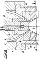
- To the basic structure of the extrusion head include Housing 1, a quill 2, an annular melt channel 3, an annular gap nozzle 4 and acting on the melt channel Adjusting device 5 for changing the melt channel geometry.
- the annular gap nozzle 4 consists of a nozzle upper part 6, through a nozzle retaining ring 7 to the housing 1 is connected, an annular nozzle insert. 8 and an axially movable mandrel 9.
- the nozzle insert 8 and the mandrel 9 define a nozzle gap whose gap width by axial adjusting movements of the mandrel 9 during the extrusion a thermoplastic preform according to a Wanddickenstellprogramm WDS is regulated.
- the adjusting device 5 acts on the melt channel above the nozzle insert 8 3 and performs during the extrusion of the preform of a radial Wanddickenstellprogramm RWDS controlled Stellmony.
- the nozzle insert 8 and / or the mandrel 9, depending on the constructive Embodiment of the device a cross-sectional profile on, which produces thick and thin spots in the melt flow, or are with a flexible cuff 10 to change the nozzle gap geometry provided or with a in the flow area engaging, adjustable profiling device 11 equipped.
- the various constructive Embodiments will be based on the figures below explained in more detail.
- the nozzle insert 8 and the mandrel 9 are as one or more parts without removal of the Nozzle upper part 6 and the adjusting device 5 interchangeable, so that the diameter and the geometry of the annular gap nozzle 4 in the region of the nozzle insert 8 in accordance with the to be manufactured Container cross section can be changed.
- the Figures 8a to 8e show typical cross-sectional shapes of in a blow mold expanded, finished hollow body.
- the preforms have a wall thickness profile have, which the different stretching paths takes account of the expansion in the blow mold, so that the finished hollow body an approximately constant wall thickness has.
- the wall thickness profile of the tubular Preforms depends on the container cross section to be manufactured differently. The setting is after the inventive method and with that shown in the figures Device without conversion of the adjusting device 5 alone by replacing the nozzle inserts 8 and / or the Dorns 9 or by actuating actuators of the nozzle insert or the mandrel, which the geometry of the die gap change, possible.
- nozzle insert 8 acting on the melt channel 3 actuator 5 offers different possibilities.
- the adjusting device a trained as a sleeve 12 slide, the is guided in the sleeve 2 axially movable and a conical End face 13 has.
- the end face 13 of the Slider 12 and / or an opposite conical section the annular gap nozzle is profiled in the circumferential direction. Profiled means that the circumference in the flow direction aligned depressions and elevations, which are thick places and create thin points in the melt flow provided are.
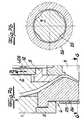
- the slider can also, as shown in Figs. 2a and 2b represented by-pass channels 14, which the Melt distribution on the circumference of the slider 12 influenced.
- FIG. 3a Another embodiment of the above the nozzle insert. 8 is acting on the melt channel 3 actuator 5 shown in Figs. 3a and 3b.
- the adjusting device 5 has guided in this embodiment in the nozzle upper part 6, radially movable slide 15. Depending on the slider position is the deviation of the melt channel cross section from one annular gap more or less pronounced (Fig. 3b).
- the deformable by essentially radial adjusting elements 17 is.
- the adjusting movements of the sleeve 16 acting on Control elements 17 are after the radial Wanddickenstellprogramm RWDS regulated during the hose outlet.
- Extrusion head is the elastically deformable sleeve 16 in Nozzle top 6 is arranged.
- Figures 6a / 6b show one after the radial Wanddickenstellprogramm RWDS controlled adjusting device 5 with a in the nozzle upper part 6 axially movable collar 18 whose conical annular surface 19 a wall portion of the melt channel forms.
- the conical annular surface 19 and / or a opposite conical section of quill 2 is on Perimeter profiled in flow direction.
- the controlled according to the radial Wanddickenstellprogramm RWDS Setting device 5 above the nozzle insert 8 is used for shaping the preform sections after expansion of the preform in the blow mold substantially a container base and a container top of the finished Form hollow body.
- the wall thickness profiling of the preform section, the after expansion in the blow mold a container portion between the container top and Container bottom forms takes place in the region of the nozzle insert 8, preferably in the immediate vicinity of the nozzle outlet.
- the profiling of this preform section is directed according to the container cross-section to be produced and must be adapted be when containers with differently shaped Container cross sections to be produced. The adaptation is possible in different ways.
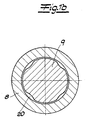
- the mandrel 9 has circumferential, extending in the flow direction Recesses 20, the thick points in the melt flow produce.
- Corresponding profiles can also provided on the conical annular surface of the nozzle insert 8 his.
- the conical surface of the mandrel 9 and / or the conical Surface of the nozzle insert 8 a melt flow forming, with recessed cross-sectional profile, wherein the tread depth decreases to the nozzle outlet, so that with a the nozzle gap width increasing positioning movement WDS of the Dorns 9 and / or the nozzle insert 8 the profiling of Increased nozzle gap and with a die gap width reducing opposing actuating movement of the mandrel 9 or the nozzle insert 8 at the same time the profiling of the Nozzle gap is weakened.
- An appropriate version is shown in Fig. 2a.
- the Fig. 2a takes one, that the profiling of the mandrel 9 a to the nozzle exit decreasing tread depth 21 has. Corresponding designs are also possible on the circumference of the nozzle insert 8.
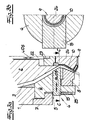
- the mandrel 9 and / or the nozzle insert 8 can also with a flexible sleeve 10 for changing the nozzle gap geometry be provided.
- a flexible sleeve 10 for changing the nozzle gap geometry be provided.
- the mandrel 9 consists of a with a control rod 22 connected mandrel top 23, a elastic end connected to the mandrel upper part 23 deformable cuff 10 and one at the bottom in the sleeve 10 insertable and detachable on the Dornoberteil 23 fortified spreader 24.
- the cuff must be 10 as well the circumferential annular nozzle insert 8 replaced become.
- the nozzle insert 8 has a in this embodiment
- Profiling device 11 from at least one underside arranged adjustably on the circumference of the nozzle gap outlet Element on which in the flow region of the melt intervenes.
- the adjusting devices shown in the figures on the one hand 5 above the nozzle insert 8 and in the figures illustrated measures for influencing the melt distribution Immediately at the nozzle outlet are in arbitrary Way combined with each other.
- the figures are taken from Furthermore, that the nozzle insert 8 in one or more parts can be trained.
- the nozzle insert 8 In a multi-part design the nozzle insert 8 consists of two or more superimposed Rings.
- the individual components are part a set of elements and can be made in accordance with the Containers are combined with each other.
- the annular gap nozzle 4 a nozzle top part 6 and a replaceable nozzle insert 8.
- the adjusting device 5 is above the annular gap 4 arranged in the housing 1.
- the nozzle body 26 and the mandrel 9 are interchangeable. They show how previously described using the example of the nozzle insert and the mandrel, a thick and thin spots in the melt flow generating Cross-sectional profile on or are flexible Cuff provided for changing the nozzle gap geometry or are with an intervening in the flow area, equipped adjustable profiling device.
- the inventive device and the invention Methods are characterized by considerable advantages. she enable the production of blow-molded plastic containers with different container cross-sections and a given in tight tolerances wall thickness.
- the necessary Conversions are limited to an exchange the nozzle body or the nozzle insert and / or of the nozzle mandrel or on adjustments to actuators of Nozzle body or the nozzle insert or the mandrel, which change the geometry of the nozzle gap. Short change times are feasible. In the preferred embodiment even the outside heating 25, as in the figures shown, remain on the extrusion head. If the Nozzle outlet only with respect to the nozzle diameter must be changed, it is advisable, the nozzle insert as well as the spike shown by dashed lines in the figures Change adapter plates. The adaptation parts or replacement parts are screwed on or can if necessary also be attached with a quick-change system.
Landscapes
- Engineering & Computer Science (AREA)
- Mechanical Engineering (AREA)
- Manufacturing & Machinery (AREA)
- Blow-Moulding Or Thermoforming Of Plastics Or The Like (AREA)
Description
- Fig. 1a
- den Längsschnitt durch einen Strangpreßkopf,
- Fig. 1b
- einen Querschnitt durch die in Fig. 1 dargestellte Vorrichtung in der Schnittebene A-A,
- Fig. 2a bis 7a
- weitere Ausführungen der erfindungsgemäßen Vorrichtung, jeweils in einem hälftigen Längsschnitt,
- Fig. 2b bis 7b
- Querschnitte durch die in den Fig.2a bis 7a dargestellten Vorrichtungen in den angegebenen Schnittebenen,
- Fig. 8a bis 8e
- typische Querschnittsformen der unter Verwendung der in den Figuren dargestellten Vorrichtungen durch Extrusionsblasformen herstellbaren Kunststoffbehälter.
Claims (12)
- Verfahren zum Extrusionsblasformen von Kunststoffbehältern mit unterschiedlichen Behälterquerschnitten, bei dem ein schlauchförmiger Vorformling aus einer thermoplastischen Kunststoffschmelze aus einem Strangpreßkopf, der einen ringförmigen Schmelzekanal und eine Ringspaltdüse mit verstellbarer Düsenspaltbreite aufweist, extrudiert und in einer Blasform zu einem Kunststoffbehälter aufgeweitet wird,
wobei die Düsenspaltbreite durch axiale Stellbewegungen eines Düsenkörpers oder eines Düseneinsatzes und/oder eines Dorns nach einem Wanddickenstellprogramm (WDS) während des Schlauchaustritts geregelt wird und
wobei die Schmelzeverteilung in Umfangsrichtung durch eine zusätzliche, auf den Schmelzekanal einwirkende Stelleinrichtung nach einem radialen Wanddickenstellprogramm (RWDS) geregelt wird,
dadurch gekennzeichnet, daß im wesentlichen nur die endseitigen Abschnitte des Vorformlings, die in der Blasform zu einem Behälteroberteil und Behälterunterteil aufgeweitet werden, nach dem radialen Wanddickenstellprogramm (RWDS) durch Stellbewegungen der Stelleinrichtung geformt werden, wobei die Stelleinrichtung oberhalb der Ringspaltdüse oder oberhalb eines austauschbaren Düseneinsatzes der Ringspaltdüse auf den Schmelzkanal einwirkt und in einer für verschiedene Größen und Formen des Behälterquerschnitts unveränderten Ausführung verwendet wird, und daß der Durchmesser und/oder die Geometrie des Düsenspaltes nach Maßgabe des zu fertigenden Behälterquerschnitts verändert wird, indem die Ringspaltdüse oder der Düseneinsatz und/oder der Dorn ausgetauscht oder Einstellungen an zusätzlichen, am Düsenaustritt oder düsenaustrittsnah angeordneten Stellelementen vorgenommen werden. - Strangpreßkopf zur Durchführung des Verfahrens nach Anspruch 1 mitwobei der Düseneinsatz (8) und der Dorn (9) einen Düsenspalt begrenzen, dessen Spaltbreite durch axiale Stellbewegungen des Düseneinsatzes (8) und/oder des Dorns (9) während der Extrusion eines thermoplastischen Vorformlings nach einem Wanddickenstellprogramm (WDS) regelbar ist und wobei die Stelleinrichtung (5) während der Extrusion des Vorformlings von einem radialen Wanddickenstellprogramm (RWDS) gesteuerte Stellbewegungen ausführt, dadurch gekennzeichnet, daß die Stelleinrichtung (5) oberhalb des Düseneinsatzes (8) auf den Schmelzekanal (3) einwirkt, daß der Düseneinsatz (8) und/oder der Dorn (9) ein Dick- und Dünnstellen im Schmelzefluß erzeugendes Querschnittsprofil aufweist oder mit einer flexiblen Manschette (10) zur Veränderung der Düsenspaltgeometrie versehen ist oder mit einer in den Fließbereich eingreifenden, verstellbaren Profilierungseinrichtung (11) ausgerüstet ist und daß der Düseneinsatz (8) und der Dorn (9) als ein- oder mehrteilige Bauteile ohne Ausbau des Düsenoberteils (6) und der Stelleinrichtung (5) auswechselbar sind.Gehäuse (1),Pinole (2),einem ringförmigen Schmelzekanal (3),einer Ringspaltdüse (4), die ein an das Gehäuse (1) angeschlossenes Düsenoberteil (6), einen ringförmigen Düseneinsatz (8) sowie einen Dorn (9) aufweist, undeiner auf den Schmelzekanal (13) einwirkenden Stelleinrichtung (5) zur Veränderung der Schmelzekanalgeometrie,
- Strangpreßkopf zur Durchführung des Verfahrens nach Anspruch 1 mitwobei der Düsenkörper (26) und der Dorn (9) einen Düsenspalt begrenzen, dessen Spaltbreite durch axiale Stellbewegungen des Düsenkörpers (26) und/oder des Dorns (9) während der Extrusion eines thermoplastischen Vorformlings nach einem Wanddickenstellprogramm (WDS)regelbar ist und wobei die Stelleinrichtung (5) während der Extrusion des Vorformlings von einem radialen Wanddickenstellprogramm (RWDS) gesteuerte Stellbewegung ausführt, dadurch gekennzeichnet, daß die Stelleinrichtung (5) oberhalb der Ringspaltdüse (4) auf den Schmelzekanal (3) einwirkt, daß der Düsenkörper (26) und/oder der Dorn (9) ein Dick- und Dünnstellen im Schmelzefluß erzeugendes Querschnittsprofil aufweist oder mit einer flexiblen Manschette (10) zur Veränderung der Düsenspaltgeometrie versehen ist oder mit einer in den Fließbereich eingreifenden, verstellbaren Profilierungseinrichtung (11) ausgerüstet ist und daß der Düsenkörper (26) und der Dorn (9) ohne Ausbau der Stelleinrichtung (5) auswechselbar sind.Gehäuse (1),Pinole (2),einem ringförmigen Schmelzekanal (3),einer Ringspaltdüse (4), die einen einteiligen Düsenkörper (26) sowie einen Dorn (9) aufweist, undeine auf den Schmelzekanal (13) einwirkenden Stelleinrichtung (15) zur Veränderung der Schmelzekanalgeometrie,
- Strangpreßkopf nach Anspruch 2 oder 3, dadurch gekennzeichnet, daß die oberhalb des Düseneinsatzes (8) oder des Düsenkörpers (26) auf den Schmelzekanal (3) einwirkende Stelleinrichtung (5) einen als Hülse ausgebildeten Schieber (12) aufweist, der in der Pinole (2) axial beweglich geführt ist und eine kegelförmige Stirnfläche (13) aufweist, wobei die Stirnfläche (13) des Schiebers (12) und/oder ein gegenüberliegender konischer Abschnitt der Ringspaltdüse in Umfangsrichtung profiliert ist.
- Strangpreßkopf nach Anspruch 4, dadurch gekennzeichnet, daß der Schieber (12) By-Pass-Kanäle aufweist.
- Strangpreßkopf nach Anspruch 2 oder 3, dadurch gekennzeichnet, daß die Stelleinrichtung (5) einen im Düsenoberteil (6) oder im Gehäuse (1) axial beweglichen Stellring (18) aufweist, dessen konische Ringfläche (19) einen Wandabschnitt des Schmelzekanals bildet, wobei die konische Ringfläche (19) und/oder ein gegenüberliegender konischer Abschnitt der Pinole (2) in Umfangsrichtung profiliert ist.
- Strangpreßkopf nach Anspruch 2 oder 3, dadurch gekennzeichnet, daß die auf den Schmelzekanal (3) einwirkende Stelleinrichtung (5) im Düsenoberteil (6) oder im Gehäuse (1) geführte, radial bewegliche Schieber (15) aufweist.
- Strangpreßkopf nach Anspruch 2 oder 3, dadurch gekennzeichnet, daß die oberhalb des Düseneinsatzes (8) oder oberhalb des Düsenkörpers (26) auf den Schmelzekanal (3) einwirkende Stelleinrichtung (5) eine den Schmelzekanal begrenzende elastische Hülse (16) aufweist, die über im wesentlichen radiale Stellelemente (17) verformbar ist.
- Strangpreßkopf nach einem der Ansprüche 2 bis 8, dadurch gekennzeichnet, daß die kegelförmige Mantelfläche des Dorns (9) und/oder die konische Fläche des Düseneinsatzes (8) bzw. des Düsenkörpers (26) ein den Schmelzefluß formendes, mit Vertiefungen versehenes Querschnittsprofil aufweist, wobei die Profiltiefe (21) zum Düsenaustritt abnimmt, so daß mit einer die Düsenspaltbreite vergrößernden Stellbewegung (WDS) des Dorns (9) und/oder des Düseneinsatzes (8) bzw. des Düsenkörpers (26) die Profilierung des Düsenspaltes verstärkt und mit einer die Düsenspaltbreite reduzierenden entgegengesetzten Stellbewegung des Dorns oder des Düseneinsatzes bzw. des Düsenkörpers zugleich die Profilierung des Düsenspaltes abgeschwächt wird.
- Strangpreßkopf nach einem der Ansprüche 2 bis 8, dadurch gekennzeichnet, daß der Dorn (9) aus einem mit einer Stellstange (22) verbundenen Dornoberteil (23), einer endseitig an das Dornoberteil (23) angeschlossenen elastisch verformbaren Manschette (10) sowie einem an der Unterseite in die Manschette (10) einführbaren sowie lösbar am Dornoberteil (6) befestigten Spreizkörper (24) besteht.
- Strangpreßkopf nach einem der Ansprüche 2 bis 8, dadurch gekennzeichnet, daß der Düseneinsatz (8), des Düsenkörpers und/oder der Dorn (9) eine Profilierungseinrichtung (11) aus mindestens einem unterseitig am Umfang des Düsenspaltaustritts verstellbar angeordneten Element aufweist, welches in den Fließbereich eingreift.
- Strangpreßkopf nach einem der Ansprüche 2 bis 8, dadurch gekennzeichnet, daß der Düseneinsatz (8) aus mindestens zwei stirnseitig aufeinanderliegenden Ringen zusammengesetzt ist.
Applications Claiming Priority (2)
| Application Number | Priority Date | Filing Date | Title |
|---|---|---|---|
| DE19854249 | 1998-11-24 | ||
| DE19854249A DE19854249C2 (de) | 1998-11-24 | 1998-11-24 | Verfahren und Vorrichtung zum Extrusionsblasformen von Kunststoffbehältern mit unterschiedlichen Behälterquerschnitten |
Publications (2)
| Publication Number | Publication Date |
|---|---|
| EP1004423A1 EP1004423A1 (de) | 2000-05-31 |
| EP1004423B1 true EP1004423B1 (de) | 2003-03-26 |
Family
ID=7888888
Family Applications (1)
| Application Number | Title | Priority Date | Filing Date |
|---|---|---|---|
| EP99122998A Expired - Lifetime EP1004423B1 (de) | 1998-11-24 | 1999-11-19 | Verfahren und Vorrichtung zum Extensionsblasformen von Kunststoffbehältern mit unterschiedlichen Behälterquerschnitten |
Country Status (3)
| Country | Link |
|---|---|
| EP (1) | EP1004423B1 (de) |
| AT (1) | ATE235364T1 (de) |
| DE (2) | DE19854249C2 (de) |
Families Citing this family (14)
| Publication number | Priority date | Publication date | Assignee | Title |
|---|---|---|---|---|
| DE19903084C2 (de) * | 1999-01-27 | 2001-01-25 | Harald Feuerherm | Strangpreßkopf zum Extrusionsblasformen von Kunststoffbehältern |
| RU2185286C1 (ru) * | 2001-10-26 | 2002-07-20 | Государственное образовательное учреждение Воронежская государственная технологическая академия | Формующее устройство экструдера |
| ES2303942T3 (es) | 2003-03-28 | 2008-09-01 | Harald Feuerherm | Procedimiento para el moldeo por soplado de cuerpos huecos de material sintetico termoplastico. |
| ITMI20050110A1 (it) * | 2005-01-27 | 2006-07-28 | Uniloy Milacron S R L | Tsta di estrusione per il soffiaggio di corpi cavi con sistema di distribuzione dello spessore delle pareti del parison |
| RU2411123C2 (ru) * | 2006-07-25 | 2011-02-10 | Юнилой Милакрон С.Р.Л. | Экструзионная головка для выдувного формования полых тел с системой распределения толщины стенок заготовки |
| JP4857380B2 (ja) * | 2006-07-25 | 2012-01-18 | ユニロイ ミラクロン ソシエタ レスポンサビリタ リミタータ | パリソンの壁の厚さの分布のシステムを有する、中空体のブロー成形用の押し出しヘッド |
| DE102012013381B4 (de) * | 2012-07-01 | 2021-07-15 | Maik Hentschel | Verstellbare Extrusionsdüse zum Extrudieren von schlauchförmigen Kunststoff-Vorformlingen unterschiedlichen Querschnitts |
| DE102012108374A1 (de) * | 2012-09-07 | 2014-03-13 | Harald Feuerherm | Verfahren zur Herstellung blasgeformter Kunststoffhohlkörper und Mehrfachextrusionskopf zur Durchführung des Verfahrens |
| DE102013109495B3 (de) * | 2013-08-30 | 2014-08-14 | Harald Feuerherm | Extrusionswerkzeug zur Erzeugung schlauchförmiger Vorformlinge |
| CN107553876B (zh) * | 2017-07-20 | 2019-08-13 | 南通大学 | 一种用于生产立方体容器的吹塑机及其工作方法 |
| CN109910271A (zh) * | 2019-03-12 | 2019-06-21 | 张家港考克机械有限公司 | 吹塑机中能够调节管坯径向壁厚的型坯模具 |
| DE202019105683U1 (de) * | 2019-10-15 | 2021-01-19 | Kautex Maschinenbau Gmbh | Extrusionstechnik zur Bildung von Kunststoff-Vorformlingen und Profilierungstechnik |
| DE102021119460B3 (de) * | 2021-07-27 | 2022-09-08 | Max Feuerherm | Düsenwerkzeugsystem und Extrusionsblasanordnung |
| CN118990990B (zh) * | 2024-10-24 | 2024-12-27 | 太湖方舟新材料科技有限公司 | 一种双拉聚酰亚胺薄膜的成型装置及方法 |
Family Cites Families (2)
| Publication number | Priority date | Publication date | Assignee | Title |
|---|---|---|---|---|
| GB1004332A (en) * | 1961-02-25 | 1965-09-15 | Blow O Matic Corp Ltd | Extrusion head, a method of extruding and apparatus for utilising the method |
| IT1243421B (it) * | 1990-09-25 | 1994-06-10 | Soffiaggio Tecnica Srl | Dispositivo per controllare lo spessore radiale di estrusione di polimeri termoplastici. |
-
1998
- 1998-11-24 DE DE19854249A patent/DE19854249C2/de not_active Expired - Fee Related
-
1999
- 1999-11-19 DE DE59904713T patent/DE59904713D1/de not_active Expired - Lifetime
- 1999-11-19 EP EP99122998A patent/EP1004423B1/de not_active Expired - Lifetime
- 1999-11-19 AT AT99122998T patent/ATE235364T1/de active
Also Published As
| Publication number | Publication date |
|---|---|
| DE19854249A1 (de) | 2000-05-31 |
| DE59904713D1 (de) | 2003-04-30 |
| DE19854249C2 (de) | 2001-01-25 |
| ATE235364T1 (de) | 2003-04-15 |
| EP1004423A1 (de) | 2000-05-31 |
Similar Documents
| Publication | Publication Date | Title |
|---|---|---|
| EP0945245B1 (de) | Verfahren zum Extrusionsblasverfahren von Hohlkörpern | |
| DE19903084C2 (de) | Strangpreßkopf zum Extrusionsblasformen von Kunststoffbehältern | |
| DE19854249C2 (de) | Verfahren und Vorrichtung zum Extrusionsblasformen von Kunststoffbehältern mit unterschiedlichen Behälterquerschnitten | |
| DE102012004166B4 (de) | Ringspaltdüse sowie Verfahren zur Extrusion | |
| EP0311875A2 (de) | Verfahren und Vorrichtung zur Herstellung von Mehrschicht-Formteilen | |
| DE1233571B (de) | Verfahren und Vorrichtung zum Durchfuehren plastischen Materials von einer Plastifiziereinrichtung durch einen Durchflusskopf zu einer Duese zum Auspressen eines Stranges, insbesondere zum Herstellen eines Hohlkoerpers aus thermoplastischem Kunststoff nach dem Blasverfahren | |
| EP2148773B1 (de) | Vorrichtung und verfahren zur herstellung von kunststoffgegenständen durch extrusionsblasformen | |
| CH628567A5 (de) | Vorrichtung zur herstellung eines kunststoff-hohlkoerpers. | |
| EP1837156A2 (de) | Extrusionsverfahren für schlauchförmige Vorformlingen | |
| DE202019105683U1 (de) | Extrusionstechnik zur Bildung von Kunststoff-Vorformlingen und Profilierungstechnik | |
| EP1687127B1 (de) | Formnestaufbau | |
| EP2155468A1 (de) | Extrusionsblasformmaschine sowie verfahren zur herstellung eines kunststoffhohlkörpers | |
| DE2703454A1 (de) | Verfahren und vorrichtung zum blasformen | |
| EP1063074B1 (de) | Verfahren zum Einrichten einer Ringspaltdüse zur Herstellung von schlauchförmigen Vorformlingen | |
| DE202006013751U1 (de) | Vorrichtung zur Herstellung von bandförmigen Kunststoffvorformlingen | |
| EP1610939B1 (de) | Verfahren zum blasformen von hohlkorpern aus thermoplastischem kunststoff | |
| DE102006042065A1 (de) | Verfahren und Vorrichtung zur Herstellung von bandförmigen Kunststoffvorformlingen | |
| DE2202200A1 (de) | Press- und Spritzmaschine und Verfahren zur Herstellung von Formteilen | |
| DE102006004928A1 (de) | Verbesserte Halsbackenkühlung | |
| DE69623136T2 (de) | Formkühlvorrichtung für die glasindustrie und verfahren zum herstellen und anpassen dieser kühlvorrichtung an verschiedenen formen | |
| DE19603231C1 (de) | Extrusionskopf für das Blasformen von Hohlkörpern aus thermoplastischem Kunststoff | |
| DE19904199C2 (de) | Strangpreßkopf zum Extrusionsblasformen von Kunststoffbehältern | |
| EP0599078B1 (de) | Verfahren und Blasformstation zur Herstellung eines Hohlkörpers mit einer Öffnung im Bodenbereich | |
| DE19829183A1 (de) | Vorrichtung zur Trennung beweglicher Einsätze und Bauteile von mit thermoplastischen Kunststoffen durchströmten Fließkanälen | |
| DE8801851U1 (de) | Vorrichtung zur Herstellung von Preßkörpern aus thermoplastischem Kunststoffmaterial |
Legal Events
| Date | Code | Title | Description |
|---|---|---|---|
| PUAI | Public reference made under article 153(3) epc to a published international application that has entered the european phase |
Free format text: ORIGINAL CODE: 0009012 |
|
| AK | Designated contracting states |
Kind code of ref document: A1 Designated state(s): AT DE FR IT |
|
| AX | Request for extension of the european patent |
Free format text: AL;LT;LV;MK;RO;SI |
|
| 17P | Request for examination filed |
Effective date: 20001111 |
|
| AKX | Designation fees paid |
Free format text: AT DE FR IT |
|
| 17Q | First examination report despatched |
Effective date: 20010803 |
|
| GRAH | Despatch of communication of intention to grant a patent |
Free format text: ORIGINAL CODE: EPIDOS IGRA |
|
| GRAH | Despatch of communication of intention to grant a patent |
Free format text: ORIGINAL CODE: EPIDOS IGRA |
|
| GRAA | (expected) grant |
Free format text: ORIGINAL CODE: 0009210 |
|
| AK | Designated contracting states |
Designated state(s): AT DE FR IT |
|
| REF | Corresponds to: |
Ref document number: 59904713 Country of ref document: DE Date of ref document: 20030430 Kind code of ref document: P |
|
| ET | Fr: translation filed | ||
| PLBE | No opposition filed within time limit |
Free format text: ORIGINAL CODE: 0009261 |
|
| STAA | Information on the status of an ep patent application or granted ep patent |
Free format text: STATUS: NO OPPOSITION FILED WITHIN TIME LIMIT |
|
| 26N | No opposition filed |
Effective date: 20031230 |
|
| REG | Reference to a national code |
Ref country code: FR Ref legal event code: PLFP Year of fee payment: 17 |
|
| REG | Reference to a national code |
Ref country code: FR Ref legal event code: PLFP Year of fee payment: 18 |
|
| REG | Reference to a national code |
Ref country code: FR Ref legal event code: PLFP Year of fee payment: 19 |
|
| REG | Reference to a national code |
Ref country code: DE Ref legal event code: R079 Ref document number: 59904713 Country of ref document: DE Free format text: PREVIOUS MAIN CLASS: B29C0047220000 Ipc: B29C0048325000 |
|
| PGFP | Annual fee paid to national office [announced via postgrant information from national office to epo] |
Ref country code: DE Payment date: 20181126 Year of fee payment: 20 Ref country code: AT Payment date: 20181121 Year of fee payment: 20 |
|
| PGFP | Annual fee paid to national office [announced via postgrant information from national office to epo] |
Ref country code: FR Payment date: 20181123 Year of fee payment: 20 Ref country code: IT Payment date: 20181126 Year of fee payment: 20 |
|
| REG | Reference to a national code |
Ref country code: DE Ref legal event code: R071 Ref document number: 59904713 Country of ref document: DE |
|
| REG | Reference to a national code |
Ref country code: AT Ref legal event code: MK07 Ref document number: 235364 Country of ref document: AT Kind code of ref document: T Effective date: 20191119 |