EP1004512B1 - Verfahren und Vorrichtung zum Aufrollen und Binden,mittels eines Kunststoffbindestreifens, von aufgerollten Strängen von Längen drahtförmiger Elemente, wie Kabel, Seile und dergleichen, insbesondere Netzkabel - Google Patents
Verfahren und Vorrichtung zum Aufrollen und Binden,mittels eines Kunststoffbindestreifens, von aufgerollten Strängen von Längen drahtförmiger Elemente, wie Kabel, Seile und dergleichen, insbesondere Netzkabel Download PDFInfo
- Publication number
- EP1004512B1 EP1004512B1 EP99122744A EP99122744A EP1004512B1 EP 1004512 B1 EP1004512 B1 EP 1004512B1 EP 99122744 A EP99122744 A EP 99122744A EP 99122744 A EP99122744 A EP 99122744A EP 1004512 B1 EP1004512 B1 EP 1004512B1
- Authority
- EP
- European Patent Office
- Prior art keywords
- skein
- tape
- winding
- binding
- length
- Prior art date
- Legal status (The legal status is an assumption and is not a legal conclusion. Google has not performed a legal analysis and makes no representation as to the accuracy of the status listed.)
- Expired - Lifetime
Links
- 238000000034 method Methods 0.000 title claims abstract description 16
- 238000004804 winding Methods 0.000 title claims abstract description 14
- 239000002985 plastic film Substances 0.000 title description 2
- 229920006255 plastic film Polymers 0.000 title description 2
- 239000000463 material Substances 0.000 claims abstract description 10
- 239000004033 plastic Substances 0.000 claims abstract description 7
- 238000003466 welding Methods 0.000 claims description 11
- 238000005520 cutting process Methods 0.000 claims description 6
- 230000008878 coupling Effects 0.000 claims description 4
- 238000010168 coupling process Methods 0.000 claims description 4
- 238000005859 coupling reaction Methods 0.000 claims description 4
- 238000011084 recovery Methods 0.000 claims description 3
- 238000000151 deposition Methods 0.000 claims description 2
- 230000000694 effects Effects 0.000 claims 1
- 239000010410 layer Substances 0.000 claims 1
- 239000002356 single layer Substances 0.000 claims 1
- 230000000295 complement effect Effects 0.000 abstract description 2
- 238000004519 manufacturing process Methods 0.000 description 4
- 230000015572 biosynthetic process Effects 0.000 description 2
- 238000005259 measurement Methods 0.000 description 2
- 230000013011 mating Effects 0.000 description 1
- 239000002184 metal Substances 0.000 description 1
- 238000004806 packaging method and process Methods 0.000 description 1
Images



Classifications
-
- B—PERFORMING OPERATIONS; TRANSPORTING
- B65—CONVEYING; PACKING; STORING; HANDLING THIN OR FILAMENTARY MATERIAL
- B65B—MACHINES, APPARATUS OR DEVICES FOR, OR METHODS OF, PACKAGING ARTICLES OR MATERIALS; UNPACKING
- B65B63/00—Auxiliary devices, not otherwise provided for, for operating on articles or materials to be packaged
- B65B63/04—Auxiliary devices, not otherwise provided for, for operating on articles or materials to be packaged for folding or winding articles, e.g. gloves or stockings
- B65B63/06—Forming elongated hanks, e.g. of shoe laces
Definitions
- the present invention relates to a process for winding up and binding, by means of a tape of plastic film, lengths of filiform elements, such as cables, ropes and the like, in particular mains cords, wound in the form of skeins, and a winding and binding machine for implementing such process.
- said electric cables are demanded in the form of skeins tied together by means of a binding element, one end of which electric cable, already provided with a user mains coupling plug, projecting from the skein, while the other end of said electric cable, it too projecting from the skein, has the two phase wires and the earth wire ready for connection to the appliance.
- the coupling cable can be connected to the electric appliance prior to its packaging, and the installer or user must merely free the skein of its binding element for switching on the appliance.
- the object of the present invention is to overcome the above mentioned drawbacks, by contemplating the use of a machine designed for automatically performing the required operating steps, with a high production yield, thereby allowing few machines to meet a large production volume, saving on labour and performing the binding of the lengths skein using only a tape of thermo-weldable, metal-core-free plastic material which does not cause the cited drawbacks.
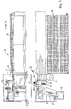
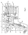
- Figures 1 and 2 schematically show, in a top plan view and a front elevation view, respectively, the winding-up and binding machine according to the instant invention.
- This machine generally indicated by reference numeral 1, has, as seen in a top plan view, an angled, very compact shape, and it is provided with two working stations 4 and 6 which perform, in series, two different, mutually complementary operations so that, while the second station 6 completes the process of the first, the first station 4 is ready to start a subsequent winding-up operation, with an evident advantage with regard to the rapidity of performing the entire process.
- an operator A who avails himself of a control keyboard T to start or stop the machine or one of its parts, will simply feed, on a conveyor belt 2, consisting of articulated elements, the lengths 3 with their end 31 provided with a plug facing the left of the operator.
- the lengths can be fed in any desired manner or they can be collected from an auxiliary rack R not pertaining to the invention.
- the lengths 3, arranged on the conveyor belt 2, are brought to the working station 4, which will be described thereinafter, to perform the winding-up of the skein, while, in the second working station 6, arranged obliquely on one side of the operator A, the length skein will be bound by a binding tape and ejected into the container 9.
- Figures 3, 4A and 4B show the skeins being formed at the working station 4.
- the lengths 3 are arranged by the operator A on the articulated element conveyor belt 2, with the length portion, provided with the plug 31, clamped between a resilient fork 32 and a pair of rollers 33.
- each length 3 deposited on the conveyor belt 2 is grasped by a clamp group 40, slidingly supported on a rail 41, and driven to the position 34, shown by a dashed line, in alignment with the skein winding center 42.
- the winding-up of the length is carried out between two pins 43, which can be manually fixed, at a preset distance, on a cross-member 44, coupled to a rotary shaft 45, which member can be vertically driven by a piston 46 and made to rotate by a sleeve 47 in turn driven by a motor 48.
- the winding-up of the skein about the pins 43 offers various advantages, namely i) the possibility of changing the diameter of the skein in a range much broader than that of the winding apparatus known in the art, and ii) that, after having performed the winding, the disengagement of the skein for it to be subsequently taken for binding, is achieved by lowering the pins 43 so as to leave the skein in a compact condition and with its coils orderly arranged.
- the winding-up is started after the clamp group 40, sliding on rail 41, advances by a distance L which can be preset depending on the positions of the pins 43, in order to automatically and uniformly define, for one and the same batch of lengths being worked, the projection of the starting portion from the finished skein on the basis of the distance between the end point of the clamp group 40 stroke and the nearest pins 43.
- the length 3 is clamped and locked onto the winding-up mandrel by means of a pair of clamping means 49, 49', driven by the pistons 50, 50' and turning together with the winding mandrel, in order to obtain a perfectly wound-up skein.
- a deviating arm 51 pivoted at 52 is shown, said arm being driven by a small piston 53, which arm, immediately after having released the length 3, grasped by the clamp group 40, deviates, when the pins 43 start to turn anticlockwise, the length portion projecting from the skein into a basket 54 turning together with said pins 43, in order to prevent said length portion from being centrifugally ejected during the winding-up operation, the skein being formed with evenly overlapping coils, since the length being wound up is guided by a pair of small rollers 55 which have facing concave surfaces and which are gradually displaced upwardly in synchronism with the turning of the pins 43.
- the second tape binding station 6 comes into action, the operating time of which is coordinated with that of the winding-up station 4 so that in said station 4 can be started the formation of a new skein, while the previously prepared skein is being bound.
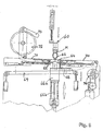
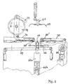
- FIGS 5, 6, 7 show the arrangement of the main elements of the tape binding station 6.
- a clamp group 60 slidingly supported on the rail 61 ( Figure 3), engages with its arms 62 the middle portion of the wound-up skein M and goes back until it is above the recess 64.
- Figure 5 shws that above the recess 64 is transversely arranged a tape of a plastic material 70 delivered from a tape bobbin 72, braked by an arm 73, said tape being fed and held in a stretched condition by a recovery assembly 74.
- the skein M carried by the clamp 60, is now grasped at its two end portions by a pair of side clamps 66, 66', it is released by the clamp 60 ( Figure 6) upon the opening of the arms 62 and it is lowered against the tape 70 which envelops the skein for more than half its cross extension.
- the clamp 60 In order to maintain the skein in a compacted condition, it is made to bear against a flexible tongue 67, arranged on a slider 68, sliding on a rod-free piston 69.
- the side clamps 66, 66', coupled to a common base 66a which can be vertically driven by a piston 66b, are shown in Figure 5 in a raised position and in Figure 6 in a lowered position.
- FIG 7 substantially shows the final step of the winding-up and tape binding process.
- two pairs of heated heads 80, 80' are neared one to the other and they perform simultaneously two neighbouring welding operations on the plastic tape, which will then immediately be cut by a blade 82 situated between the welding heads 80, 80', so that the binding tape 84 (see Figure 8) is welded together, while maintaining the wound-up skein in a well compacted condition, while the second welding of the tape 70 will keep it continuous, which tape can be made to advance by the recovering assembly 74, thereby presenting a fresh portion of tape 70 for binding a subsequent skein.
- the process and machine for implementing said process can be used for winding-up and binding any type of filiform elements, such as mains cords lengths ending with plugs and mating sockets or without these elements, telephone cables or cables for other use, ropes for any applications, and the like.
Landscapes
- Engineering & Computer Science (AREA)
- Mechanical Engineering (AREA)
- Basic Packing Technique (AREA)
- Package Frames And Binding Bands (AREA)
- Wire Processing (AREA)
- Ropes Or Cables (AREA)
- Metal Rolling (AREA)
Claims (9)
- Verfahren um Abschnitte fadenförmiger Elemente wie etwa Kabel, Seile und dergleichen, insbesondere aber elektrische, wahlweise mit einem Stecker versehene Anschlusskabel, aufzuwickeln und zu binden, gekennzeichnet durch folgende Schritte:a) Ablegen der Abschnitte auf einen beweglichen Rost;b) Schrittweiser, durch eine Photozelle gesteuerter Transfer der Abschnitte zu einer Aufnahmestelle;c) Fassen und Anheben jedes Abschnittes mittels einer beweglichen Zange;d) Anordnen des Abschnittes in einer Aufwickelzone, wobei berücksichtigt wird, dass ein wählbarer Teil des fadenförmigen Elementes aus dem Strang herausragen kann wenn dieser einmal aufgewickelt und in seiner Mitte gebunden ist;e) Halten des Abschnittes auf einem Dorn und Beginn des Wickelprozesses nachdem jener wählbare, aus dem Strang ragende Teil in einem rotierenden Korb eingelegt wurde, und Bildung eines Stranges;f) Fassen des Stranges in seinem mittleren Teil durch eine Transportzange, nachdem die Wickelelemente abwärts entfernt wurden;g) Transfer des Stranges zum Eingang einer Bindestation, über welchem ein thermo-schweissbares Band läuft;h) Einführen des Stranges in zwei seitliche Zangen und Öffnen der Backen an Transportzange;i) Herablassen des Stranges mittels der seitlichen Zangen, und Annähern an ein Band aus thermoschweissbarem, fallweise durch Wärme schrumpfbares Material;j) Binden des Stranges durch eine einzige Lage des Bandesk) Schweissen des Bandes durch zwei Paare von einander entsprechenden thermo-schweissenden Zangen, um an zwei benachbarten, aber getrennten Stellen zwei geschweisste Teile zu bilden;l) Durchschneiden des Bandes zwischen den benachbarten, geschweissten Teilen, um den Zusammenhang des Bandes zu erhalten, und entnehmen des zusammengebundenen Bandes ;m) Zurückgewinnung eines Teiles des Bandes unter gleichzeitiger Öffnung der seitlichen Zangen, und Auswerfen des durch das Band gebundenen Stranges in einen Behälter.
- Apparat, um Stränge aus Abschnitten fadenförmiger Elemente wie etwa Kabel, Seile und dergleichen, insbesondere aber mit einem Stecken versehene elektrische Netz-Anschlusskabel aufzuwickeln und in ihrem mittleren Teil zu binden, dadurch gekennzeichnet, dass der Apparat folgende Teile aufweist:a) ein beweglicher Rost (2) auf welchem gestreckte Abschnitte (3) abgelegt werden um sie Stück für Stück dem darauffolgenden, durch eine Photozelle gesteuerten Greifprozess zuzuführen;b) Mittel, um jeden fadenförmigen Abschnitt (3) zu greifen und zu positionieren, wobei diese Mittel eine bewegliche Zangengruppe (40) umfassen die sich bis zu einem in maximalen Abstand von der Aufwickelzone (4) befindlichen Endpunkt bewegen kann, oder möglicherweise über eine grössere Entfernung die der Länge eines wählbaren fadenförmigen Abschnittes entspricht, welcher aus dem fertigen Strang herausragen soll;c) eine Aufwickeleinheit (43) mit Mitteln (49, 49') um besagten Abschnitt zu fassen, und mit einem Korb (54) um den fallweise herausragenden Abschnitt wählbarer Länge aufzunehmen;d) eine Zangengruppe (60) um den Strang in seinem mittleren Teil zu fassen nachdem die Wickelelemente abwärts entfernt wurden, und um den Strang einer Bindestation zuzuführen, wo er mit einem Durchgang (64) fluchtet oberhalb welchem ein aus thermoschweissbarem Material bestehendes Band (70) durchläuft;e) Mittel, um die Enden eines Stranges aufzunehmen, welche Mittel zwei seitliche Zangen (66, 66') umfassen, und um danach die Backen der Fass- und Transfer-Gruppe (60) zu öffnen;f) Mittel (66a, 66b), um die den Strang haltenden seitlichen Zangen (66, 66') auf ein aus thermoschweissbarem, fallweise durch Wärme schrumpfbares Material bestehendes Band (7) herabzulassen, dergestalt, dass das Band eine einzelne, den Strang zusammenbindende Schicht bildet;g) Mittel, um das Band (70) zu schweissen, bestehend aus zwei Paaren von einander entsprechenden Schweissköpfen (80, 80'), um an zwei benachbarten, aber voneinander getrennten, Stellen gleichzeitig zwei geschweisste Stellen zu bilden;h) Schneidemittel (82), um das Band zwischen jenen geschweissten Stellen durchzuschneiden;i) Rückgewinnungsmittel (74), um gleichzeitig mit dem Öffnen der seitlichen Zangen einen Teil des Bandes zurückzugewinnen; undj) Auswurfmittel (68, 69), um den durch ein Band gebundenen Strang in einen Behälter zu befördern.
- Apparat nach Anspruch 2, dadurch gekennzeichnet, dass die Zangengruppe (40) über eine voreinstellbare Strecke (L) auf einer Schiene (41) gleitet, in Abhängigkeit der Länge eines möglichen Anfangsstückes des aus dem Strang herausragenden, fadenförmigen Abschnittes (3), wobei dieser Abschnitt (3) auf einem Pfad liegt, der durch die Mittelachse (42) der Wickeleinheit geht.
- Apparat nach den Ansprüchen 2 und 3, dadurch gekennzeichnet, dass die Wickeleinheit ein Paar vertikaler, zur Drehachse (42) symmetrischer Stifte (43) aufweist, deren Abstand in Abhängigkeit der Länge der fadenförmigen Abschnitte und der Anzahl Windungen des Stranges eingestellt werden kann, wobei die Stifte (43) von einem Querträger (44) getragen werden der mittels einer Welle (45) die ihrerseits durch eine mittels eines Motors (48) in Drehung versetzten Muffe (47) angetrieben ist, vertikal verschoben werden kann, und wobei die Stifte (43) während des Wickel-Vorganges aus der Arbeitsfläche hervorragen und am Ende des Aufwickelns eingezogen werden, so dass sie den Strang freigeben, sowie durch Zangen (49, 49') welche das Ende des Abschnittes während des Aufwickelns fassen.
- Apparat nach den Ansprüchen 2 bis 4, dadurch gekennzeichnet, dass das Stiftepaar (43) von einem zylindrischen Korb (54) umgeben ist, der sich zusammen mit den Stiften (43) dreht, um das Ende des fallweise aus dem Strang hervorragenden Abschnittes (3) in einem beschränkten Raum festzuhalten, da es sonst unter dem Einfluss der Fliehkraft eine Gefahr darstellen oder selbst beschädigt werden könnte, wobei dieses Ende vor Beginn des Aufwickelns mittels eines durch einen Kolben (53) angetriebenen Ablenk-Armes (51) in den Korb (54) gelenkt wird.
- Apparat nach den Ansprüchen 2 bis 5, dadurch gekennzeichnet, dass die Mittel zum Greifen der fadenförmigen Abschnitte eine Zangengruppe (60) aufweist, die auf einer Schiene (61) gleitet, welche schräg zur Schiene (41) der beweglichen Greif- und Positionierungs-Zangengruppe (40) verläuft, um den gewickelten Strang (M) zur Öffnung des Durchganges (64) und oberhalb eines quer zu dieser Öffnung verlaufenden Bandes (70) aus termoschweissbarem Material zu befördern, welches Band von einer Spule (72) aus nachgeliefert und in gestrecktem Zustand in eine Wiedergewinnungseinheit (74) geleitet wird.
- Apparat nach den Ansprüchen 2 bis 6, dadurch gekennzeichnet, dass die Mittel um die Enden des Stranges aufzunehmen ein im Durchgang (64) angeordnetes Paar von seitlichen Zangen (66, 66') umfasst die auf einem gemeinsamen Sockel (66a) montiert sind der mittels eines Kolbens (66b) vertikal verschoben werden kann, wobei die seitlichen Zangen die durch die fassende Zangengruppe (60) getragenen Ende des Stranges (M) aufnehmen, um den Strang auf das Band herabzulassen nachdem die Backen (62) der Zangengruppe (60) den Strang freigegeben haben, derart dass dieser eine auf einem Schlitten (68) eines pleuellosen Kolbens (69) angebrachte, biegsame Zunge (67) berührt, um die Kompaktheit des Stranges zu erhöhen.
- Apparat nach den Ansprüchen 2 bis 7, dadurch gekennzeichnet, dass zwischen den zwei Paaren von einander entsprechenden Schweissköpfen (80, 80') eine Klinge (82) zwischen der biegsamen Zunge (67) und der Gleitfläche des termo-schweissbaren Bandes (70) angeordnet ist, um das geschweisste Bindeband (84) des Stranges (M) unter Erhaltung der Kontinuität des Bandes zu schneiden, welches Band mit Hilfe der Wiedergewinnungseinheit (74) ein kurzes Stück vorgerückt wird.
- Apparat nach den Ansprüchen 2 bis 8, dadurch gekennzeichnet, dass der durch die aus thermoschweissbarem Band (70) bestehende Verschnürung (84) zusammen gehaltene Strang (M) durch die Bewegung des Schlittens (68) des pleuellosen Kolbens (69) aus dem Apparat (1) ausgeworfen und in einem Behälter (9) eingesammelt wird.
Applications Claiming Priority (2)
| Application Number | Priority Date | Filing Date | Title |
|---|---|---|---|
| IT1998MI002526A IT1303848B1 (it) | 1998-11-23 | 1998-11-23 | Procedimento per bobinare e legare con una fascetta di film plasticospezzoni di elementi filiformi,quali cavi,funi e |
| ITMI982526 | 1998-11-23 |
Publications (2)
| Publication Number | Publication Date |
|---|---|
| EP1004512A1 EP1004512A1 (de) | 2000-05-31 |
| EP1004512B1 true EP1004512B1 (de) | 2003-01-08 |
Family
ID=11381106
Family Applications (1)
| Application Number | Title | Priority Date | Filing Date |
|---|---|---|---|
| EP99122744A Expired - Lifetime EP1004512B1 (de) | 1998-11-23 | 1999-11-16 | Verfahren und Vorrichtung zum Aufrollen und Binden,mittels eines Kunststoffbindestreifens, von aufgerollten Strängen von Längen drahtförmiger Elemente, wie Kabel, Seile und dergleichen, insbesondere Netzkabel |
Country Status (5)
| Country | Link |
|---|---|
| EP (1) | EP1004512B1 (de) |
| AT (1) | ATE230694T1 (de) |
| DE (1) | DE69904798D1 (de) |
| ES (1) | ES2186291T3 (de) |
| IT (1) | IT1303848B1 (de) |
Families Citing this family (2)
| Publication number | Priority date | Publication date | Assignee | Title |
|---|---|---|---|---|
| ATE530485T1 (de) * | 2007-05-04 | 2011-11-15 | Komax Holding Ag | Kabelbearbeitungsmaschine und verfahren zur herstellung und bearbeitung eines kabelabschnittes |
| CN112390052A (zh) * | 2020-06-08 | 2021-02-23 | 江阴帕沃特起重机械有限公司 | 柔性材料智能自动盘卷机 |
Family Cites Families (2)
| Publication number | Priority date | Publication date | Assignee | Title |
|---|---|---|---|---|
| US4406109A (en) * | 1981-08-31 | 1983-09-27 | Artos Engineering Company | Automatic cord hanking machine |
| SE454680B (sv) * | 1984-05-04 | 1988-05-24 | Tetra Pak Ab | Sett och anordning for applicering av folieholjen |
-
1998
- 1998-11-23 IT IT1998MI002526A patent/IT1303848B1/it active
-
1999
- 1999-11-16 DE DE69904798T patent/DE69904798D1/de not_active Expired - Lifetime
- 1999-11-16 AT AT99122744T patent/ATE230694T1/de not_active IP Right Cessation
- 1999-11-16 EP EP99122744A patent/EP1004512B1/de not_active Expired - Lifetime
- 1999-11-16 ES ES99122744T patent/ES2186291T3/es not_active Expired - Lifetime
Also Published As
| Publication number | Publication date |
|---|---|
| ES2186291T3 (es) | 2003-05-01 |
| EP1004512A1 (de) | 2000-05-31 |
| IT1303848B1 (it) | 2001-03-01 |
| ATE230694T1 (de) | 2003-01-15 |
| ITMI982526A1 (it) | 2000-05-23 |
| DE69904798D1 (de) | 2003-02-13 |
Similar Documents
| Publication | Publication Date | Title |
|---|---|---|
| US5522125A (en) | Method for making armatures for electrodynamic machines | |
| US4916811A (en) | Process and apparatus for automatically attaching terminals to cable ends | |
| CN109712805A (zh) | 全自动磁环绕线机及其绕线方法 | |
| CN110911162A (zh) | 一种钩针式磁环自动绕线机 | |
| US5383618A (en) | Machine and method for winding two-pole stators | |
| JPS5836577B2 (ja) | 電気的な機械のステ−タのコイルを巻線する装置 | |
| CN109149883A (zh) | 一种全自动均布线绕线装置 | |
| EP1452474B1 (de) | Verfahren und Vorrichtung zur maschinellen Herstellung von spulenlosen Kabelwickeln | |
| US4121627A (en) | Wire handling apparatus for an electric coil forming machine | |
| CN216186656U (zh) | 一种软管自动裁绕扎机 | |
| EP1004512A1 (de) | Verfahren und Vorrichtung zum Aufrollen und Binden,mittels einem Kunststoffbindestreifen, von aufgerollten Strängen von Längen von drahtförmigen Elementen,wie Kabels, Seile und dergleichen, insbesondere Netzkabels | |
| EP0026160B1 (de) | Verfahren zur aufwicklung und montage von spulen und vorrichtung zur ausführung des verfahrens | |
| CN112563020B (zh) | 全自动磁环绕线机 | |
| CN216096145U (zh) | 一种双电熔管件自动跨线绕线设备 | |
| JP2978698B2 (ja) | 電熱線の巻回方法及びその装置 | |
| CN214986289U (zh) | 一种长条料自动分段捆扎设备 | |
| CN109756082A (zh) | 合拢转换装置及合拢转换方法 | |
| CN119496014A (zh) | 一种插孔导线压接设备 | |
| EP0950008B1 (de) | Drehbare vorrichtung und verfahren zum entfernen von drähten eines ballens | |
| US5829705A (en) | Apparatus for automatic winding of cables, wires, cords and the like | |
| EP0487012A1 (de) | Maschine und Verfahren zum Zusammenrollen und Wickeln von rohrförmigen Hülsen aus Elastomer mit Verstärkungsfasern | |
| US4375186A (en) | Automatic cord hanking machine | |
| US4406109A (en) | Automatic cord hanking machine | |
| JPS60245454A (ja) | 針金コイル、特に、電気機械用界磁コイルのコイル巻き方法及び装置 | |
| CN112938621B (zh) | 一种自动成球机及其运行方法 |
Legal Events
| Date | Code | Title | Description |
|---|---|---|---|
| PUAI | Public reference made under article 153(3) epc to a published international application that has entered the european phase |
Free format text: ORIGINAL CODE: 0009012 |
|
| AK | Designated contracting states |
Kind code of ref document: A1 Designated state(s): AT BE CH CY DE DK ES FI FR GB GR IE IT LI LU MC NL PT SE |
|
| AX | Request for extension of the european patent |
Free format text: AL;LT;LV;MK;RO;SI |
|
| 17P | Request for examination filed |
Effective date: 20001129 |
|
| AKX | Designation fees paid |
Free format text: AT BE CH CY DE DK ES FI FR GB GR IE IT LI LU MC NL PT SE |
|
| GRAG | Despatch of communication of intention to grant |
Free format text: ORIGINAL CODE: EPIDOS AGRA |
|
| 17Q | First examination report despatched |
Effective date: 20020507 |
|
| GRAG | Despatch of communication of intention to grant |
Free format text: ORIGINAL CODE: EPIDOS AGRA |
|
| GRAH | Despatch of communication of intention to grant a patent |
Free format text: ORIGINAL CODE: EPIDOS IGRA |
|
| GRAH | Despatch of communication of intention to grant a patent |
Free format text: ORIGINAL CODE: EPIDOS IGRA |
|
| GRAA | (expected) grant |
Free format text: ORIGINAL CODE: 0009210 |
|
| AK | Designated contracting states |
Kind code of ref document: B1 Designated state(s): AT BE CH CY DE DK ES FI FR GB GR IE IT LI LU MC NL PT SE |
|
| PG25 | Lapsed in a contracting state [announced via postgrant information from national office to epo] |
Ref country code: NL Free format text: LAPSE BECAUSE OF FAILURE TO SUBMIT A TRANSLATION OF THE DESCRIPTION OR TO PAY THE FEE WITHIN THE PRESCRIBED TIME-LIMIT Effective date: 20030108 Ref country code: GR Free format text: LAPSE BECAUSE OF FAILURE TO SUBMIT A TRANSLATION OF THE DESCRIPTION OR TO PAY THE FEE WITHIN THE PRESCRIBED TIME-LIMIT Effective date: 20030108 Ref country code: FR Free format text: LAPSE BECAUSE OF FAILURE TO SUBMIT A TRANSLATION OF THE DESCRIPTION OR TO PAY THE FEE WITHIN THE PRESCRIBED TIME-LIMIT Effective date: 20030108 Ref country code: FI Free format text: LAPSE BECAUSE OF FAILURE TO SUBMIT A TRANSLATION OF THE DESCRIPTION OR TO PAY THE FEE WITHIN THE PRESCRIBED TIME-LIMIT Effective date: 20030108 Ref country code: BE Free format text: LAPSE BECAUSE OF FAILURE TO SUBMIT A TRANSLATION OF THE DESCRIPTION OR TO PAY THE FEE WITHIN THE PRESCRIBED TIME-LIMIT Effective date: 20030108 Ref country code: AT Free format text: LAPSE BECAUSE OF FAILURE TO SUBMIT A TRANSLATION OF THE DESCRIPTION OR TO PAY THE FEE WITHIN THE PRESCRIBED TIME-LIMIT Effective date: 20030108 |
|
| REF | Corresponds to: |
Ref document number: 230694 Country of ref document: AT Date of ref document: 20030115 Kind code of ref document: T |
|
| REG | Reference to a national code |
Ref country code: GB Ref legal event code: FG4D |
|
| REG | Reference to a national code |
Ref country code: CH Ref legal event code: EP |
|
| REG | Reference to a national code |
Ref country code: CH Ref legal event code: NV Representative=s name: E. BLUM & CO. PATENTANWAELTE |
|
| REG | Reference to a national code |
Ref country code: IE Ref legal event code: FG4D |
|
| REF | Corresponds to: |
Ref document number: 69904798 Country of ref document: DE Date of ref document: 20030213 Kind code of ref document: P |
|
| PG25 | Lapsed in a contracting state [announced via postgrant information from national office to epo] |
Ref country code: SE Free format text: LAPSE BECAUSE OF FAILURE TO SUBMIT A TRANSLATION OF THE DESCRIPTION OR TO PAY THE FEE WITHIN THE PRESCRIBED TIME-LIMIT Effective date: 20030408 Ref country code: PT Free format text: LAPSE BECAUSE OF FAILURE TO SUBMIT A TRANSLATION OF THE DESCRIPTION OR TO PAY THE FEE WITHIN THE PRESCRIBED TIME-LIMIT Effective date: 20030408 Ref country code: DK Free format text: LAPSE BECAUSE OF FAILURE TO SUBMIT A TRANSLATION OF THE DESCRIPTION OR TO PAY THE FEE WITHIN THE PRESCRIBED TIME-LIMIT Effective date: 20030408 |
|
| PG25 | Lapsed in a contracting state [announced via postgrant information from national office to epo] |
Ref country code: DE Free format text: LAPSE BECAUSE OF FAILURE TO SUBMIT A TRANSLATION OF THE DESCRIPTION OR TO PAY THE FEE WITHIN THE PRESCRIBED TIME-LIMIT Effective date: 20030409 |
|
| REG | Reference to a national code |
Ref country code: ES Ref legal event code: FG2A Ref document number: 2186291 Country of ref document: ES Kind code of ref document: T3 |
|
| PG25 | Lapsed in a contracting state [announced via postgrant information from national office to epo] |
Ref country code: LU Free format text: LAPSE BECAUSE OF NON-PAYMENT OF DUE FEES Effective date: 20031116 Ref country code: GB Free format text: LAPSE BECAUSE OF NON-PAYMENT OF DUE FEES Effective date: 20031116 Ref country code: CY Free format text: LAPSE BECAUSE OF FAILURE TO SUBMIT A TRANSLATION OF THE DESCRIPTION OR TO PAY THE FEE WITHIN THE PRESCRIBED TIME-LIMIT Effective date: 20031116 |
|
| PG25 | Lapsed in a contracting state [announced via postgrant information from national office to epo] |
Ref country code: IE Free format text: LAPSE BECAUSE OF NON-PAYMENT OF DUE FEES Effective date: 20031117 |
|
| PLBE | No opposition filed within time limit |
Free format text: ORIGINAL CODE: 0009261 |
|
| STAA | Information on the status of an ep patent application or granted ep patent |
Free format text: STATUS: NO OPPOSITION FILED WITHIN TIME LIMIT |
|
| EN | Fr: translation not filed | ||
| PG25 | Lapsed in a contracting state [announced via postgrant information from national office to epo] |
Ref country code: MC Free format text: LAPSE BECAUSE OF NON-PAYMENT OF DUE FEES Effective date: 20031130 |
|
| 26N | No opposition filed |
Effective date: 20031009 |
|
| GBPC | Gb: european patent ceased through non-payment of renewal fee |
Effective date: 20031116 |
|
| REG | Reference to a national code |
Ref country code: IE Ref legal event code: MM4A |
|
| PGFP | Annual fee paid to national office [announced via postgrant information from national office to epo] |
Ref country code: ES Payment date: 20041020 Year of fee payment: 6 |
|
| PGFP | Annual fee paid to national office [announced via postgrant information from national office to epo] |
Ref country code: CH Payment date: 20041025 Year of fee payment: 6 |
|
| PG25 | Lapsed in a contracting state [announced via postgrant information from national office to epo] |
Ref country code: ES Free format text: LAPSE BECAUSE OF NON-PAYMENT OF DUE FEES Effective date: 20051117 |
|
| PG25 | Lapsed in a contracting state [announced via postgrant information from national office to epo] |
Ref country code: LI Free format text: LAPSE BECAUSE OF NON-PAYMENT OF DUE FEES Effective date: 20051130 Ref country code: CH Free format text: LAPSE BECAUSE OF NON-PAYMENT OF DUE FEES Effective date: 20051130 |
|
| REG | Reference to a national code |
Ref country code: CH Ref legal event code: PL |
|
| REG | Reference to a national code |
Ref country code: ES Ref legal event code: FD2A Effective date: 20051117 |
|
| PGFP | Annual fee paid to national office [announced via postgrant information from national office to epo] |
Ref country code: IT Payment date: 20071126 Year of fee payment: 9 |
|
| PG25 | Lapsed in a contracting state [announced via postgrant information from national office to epo] |
Ref country code: IT Free format text: LAPSE BECAUSE OF NON-PAYMENT OF DUE FEES Effective date: 20081116 |