EP1004786A2 - Anlaufsteuerung zum Ansteuern einer hydraulischen Kolben-Zylinder-Einheit - Google Patents
Anlaufsteuerung zum Ansteuern einer hydraulischen Kolben-Zylinder-Einheit Download PDFInfo
- Publication number
- EP1004786A2 EP1004786A2 EP19990119645 EP99119645A EP1004786A2 EP 1004786 A2 EP1004786 A2 EP 1004786A2 EP 19990119645 EP19990119645 EP 19990119645 EP 99119645 A EP99119645 A EP 99119645A EP 1004786 A2 EP1004786 A2 EP 1004786A2
- Authority
- EP
- European Patent Office
- Prior art keywords
- piston
- control
- control valve
- pressure
- line
- Prior art date
- Legal status (The legal status is an assumption and is not a legal conclusion. Google has not performed a legal analysis and makes no representation as to the accuracy of the status listed.)
- Granted
Links
Images


Classifications
-
- F—MECHANICAL ENGINEERING; LIGHTING; HEATING; WEAPONS; BLASTING
- F16—ENGINEERING ELEMENTS AND UNITS; GENERAL MEASURES FOR PRODUCING AND MAINTAINING EFFECTIVE FUNCTIONING OF MACHINES OR INSTALLATIONS; THERMAL INSULATION IN GENERAL
- F16D—COUPLINGS FOR TRANSMITTING ROTATION; CLUTCHES; BRAKES
- F16D25/00—Fluid-actuated clutches
- F16D25/12—Details not specific to one of the before-mentioned types
- F16D25/14—Fluid pressure control
-
- F—MECHANICAL ENGINEERING; LIGHTING; HEATING; WEAPONS; BLASTING
- F15—FLUID-PRESSURE ACTUATORS; HYDRAULICS OR PNEUMATICS IN GENERAL
- F15B—SYSTEMS ACTING BY MEANS OF FLUIDS IN GENERAL; FLUID-PRESSURE ACTUATORS, e.g. SERVOMOTORS; DETAILS OF FLUID-PRESSURE SYSTEMS, NOT OTHERWISE PROVIDED FOR
- F15B11/00—Servomotor systems without provision for follow-up action; Circuits therefor
- F15B11/02—Systems essentially incorporating special features for controlling the speed or actuating force of an output member
- F15B11/028—Systems essentially incorporating special features for controlling the speed or actuating force of an output member for controlling the actuating force
-
- F—MECHANICAL ENGINEERING; LIGHTING; HEATING; WEAPONS; BLASTING
- F16—ENGINEERING ELEMENTS AND UNITS; GENERAL MEASURES FOR PRODUCING AND MAINTAINING EFFECTIVE FUNCTIONING OF MACHINES OR INSTALLATIONS; THERMAL INSULATION IN GENERAL
- F16D—COUPLINGS FOR TRANSMITTING ROTATION; CLUTCHES; BRAKES
- F16D48/00—External control of clutches
- F16D48/02—Control by fluid pressure
-
- F—MECHANICAL ENGINEERING; LIGHTING; HEATING; WEAPONS; BLASTING
- F15—FLUID-PRESSURE ACTUATORS; HYDRAULICS OR PNEUMATICS IN GENERAL
- F15B—SYSTEMS ACTING BY MEANS OF FLUIDS IN GENERAL; FLUID-PRESSURE ACTUATORS, e.g. SERVOMOTORS; DETAILS OF FLUID-PRESSURE SYSTEMS, NOT OTHERWISE PROVIDED FOR
- F15B2211/00—Circuits for servomotor systems
- F15B2211/20—Fluid pressure source, e.g. accumulator or variable axial piston pump
- F15B2211/21—Systems with pressure sources other than pumps, e.g. with a pyrotechnical charge
- F15B2211/212—Systems with pressure sources other than pumps, e.g. with a pyrotechnical charge the pressure sources being accumulators
-
- F—MECHANICAL ENGINEERING; LIGHTING; HEATING; WEAPONS; BLASTING
- F15—FLUID-PRESSURE ACTUATORS; HYDRAULICS OR PNEUMATICS IN GENERAL
- F15B—SYSTEMS ACTING BY MEANS OF FLUIDS IN GENERAL; FLUID-PRESSURE ACTUATORS, e.g. SERVOMOTORS; DETAILS OF FLUID-PRESSURE SYSTEMS, NOT OTHERWISE PROVIDED FOR
- F15B2211/00—Circuits for servomotor systems
- F15B2211/40—Flow control
- F15B2211/405—Flow control characterised by the type of flow control means or valve
- F15B2211/40515—Flow control characterised by the type of flow control means or valve with variable throttles or orifices
-
- F—MECHANICAL ENGINEERING; LIGHTING; HEATING; WEAPONS; BLASTING
- F15—FLUID-PRESSURE ACTUATORS; HYDRAULICS OR PNEUMATICS IN GENERAL
- F15B—SYSTEMS ACTING BY MEANS OF FLUIDS IN GENERAL; FLUID-PRESSURE ACTUATORS, e.g. SERVOMOTORS; DETAILS OF FLUID-PRESSURE SYSTEMS, NOT OTHERWISE PROVIDED FOR
- F15B2211/00—Circuits for servomotor systems
- F15B2211/40—Flow control
- F15B2211/405—Flow control characterised by the type of flow control means or valve
- F15B2211/40576—Assemblies of multiple valves
- F15B2211/40584—Assemblies of multiple valves the flow control means arranged in parallel with a check valve
-
- F—MECHANICAL ENGINEERING; LIGHTING; HEATING; WEAPONS; BLASTING
- F15—FLUID-PRESSURE ACTUATORS; HYDRAULICS OR PNEUMATICS IN GENERAL
- F15B—SYSTEMS ACTING BY MEANS OF FLUIDS IN GENERAL; FLUID-PRESSURE ACTUATORS, e.g. SERVOMOTORS; DETAILS OF FLUID-PRESSURE SYSTEMS, NOT OTHERWISE PROVIDED FOR
- F15B2211/00—Circuits for servomotor systems
- F15B2211/40—Flow control
- F15B2211/415—Flow control characterised by the connections of the flow control means in the circuit
- F15B2211/41509—Flow control characterised by the connections of the flow control means in the circuit being connected to a pressure source and a directional control valve
-
- F—MECHANICAL ENGINEERING; LIGHTING; HEATING; WEAPONS; BLASTING
- F15—FLUID-PRESSURE ACTUATORS; HYDRAULICS OR PNEUMATICS IN GENERAL
- F15B—SYSTEMS ACTING BY MEANS OF FLUIDS IN GENERAL; FLUID-PRESSURE ACTUATORS, e.g. SERVOMOTORS; DETAILS OF FLUID-PRESSURE SYSTEMS, NOT OTHERWISE PROVIDED FOR
- F15B2211/00—Circuits for servomotor systems
- F15B2211/40—Flow control
- F15B2211/42—Flow control characterised by the type of actuation
- F15B2211/426—Flow control characterised by the type of actuation electrically or electronically
-
- F—MECHANICAL ENGINEERING; LIGHTING; HEATING; WEAPONS; BLASTING
- F15—FLUID-PRESSURE ACTUATORS; HYDRAULICS OR PNEUMATICS IN GENERAL
- F15B—SYSTEMS ACTING BY MEANS OF FLUIDS IN GENERAL; FLUID-PRESSURE ACTUATORS, e.g. SERVOMOTORS; DETAILS OF FLUID-PRESSURE SYSTEMS, NOT OTHERWISE PROVIDED FOR
- F15B2211/00—Circuits for servomotor systems
- F15B2211/40—Flow control
- F15B2211/455—Control of flow in the feed line, i.e. meter-in control
-
- F—MECHANICAL ENGINEERING; LIGHTING; HEATING; WEAPONS; BLASTING
- F15—FLUID-PRESSURE ACTUATORS; HYDRAULICS OR PNEUMATICS IN GENERAL
- F15B—SYSTEMS ACTING BY MEANS OF FLUIDS IN GENERAL; FLUID-PRESSURE ACTUATORS, e.g. SERVOMOTORS; DETAILS OF FLUID-PRESSURE SYSTEMS, NOT OTHERWISE PROVIDED FOR
- F15B2211/00—Circuits for servomotor systems
- F15B2211/50—Pressure control
- F15B2211/505—Pressure control characterised by the type of pressure control means
- F15B2211/50554—Pressure control characterised by the type of pressure control means the pressure control means controlling a pressure downstream of the pressure control means, e.g. pressure reducing valve
-
- F—MECHANICAL ENGINEERING; LIGHTING; HEATING; WEAPONS; BLASTING
- F15—FLUID-PRESSURE ACTUATORS; HYDRAULICS OR PNEUMATICS IN GENERAL
- F15B—SYSTEMS ACTING BY MEANS OF FLUIDS IN GENERAL; FLUID-PRESSURE ACTUATORS, e.g. SERVOMOTORS; DETAILS OF FLUID-PRESSURE SYSTEMS, NOT OTHERWISE PROVIDED FOR
- F15B2211/00—Circuits for servomotor systems
- F15B2211/50—Pressure control
- F15B2211/515—Pressure control characterised by the connections of the pressure control means in the circuit
- F15B2211/5158—Pressure control characterised by the connections of the pressure control means in the circuit being connected to a pressure source and an output member
-
- F—MECHANICAL ENGINEERING; LIGHTING; HEATING; WEAPONS; BLASTING
- F15—FLUID-PRESSURE ACTUATORS; HYDRAULICS OR PNEUMATICS IN GENERAL
- F15B—SYSTEMS ACTING BY MEANS OF FLUIDS IN GENERAL; FLUID-PRESSURE ACTUATORS, e.g. SERVOMOTORS; DETAILS OF FLUID-PRESSURE SYSTEMS, NOT OTHERWISE PROVIDED FOR
- F15B2211/00—Circuits for servomotor systems
- F15B2211/50—Pressure control
- F15B2211/52—Pressure control characterised by the type of actuation
- F15B2211/528—Pressure control characterised by the type of actuation actuated by fluid pressure
-
- F—MECHANICAL ENGINEERING; LIGHTING; HEATING; WEAPONS; BLASTING
- F15—FLUID-PRESSURE ACTUATORS; HYDRAULICS OR PNEUMATICS IN GENERAL
- F15B—SYSTEMS ACTING BY MEANS OF FLUIDS IN GENERAL; FLUID-PRESSURE ACTUATORS, e.g. SERVOMOTORS; DETAILS OF FLUID-PRESSURE SYSTEMS, NOT OTHERWISE PROVIDED FOR
- F15B2211/00—Circuits for servomotor systems
- F15B2211/60—Circuit components or control therefor
- F15B2211/625—Accumulators
-
- F—MECHANICAL ENGINEERING; LIGHTING; HEATING; WEAPONS; BLASTING
- F15—FLUID-PRESSURE ACTUATORS; HYDRAULICS OR PNEUMATICS IN GENERAL
- F15B—SYSTEMS ACTING BY MEANS OF FLUIDS IN GENERAL; FLUID-PRESSURE ACTUATORS, e.g. SERVOMOTORS; DETAILS OF FLUID-PRESSURE SYSTEMS, NOT OTHERWISE PROVIDED FOR
- F15B2211/00—Circuits for servomotor systems
- F15B2211/70—Output members, e.g. hydraulic motors or cylinders or control therefor
- F15B2211/705—Output members, e.g. hydraulic motors or cylinders or control therefor characterised by the type of output members or actuators
- F15B2211/7051—Linear output members
- F15B2211/7052—Single-acting output members
-
- F—MECHANICAL ENGINEERING; LIGHTING; HEATING; WEAPONS; BLASTING
- F15—FLUID-PRESSURE ACTUATORS; HYDRAULICS OR PNEUMATICS IN GENERAL
- F15B—SYSTEMS ACTING BY MEANS OF FLUIDS IN GENERAL; FLUID-PRESSURE ACTUATORS, e.g. SERVOMOTORS; DETAILS OF FLUID-PRESSURE SYSTEMS, NOT OTHERWISE PROVIDED FOR
- F15B2211/00—Circuits for servomotor systems
- F15B2211/70—Output members, e.g. hydraulic motors or cylinders or control therefor
- F15B2211/76—Control of force or torque of the output member
-
- F—MECHANICAL ENGINEERING; LIGHTING; HEATING; WEAPONS; BLASTING
- F15—FLUID-PRESSURE ACTUATORS; HYDRAULICS OR PNEUMATICS IN GENERAL
- F15B—SYSTEMS ACTING BY MEANS OF FLUIDS IN GENERAL; FLUID-PRESSURE ACTUATORS, e.g. SERVOMOTORS; DETAILS OF FLUID-PRESSURE SYSTEMS, NOT OTHERWISE PROVIDED FOR
- F15B2211/00—Circuits for servomotor systems
- F15B2211/70—Output members, e.g. hydraulic motors or cylinders or control therefor
- F15B2211/77—Control of direction of movement of the output member
- F15B2211/7716—Control of direction of movement of the output member with automatic return
-
- F—MECHANICAL ENGINEERING; LIGHTING; HEATING; WEAPONS; BLASTING
- F16—ENGINEERING ELEMENTS AND UNITS; GENERAL MEASURES FOR PRODUCING AND MAINTAINING EFFECTIVE FUNCTIONING OF MACHINES OR INSTALLATIONS; THERMAL INSULATION IN GENERAL
- F16D—COUPLINGS FOR TRANSMITTING ROTATION; CLUTCHES; BRAKES
- F16D48/00—External control of clutches
- F16D48/02—Control by fluid pressure
- F16D2048/0209—Control by fluid pressure characterised by fluid valves having control pistons, e.g. spools
-
- F—MECHANICAL ENGINEERING; LIGHTING; HEATING; WEAPONS; BLASTING
- F16—ENGINEERING ELEMENTS AND UNITS; GENERAL MEASURES FOR PRODUCING AND MAINTAINING EFFECTIVE FUNCTIONING OF MACHINES OR INSTALLATIONS; THERMAL INSULATION IN GENERAL
- F16D—COUPLINGS FOR TRANSMITTING ROTATION; CLUTCHES; BRAKES
- F16D48/00—External control of clutches
- F16D48/02—Control by fluid pressure
- F16D2048/0221—Valves for clutch control systems; Details thereof
-
- Y—GENERAL TAGGING OF NEW TECHNOLOGICAL DEVELOPMENTS; GENERAL TAGGING OF CROSS-SECTIONAL TECHNOLOGIES SPANNING OVER SEVERAL SECTIONS OF THE IPC; TECHNICAL SUBJECTS COVERED BY FORMER USPC CROSS-REFERENCE ART COLLECTIONS [XRACs] AND DIGESTS
- Y10—TECHNICAL SUBJECTS COVERED BY FORMER USPC
- Y10T—TECHNICAL SUBJECTS COVERED BY FORMER US CLASSIFICATION
- Y10T137/00—Fluid handling
- Y10T137/2496—Self-proportioning or correlating systems
- Y10T137/2559—Self-controlled branched flow systems
- Y10T137/2574—Bypass or relief controlled by main line fluid condition
- Y10T137/2605—Pressure responsive
- Y10T137/2607—With pressure reducing inlet valve
Definitions
- an electrical Measuring and control unit provided by which the pressures in the first Control line and in the first connection line and / or in the second control line are detectable and evaluable and by the function of the evaluation a force acting in the open or closed position of the control valve can be exerted.
- the control valve can thus also be operated with the aid of transducers and a corresponding evaluation of the measurement results possible, whereby a The mechanical design of the control valve can be used in an identical manner is.
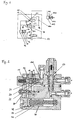
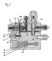
- Fig. 1 shows a schematic representation of the structure of the invention Start-up control. Between the pressure supply P and the piston-cylinder unit 100, the control valve 10 is provided, which is loaded with the spring 14. The feather 14 causes the control valve 10 to not act on the hydraulic medium Condition is in the open position.
- the one shown in FIG. 4 begins Pressure build-up.
- the piston 102 of the piston-cylinder unit is located or the multi-plate clutch in the desired position, there is a Pressure increase in the first connection line 22.
- the pressure increase causes the piston 12 of the control valve 10 is exerted to the left. If this exceeds the spring force of the spring 14, the piston according to FIG. 4 follows moves left, causing the spool of control valve 10 to the closed position is moved.
- This movement of the piston 12 of the control valve 10 causes the bores 110 of the housing 11 no longer in connection with the bores 120 of the piston 12 stand, but are offset from these in such a way that the first connecting line 22 is separated from the second connecting line 20 in a fluid-tight manner.
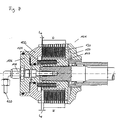
- the disk pack 130 connects the inner driver 140 in the engaged state the outer driver 150 and thus, for example, a gear shaft with a shaft driven by a motor.
- the state of intervention is achieved that the piston 102 against the force of the return springs 104 according to FIG. 7 after is moved to the right and thus compresses the disk pack 130.
Landscapes
- Engineering & Computer Science (AREA)
- General Engineering & Computer Science (AREA)
- Physics & Mathematics (AREA)
- Fluid Mechanics (AREA)
- Mechanical Engineering (AREA)
- Hydraulic Clutches, Magnetic Clutches, Fluid Clutches, And Fluid Joints (AREA)
- Injection Moulding Of Plastics Or The Like (AREA)
- Valve Device For Special Equipments (AREA)
- Fluid-Pressure Circuits (AREA)
Abstract
Description
- Fig. 1
- eine schematische Darstellung der erfindungsgemäßen Anlaufsteuerung,
- Fig. 2
- eine Schnittdarstellung der erfindungsgemäßen Anlaufsteuerung ohne Hydraulikmedium,
- Fig. 3
- die Anlaufsteuerung gemäß Fig. 2 während der Füllung des Kolbenraums der Lamellenkupplung,
- Fig. 4
- die Anlaufsteuerung gemäß Fig. 2 nach Beendigung der Füllung des Kolbenraums und bei Beginn des Druckaufbaus,
- Fig. 5
- die Anlaufsteuerung gemäß Fig. 2 nach Abschluß des Druckaufbaus,
- Fig. 6
- eine perspektivische Darstellung der erfindungsgemäßen Anlaufsteuerung in einer auseinandergezogenen Darstellung und
- Fig. 7
- eine Längsschnittdarstellung durch eine Lamellenkupplung.
Claims (15)
- Anlaufsteuerung zum Ansteuern einer hydraulischen Kolben-Zylinder-Einheit (100), insbesondere zum Ansteuern einer Lamellenkupplung (101), mit1. einem Steuerventil (10), das in eine Offenstellung und eine Schließstellung bewegbar ist,2. einer mit der hydraulischen Kolben-Zylinder-Einheit (100) verbindbaren ersten Anschlußleitung (22) sowie mit einer mit einer Druckspeisung (P) verbindbaren zweiten Anschlußleitung (20),2.1 wobei die erste (22) und die zweite Anschlußleitung (20) mit dem Steuerventil (10) in Verbindung stehen2.2 und wobei die erste Anschlußleitung (22) derart ausgeführt ist, daß bei deren Druckbeaufschlagung auf das Steuerventil (10) eine in Schließstellung wirkende Kraft erzeugbar ist,3. einer ersten Steuerleitung (24), die mit dem Steuerventil (10) derart in Verbindung steht, daß bei deren Druckbeaufschlagung auf das Steuerventil (10) eine in Offenstellung wirkende Kraft erzeugbar ist, sowie mit4. einem Drosselelement (30), dessen Zulauf (32) mit der Druckspeisung (P) verbindbar ist und dessen Ablauf (34) mit einem Druckspeicher (40) sowie mit der ersten Steuerleitung (24) in Verbindung steht,5. wobei das Steuerventil (10) derart ausgeführt ist, daß es von der Offenstellung in die Schließstellung bewegt wird, wenn die in der ersten Anschlußleitung (22) wirkende Druckkraft die in der ersten Steuerleitung (24) wirkende Druckkraft um einen vorgegebenen Betrag übersteigt.
- Anlaufsteuerung nach Anspruch 1, dadurch gekennzeichnet, daß eine zweite Steuerleitung vorgesehen ist, die mit der ersten Anschlußleitung (22) sowie mit dem Steuerventil (10) in Verbindung steht, und die derart ausgeführt ist, daß bei Druckbeaufschlagung der zweiten Steuerleitung auf das Steuerventil (10) eine in Schließstellung wirkende Kraft erzeugbar ist.
- Anlaufsteuerung nach Anspruch 1 oder 2, dadurch gekennzeichnet, daß eine Feder (14) vorgesehen ist, durch die das Steuerventil (10) in Offenstellung vorbelastet ist.
- Anlaufsteuerung nach einem oder mehreren der Ansprüche 1 bis 3, dadurch gekennzeichnet, daß eine elektrische Meß- und Steuereinheit vorgesehen ist, durch die die Drückeerfaßbar und auswertbar sind und durch die in Abhängigkeit der Auswertung eine in Offen- oder Schließstellung des Steuerventils (10) wirkende Kraft ausübbar ist.1. in der ersten Steuerleitung (24) sowie2. in der ersten Anschlußleitung (22) und/oder in der zweiten Steuerleitung
- Anlaufsteuerung nach einem oder mehreren der Ansprüche 1 bis 4, dadurch gekennzeichnet, daß ein Magnetventil (50) vorgesehen ist, durch das die Anlaufsteuerung von der Druckspeisung (P) absperrbar ist.
- Anlaufsteuerung nach einem oder mehreren der Ansprüche 1 bis 5, dadurch gekennzeichnet, daß das Drosselelement (30) und/oder das Steuerventil (10) eine Bypassleitung (36, 16) aufweisen, in der ein Rückschlagventil (160, 360) vorgesehen ist, mittels dessen Hydraulikmedium aus dem Druckspeicher (40) und/oder aus der Kolben-Zylinder-Einheit (100) abführbar ist.
- Anlaufsteuerung nach einem oder mehreren der Ansprüche 1 bis 6, dadurch gekennzeichnet, daß der Druckspeicher (40) eine Kolben-Zylinder-Einheit umfaßt, deren Kolbenraum (42) mit dem Ablauf (34) des Drosselelementes (30) in Verbindung steht und deren Kolben (44) entgegen der im Kolbenraum (42) herrschenden Druckkraft durch eine Feder (46) belastet ist.
- Anlaufsteuerung nach Anspruch 7, dadurch gekennzeichnet, daß die Kolben-Zylinder-Einheit des Druckspeichers (40) eine Ablaufleitung (48) aufweist, mittels derer das den Kolben (42) passierende Hydraulikmedium abführbar ist.
- Anlaufsteuerung nach einem oder mehreren der Ansprüche 1 bis 8, dadurch gekennzeichnet, daß der beim Durchströmen des Drosselelementes (30) erzeugbare Druckabfall verstellbär ist.
- Anlaufsteuerung nach einem oder mehreren der Ansprüche 1 bis 9, dadurch gekennzeichnet, daß das Steuerventil (10) ein Gehäuse (11) und einen darin bewegbar aufgenommenen Kolben (12) aufweist, der in Offenstellung des Steuerventils (10) vorbelastet ist und der mit der ersten Steuerleitung (24) sowie mit der ersten Anschlußleitung (22) in Verbindung steht und durch den das Steuerventil (10) in Abhängigkeit von der Kolbenposition geöffnet oder geschlossen werden kann.
- Anlaufsteuerung nach Anspruch 10, dadurch gekennzeichnet, daß das Gehäuse (11) mit der zweiten Anschlußleitung (20) in Verbindung stehende Bohrungen (110) aufweist, daß der Kolben (12) in dem mit der ersten Anschlußleitung (22) in Verbindung stehenden Endbereich als Hohlzylinder ausgeführt ist, wobei die Wandung des Hohlzylinders Bohrungen (120) aufweist, die in Offenstellung des Steuerventils (10) mit den Bohrungen (110) des Gehäuses (11) in Verbindung stehen und in Schließstellung des Steuerventils (10) von diesen fluiddicht getrennt sind.
- Lamellenkupplung (101) mit einem durch einen Kolben (102) zusammenpreßbaren Lamellenpaket (130), mit einer Zuführung (120) für ein Hydraulikmedium, die derart angeordnet ist, daß auf den Kolben (102) bei Druckbeaufschlagung der Zuführung (120) eine auf das Lamellenpaket (130) gerichtete Kraft erzeugbar ist, sowie mit einem oder mehreren Rückstellelementen, die auf den Kolben eine entgegen der durch das Hydraulikmedium aufbringbaren Kraft wirkende Gegenkraft aufbringen,
dadurch gekennzeichnet,
daß die Lamellenkupplung (101) eine Anlaufsteuerung nach einem oder mehreren der Ansprüche 1 bis 11 aufweist, wobei die Zuführung (120) der Lamellenkupplung (101) mit der ersten Anschlußleitung (22) der Anlaufsteuerung in Verbindung steht. - Lamellenkupplung (101) nach Anspruch 12, dadurch gekennzeichnet, daß die Rückstellelemente als Federn (104) ausgeführt sind.
- Fahrzeug, insbesondere Nutzfahrzeug, mit einer mit einem Hydraulikmedium beaufschlagbaren Kolben-Zylinder-Einheit (100),
dadurch gekennzeichnet,
daß eine Anlaufsteuerung nach einem oder mehreren der Ansprüche 1 bis 11 vorgesehen ist, durch die die Kolben-Zylinder-Einheit (100) ansteuerbar ist. - Fahrzeug nach Anspruch 14, dadurch gekennzeichnet, daß die Kolben-Zylinder-Einheit (100) Bestandteil einer Lamellenkupplung (101) ist.
Applications Claiming Priority (2)
| Application Number | Priority Date | Filing Date | Title |
|---|---|---|---|
| DE19854453 | 1998-11-25 | ||
| DE1998154453 DE19854453A1 (de) | 1998-11-25 | 1998-11-25 | Anlaufsteuerung zum Ansteuern einer hydraulischen Kolben-Zylinder-Einheit |
Publications (3)
| Publication Number | Publication Date |
|---|---|
| EP1004786A2 true EP1004786A2 (de) | 2000-05-31 |
| EP1004786A3 EP1004786A3 (de) | 2003-09-24 |
| EP1004786B1 EP1004786B1 (de) | 2004-12-22 |
Family
ID=7889031
Family Applications (1)
| Application Number | Title | Priority Date | Filing Date |
|---|---|---|---|
| EP19990119645 Expired - Lifetime EP1004786B1 (de) | 1998-11-25 | 1999-10-04 | Anlaufsteuerung zum Ansteuern einer hydraulischen Kolben-Zylinder-Einheit |
Country Status (5)
| Country | Link |
|---|---|
| US (1) | US6244410B1 (de) |
| EP (1) | EP1004786B1 (de) |
| AT (1) | ATE285529T1 (de) |
| CA (1) | CA2290834A1 (de) |
| DE (2) | DE19854453A1 (de) |
Families Citing this family (7)
| Publication number | Priority date | Publication date | Assignee | Title |
|---|---|---|---|---|
| DE10210877A1 (de) * | 2002-03-12 | 2003-11-27 | Wabco Gmbh & Co Ohg | Ventileinrichtung für Stellzylinder |
| DE50303114D1 (de) * | 2003-07-26 | 2006-06-01 | Zf Sachs Ag | Hydraulisch betätigbare Lamellenkupplung |
| US6948524B1 (en) * | 2004-03-16 | 2005-09-27 | General Motors Corporation | Pressure holding apparatus for a torque-transmitting mechanism |
| US9835207B2 (en) * | 2013-02-26 | 2017-12-05 | Borgwarner Torqtransfer Systems Ab | Method for operating a hydraulic disc coupling in an AWD vehicle and a coupling therefore |
| JP7427503B2 (ja) * | 2020-03-31 | 2024-02-05 | 株式会社エクセディ | クラッチレリーズ装置 |
| CN112211930B (zh) * | 2020-10-26 | 2021-03-30 | 湖北福邦汽车配件科技有限公司 | 一种增压式油压控制系统 |
| US20240110602A1 (en) * | 2022-09-29 | 2024-04-04 | Honda Motor Co., Ltd. | Hydraulic circuit for power transmission device |
Family Cites Families (7)
| Publication number | Priority date | Publication date | Assignee | Title |
|---|---|---|---|---|
| US3583422A (en) * | 1967-10-19 | 1971-06-08 | Zahnradfabrik Friedrichshafen | Valve construction for controlled pressure buildup in fluid-operated brake or clutch |
| US3550507A (en) * | 1968-08-16 | 1970-12-29 | Allis Chalmers Mfg Co | Hydraulic valve |
| US3566716A (en) * | 1969-07-22 | 1971-03-02 | Int Harvester Co | Clutch cylinder circuit and charging valve therefor |
| US3991865A (en) * | 1974-02-28 | 1976-11-16 | Kabushiki Kaisha Komatsu Seisakusho | Device for gradually increasing hydraulic pressure |
| US4046162A (en) * | 1976-05-14 | 1977-09-06 | Deere & Company | Modulation control valve for clutches |
| JPH085394Y2 (ja) * | 1988-05-11 | 1996-02-14 | 株式会社小松製作所 | クラッチ油圧制御装置 |
| US5083646A (en) * | 1989-08-07 | 1992-01-28 | Kabushiki Kaisha Toyoda Jidoshokki Seisakusho | Hydraulic device for operating a clutch in an industrial vehicle |
-
1998
- 1998-11-25 DE DE1998154453 patent/DE19854453A1/de not_active Ceased
-
1999
- 1999-10-04 DE DE59911322T patent/DE59911322D1/de not_active Expired - Fee Related
- 1999-10-04 AT AT99119645T patent/ATE285529T1/de not_active IP Right Cessation
- 1999-10-04 EP EP19990119645 patent/EP1004786B1/de not_active Expired - Lifetime
- 1999-11-24 US US09/448,955 patent/US6244410B1/en not_active Expired - Fee Related
- 1999-11-25 CA CA002290834A patent/CA2290834A1/en not_active Abandoned
Non-Patent Citations (1)
| Title |
|---|
| None |
Also Published As
| Publication number | Publication date |
|---|---|
| EP1004786B1 (de) | 2004-12-22 |
| EP1004786A3 (de) | 2003-09-24 |
| DE19854453A1 (de) | 2000-06-08 |
| ATE285529T1 (de) | 2005-01-15 |
| DE59911322D1 (de) | 2005-01-27 |
| US6244410B1 (en) | 2001-06-12 |
| CA2290834A1 (en) | 2000-05-25 |
Similar Documents
| Publication | Publication Date | Title |
|---|---|---|
| EP2382520B1 (de) | Proportional-druckregelventil und seine verwendung für hydraulisch betätigbare kupplungen | |
| EP2960561B1 (de) | Hydraulikventil | |
| EP1519082B1 (de) | Ansteuereinrichtung für hydraulisch betätigbare Kupplungen sowie Verfahren zur Ansteuerung von hydraulisch betätigbarer Kupplungen | |
| EP3058250A2 (de) | Hydraulische steuerungsvorrichtung für ein automatikgetriebe | |
| DE1576088B2 (de) | Schnellentlastungsventil fuer hydraulische kraftzylinder | |
| EP0103250B1 (de) | Steuerventil zur Flüssigkeitssteuerung | |
| DE10019254C2 (de) | Drucksteuerventil | |
| DE2834145C2 (de) | Hydraulische Steuervorrichtung für den Kolben einer Kolben-Zylinderbetätigungseinrichtung einer Reibungskupplung | |
| EP1004786B1 (de) | Anlaufsteuerung zum Ansteuern einer hydraulischen Kolben-Zylinder-Einheit | |
| EP1437519B1 (de) | Geberzylinder für Kupplungsausrücksysteme | |
| DE3040321C2 (de) | Inchventil für einen hydrostatischen Fahrantrieb | |
| DE3725492A1 (de) | Kraftrad mit einer mehrscheibenkupplung | |
| EP1629208A1 (de) | Proportional-druckregelventil | |
| EP0059968A1 (de) | Steuerung für eine Flüssigkeitskupplung | |
| DE2212679B2 (de) | Hydraulische Schaltvorrichtung für Lastschaltgetriebe mit Sicherung gegen Fehlschaltungen | |
| DD150099A5 (de) | Apparat zum einstellen des toten spiels | |
| DE19757157C2 (de) | Hydraulischer Linearantrieb | |
| DE2401101C3 (de) | Steuerschieber-Vorrichtung zur allmählichen Steigerung des Flüssigkeitsdrucks in einer hydraulischen Steuerleitung für ein Gangschalt-Getriebe | |
| EP1446276B1 (de) | Antriebsvorrichtung, insbesondere für die schliesseinheit, die einspritzeinheit oder die auswerfer einer kunststoffspritzgiessmaschine | |
| DE102008007047B4 (de) | Anfahreinheit | |
| WO2019086424A1 (de) | Ventil, hydrauliksystem und kraftfahrzeuggetriebe | |
| DE4420164A1 (de) | Kombiniertes Druck- und Schaltventil | |
| EP0139776A1 (de) | Ventil | |
| DE2162885C3 (de) | Kickdown-Einheit für ein automatisches Kraftfahrzeuggetriebe | |
| DE102015204816A1 (de) | Getriebevorrichtung mit wenigstens einem fluidisch betätigbaren Schaltelement |
Legal Events
| Date | Code | Title | Description |
|---|---|---|---|
| PUAI | Public reference made under article 153(3) epc to a published international application that has entered the european phase |
Free format text: ORIGINAL CODE: 0009012 |
|
| AK | Designated contracting states |
Kind code of ref document: A2 Designated state(s): AT BE CH CY DE DK ES FI FR GB GR IE IT LI LU MC NL PT SE |
|
| AX | Request for extension of the european patent |
Free format text: AL;LT;LV;MK;RO;SI |
|
| PUAL | Search report despatched |
Free format text: ORIGINAL CODE: 0009013 |
|
| AK | Designated contracting states |
Kind code of ref document: A3 Designated state(s): AT BE CH CY DE DK ES FI FR GB GR IE IT LI LU MC NL PT SE |
|
| AX | Request for extension of the european patent |
Extension state: AL LT LV MK RO SI |
|
| 17P | Request for examination filed |
Effective date: 20031205 |
|
| GRAP | Despatch of communication of intention to grant a patent |
Free format text: ORIGINAL CODE: EPIDOSNIGR1 |
|
| AKX | Designation fees paid |
Designated state(s): AT BE CH CY DE DK ES FI FR GB GR IE IT LI LU MC NL PT SE |
|
| GRAS | Grant fee paid |
Free format text: ORIGINAL CODE: EPIDOSNIGR3 |
|
| GRAA | (expected) grant |
Free format text: ORIGINAL CODE: 0009210 |
|
| AK | Designated contracting states |
Kind code of ref document: B1 Designated state(s): AT BE CH CY DE DK ES FI FR GB GR IE IT LI LU MC NL PT SE |
|
| PG25 | Lapsed in a contracting state [announced via postgrant information from national office to epo] |
Ref country code: NL Free format text: LAPSE BECAUSE OF FAILURE TO SUBMIT A TRANSLATION OF THE DESCRIPTION OR TO PAY THE FEE WITHIN THE PRESCRIBED TIME-LIMIT Effective date: 20041222 Ref country code: IT Free format text: LAPSE BECAUSE OF FAILURE TO SUBMIT A TRANSLATION OF THE DESCRIPTION OR TO PAY THE FEE WITHIN THE PRE;WARNING: LAPSES OF ITALIAN PATENTS WITH EFFECTIVE DATE BEFORE 2007 MAY HAVE OCCURRED AT ANY TIME BEFORE 2007. THE CORRECT EFFECTIVE DATE MAY BE DIFFERENT FROM THE ONE RECORDED.SCRIBED TIME-LIMIT Effective date: 20041222 Ref country code: IE Free format text: LAPSE BECAUSE OF FAILURE TO SUBMIT A TRANSLATION OF THE DESCRIPTION OR TO PAY THE FEE WITHIN THE PRESCRIBED TIME-LIMIT Effective date: 20041222 Ref country code: GB Free format text: LAPSE BECAUSE OF FAILURE TO SUBMIT A TRANSLATION OF THE DESCRIPTION OR TO PAY THE FEE WITHIN THE PRESCRIBED TIME-LIMIT Effective date: 20041222 Ref country code: FI Free format text: LAPSE BECAUSE OF FAILURE TO SUBMIT A TRANSLATION OF THE DESCRIPTION OR TO PAY THE FEE WITHIN THE PRESCRIBED TIME-LIMIT Effective date: 20041222 |
|
| REG | Reference to a national code |
Ref country code: GB Ref legal event code: FG4D Free format text: NOT ENGLISH |
|
| REG | Reference to a national code |
Ref country code: CH Ref legal event code: EP |
|
| REG | Reference to a national code |
Ref country code: IE Ref legal event code: FG4D Free format text: GERMAN |
|
| REF | Corresponds to: |
Ref document number: 59911322 Country of ref document: DE Date of ref document: 20050127 Kind code of ref document: P |
|
| PG25 | Lapsed in a contracting state [announced via postgrant information from national office to epo] |
Ref country code: SE Free format text: LAPSE BECAUSE OF FAILURE TO SUBMIT A TRANSLATION OF THE DESCRIPTION OR TO PAY THE FEE WITHIN THE PRESCRIBED TIME-LIMIT Effective date: 20050322 Ref country code: GR Free format text: LAPSE BECAUSE OF FAILURE TO SUBMIT A TRANSLATION OF THE DESCRIPTION OR TO PAY THE FEE WITHIN THE PRESCRIBED TIME-LIMIT Effective date: 20050322 Ref country code: DK Free format text: LAPSE BECAUSE OF FAILURE TO SUBMIT A TRANSLATION OF THE DESCRIPTION OR TO PAY THE FEE WITHIN THE PRESCRIBED TIME-LIMIT Effective date: 20050322 |
|
| PG25 | Lapsed in a contracting state [announced via postgrant information from national office to epo] |
Ref country code: ES Free format text: LAPSE BECAUSE OF FAILURE TO SUBMIT A TRANSLATION OF THE DESCRIPTION OR TO PAY THE FEE WITHIN THE PRESCRIBED TIME-LIMIT Effective date: 20050402 |
|
| NLV1 | Nl: lapsed or annulled due to failure to fulfill the requirements of art. 29p and 29m of the patents act | ||
| GBV | Gb: ep patent (uk) treated as always having been void in accordance with gb section 77(7)/1977 [no translation filed] |
Effective date: 20041222 |
|
| REG | Reference to a national code |
Ref country code: IE Ref legal event code: FD4D |
|
| PG25 | Lapsed in a contracting state [announced via postgrant information from national office to epo] |
Ref country code: CY Free format text: LAPSE BECAUSE OF FAILURE TO SUBMIT A TRANSLATION OF THE DESCRIPTION OR TO PAY THE FEE WITHIN THE PRESCRIBED TIME-LIMIT Effective date: 20051004 Ref country code: AT Free format text: LAPSE BECAUSE OF NON-PAYMENT OF DUE FEES Effective date: 20051004 |
|
| PLBE | No opposition filed within time limit |
Free format text: ORIGINAL CODE: 0009261 |
|
| STAA | Information on the status of an ep patent application or granted ep patent |
Free format text: STATUS: NO OPPOSITION FILED WITHIN TIME LIMIT |
|
| PG25 | Lapsed in a contracting state [announced via postgrant information from national office to epo] |
Ref country code: MC Free format text: LAPSE BECAUSE OF NON-PAYMENT OF DUE FEES Effective date: 20051031 Ref country code: LU Free format text: LAPSE BECAUSE OF NON-PAYMENT OF DUE FEES Effective date: 20051031 Ref country code: LI Free format text: LAPSE BECAUSE OF NON-PAYMENT OF DUE FEES Effective date: 20051031 Ref country code: CH Free format text: LAPSE BECAUSE OF NON-PAYMENT OF DUE FEES Effective date: 20051031 Ref country code: BE Free format text: LAPSE BECAUSE OF NON-PAYMENT OF DUE FEES Effective date: 20051031 |
|
| ET | Fr: translation filed | ||
| 26N | No opposition filed |
Effective date: 20050923 |
|
| PG25 | Lapsed in a contracting state [announced via postgrant information from national office to epo] |
Ref country code: DE Free format text: LAPSE BECAUSE OF NON-PAYMENT OF DUE FEES Effective date: 20060503 |
|
| REG | Reference to a national code |
Ref country code: CH Ref legal event code: PL |
|
| PG25 | Lapsed in a contracting state [announced via postgrant information from national office to epo] |
Ref country code: FR Free format text: LAPSE BECAUSE OF NON-PAYMENT OF DUE FEES Effective date: 20060630 |
|
| REG | Reference to a national code |
Ref country code: FR Ref legal event code: ST Effective date: 20060630 |
|
| BERE | Be: lapsed |
Owner name: *LIEBHERR MARKUS Effective date: 20051031 |
|
| PG25 | Lapsed in a contracting state [announced via postgrant information from national office to epo] |
Ref country code: PT Free format text: LAPSE BECAUSE OF NON-PAYMENT OF DUE FEES Effective date: 20050522 |