EP1004818B1 - Fahrzeugleuchte - Google Patents
Fahrzeugleuchte Download PDFInfo
- Publication number
- EP1004818B1 EP1004818B1 EP99122983A EP99122983A EP1004818B1 EP 1004818 B1 EP1004818 B1 EP 1004818B1 EP 99122983 A EP99122983 A EP 99122983A EP 99122983 A EP99122983 A EP 99122983A EP 1004818 B1 EP1004818 B1 EP 1004818B1
- Authority
- EP
- European Patent Office
- Prior art keywords
- light
- lens arrangement
- lens
- light source
- scattering
- Prior art date
- Legal status (The legal status is an assumption and is not a legal conclusion. Google has not performed a legal analysis and makes no representation as to the accuracy of the status listed.)
- Expired - Lifetime
Links
- 238000000149 argon plasma sintering Methods 0.000 claims abstract description 30
- 230000003287 optical effect Effects 0.000 claims abstract description 7
- 230000000694 effects Effects 0.000 claims description 3
- 229920003023 plastic Polymers 0.000 claims description 3
- 239000004033 plastic Substances 0.000 claims description 2
- 239000000463 material Substances 0.000 claims 2
- 238000001914 filtration Methods 0.000 claims 1
- 230000006870 function Effects 0.000 description 8
- 230000000712 assembly Effects 0.000 description 1
- 238000000429 assembly Methods 0.000 description 1
- 230000002950 deficient Effects 0.000 description 1
- 238000010304 firing Methods 0.000 description 1
- 230000009131 signaling function Effects 0.000 description 1
Images

Classifications
-
- B—PERFORMING OPERATIONS; TRANSPORTING
- B60—VEHICLES IN GENERAL
- B60Q—ARRANGEMENT OF SIGNALLING OR LIGHTING DEVICES, THE MOUNTING OR SUPPORTING THEREOF OR CIRCUITS THEREFOR, FOR VEHICLES IN GENERAL
- B60Q1/00—Arrangement of optical signalling or lighting devices, the mounting or supporting thereof or circuits therefor
- B60Q1/26—Arrangement of optical signalling or lighting devices, the mounting or supporting thereof or circuits therefor the devices being primarily intended to indicate the vehicle, or parts thereof, or to give signals, to other traffic
-
- F—MECHANICAL ENGINEERING; LIGHTING; HEATING; WEAPONS; BLASTING
- F21—LIGHTING
- F21S—NON-PORTABLE LIGHTING DEVICES; SYSTEMS THEREOF; VEHICLE LIGHTING DEVICES SPECIALLY ADAPTED FOR VEHICLE EXTERIORS
- F21S43/00—Signalling devices specially adapted for vehicle exteriors, e.g. brake lamps, direction indicator lights or reversing lights
- F21S43/20—Signalling devices specially adapted for vehicle exteriors, e.g. brake lamps, direction indicator lights or reversing lights characterised by refractors, transparent cover plates, light guides or filters
- F21S43/255—Filters
-
- F—MECHANICAL ENGINEERING; LIGHTING; HEATING; WEAPONS; BLASTING
- F21—LIGHTING
- F21S—NON-PORTABLE LIGHTING DEVICES; SYSTEMS THEREOF; VEHICLE LIGHTING DEVICES SPECIALLY ADAPTED FOR VEHICLE EXTERIORS
- F21S43/00—Signalling devices specially adapted for vehicle exteriors, e.g. brake lamps, direction indicator lights or reversing lights
- F21S43/20—Signalling devices specially adapted for vehicle exteriors, e.g. brake lamps, direction indicator lights or reversing lights characterised by refractors, transparent cover plates, light guides or filters
- F21S43/26—Refractors, transparent cover plates, light guides or filters not provided in groups F21S43/235 - F21S43/255
Definitions
- the invention relates to a vehicle lamp with at least one light function, with a housing with a light source in the housing and with one the housing final lens, being between light source and lens a light collecting lens arrangement is arranged between the light source and the light-collecting lens arrangement arranged a light-scattering lens arrangement is, the light collecting lens assembly is a Fresnel lens that is opposite to the optically-free cover plate (A) is arranged in a spatially recessed manner in the housing and the light-scattering lens arrangement surrounds the light source in a cap shape
- a vehicle lamp is known from German Offenlegungsschrift DE 196 47 357 A1 which has a housing which is covered by an end plate.
- a light source is arranged in the housing.
- a light-collecting lens arrangement is arranged, which is designed as a Fresnel lens.
- the Fresnel lens is included arranged spatially set back in the housing relative to the end plate.
- the End plate has light-scattering and / or in the known prior art light-gathering lens elements to combine with the Fresnel lens Predefined light distribution of the vehicle lamp and the one assigned to it Achieve light function.
- a disadvantage of this known vehicle lamp is that that the lens elements in the lens have a brilliant appearance the lamp is not given, since the lens elements in the free view from the outside prevent the lamp.
- a vehicle lamp with at least one light function with a housing, with a light source in the housing and with a cover plate that closes the housing is known, wherein a light-collecting lens arrangement is arranged between the light source and the lens, the light-collecting lens arrangement is a Fresnel lens, which is arranged spatially set back in the housing with respect to the firing disc, and the light-scattering lens arrangement surrounds the light source in a cap shape.
- the lens of the known vehicle lamp is referred to in JP 03 25 40 04 as "lens", from which it can be deduced that it exerts an optical effect and is therefore provided with optical elements. Such elements prevent a clear view of the lamp.
- the invention has for its object to provide a vehicle lamp, which has a brilliant appearance with a simple technical structure.
- the lens of the at least one light function is optics-free is trained because it allows a clear view of the lamp and a brilliant appearance is achieved.
- the light source is particularly advantageous to design the light source as a colored light source and / or the light-collecting lens arrangement and / or the light-scattering
- design lens arrangement as a color filter, because the advantage is achieved that the Luminaire can have any color design when switched off is independent of the signal function of the vehicle lamp.
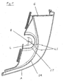
- Figure 1 shows a horizontal section through a vehicle lamp, the one Has housing (G), which is covered by a cover plate (A).
- the Vehicle lights can have a single light function or one so-called multi-chamber luminaire, in which several light functions are integrated.
- a is not shown Socket arrangement of a light source (L) indicated only schematically in the housing (G) arranged.
- the light source (L) has a focal point (B) and can be white or emit colored light.
- the lens (A) is optically free and made of a clear or clear colored plastic.
- a light-collecting lens arrangement (SA) which is designed as a Fresnel lens, arranged.
- SA light-collecting lens arrangement
- this light-scattering lens arrangement (ST) cap-shaped and surrounds the light source, so that all essential In the housing (G) is spatially opposite the lens (A) sets back a light collecting lens assembly (SA) that acts as a Fresnel lens is arranged.
- SA light collecting lens assembly
- In the beam path between the Light source and the light-collecting lens arrangement (SA) is one light-scattering lens arrangement (ST) arranged.
- this light-scattering lens arrangement (ST) is cap-shaped trained and surrounds the light source, so that all essential light components get a pre-alignment by the light-scattering lens arrangement (ST), before they hit the light-collecting lens arrangement (SA).
- the light-collecting lens arrangement (SA) and the light-scattering lens arrangement (ST) are coordinated so that the vehicle lamp for the light function generates the required light distribution.
- the light-collecting lens arrangement (SA) extends in Form of a Fresnel lens set back in the housing (G) essentially above the entire area of the vehicle lamp.
- the light-collecting lens arrangement (SA) and / or the light-scattering Lens arrangement (ST) can be designed as a color filter.
- a clear lens (A) or a colored one transparent lens (A) and / or a clear or colored The light source thus results in any color design options Luminaire not switched on, the signal color of the light function can be complied with in accordance with the legal requirements.
- the generation of the light distribution by the light-scattering lens arrangement (ST) and the light collecting lens assembly (SA) is set back in the housing is generated and the lens (A) gives an insight into the lamp enables a brilliant appearance that reflects the depth of the lamp taught.
- FIG 2 is the light-scattering lens arrangement (ST), which is exemplary here is cap-shaped, shown in front view.
- This lens arrangement has, for example, a central optics area (ZO) with concentric arranged, light-scattering lens elements (LE).
- ZO central optics area
- LE light-scattering lens elements
- At the central Optics area (ZO) closes an area with also light-scattering Lens elements (LE), which are essentially in the direction of the Extend the center (M) of the central optics area (ZO).
- the light-scattering lens elements ((LE) can be used both with and with radii provided lens elements (LE) or as prisms.
- FIG 3 is a horizontal section through the light-scattering according to Figure 2 Lens arrangement (ST) shown. Examples are from the focus (B) of the light source (L), not shown, two light beams (LS) are drawn in illustrate the light-scattering effect of the lens elements (LE).
- Figure 1 is a comparable beam path for two light rays (LS) is drawn in also the light-collecting effect of the light-collecting lens arrangement (SA) clarified.
Landscapes
- Engineering & Computer Science (AREA)
- General Engineering & Computer Science (AREA)
- Mechanical Engineering (AREA)
- Non-Portable Lighting Devices Or Systems Thereof (AREA)
- Glass Compositions (AREA)
- Inorganic Insulating Materials (AREA)
Description
wobei zwischen Lichtquelle und Abschlußscheibe eine lichtsammelnde Linsenanordnung angeordnet ist, die lichtsammelnde Linsenanordnung eine Fresnetlinse ist, die gegenüber der Abschtußscheibe räumlich zurückversetzt im Gehäuse angeordnet ist und die lichtstreuende Linsenanordnung, die Lichtquelle kappenförmig umgibt. Die Abschlußscheibeder bekannten Fahrzeugleuchte wird in JP 03 25 40 04 als "lens" bezeichnet, woraus abzuleiten ist, daß diese eine optische Wirkung aus übt und dem = zufolge mit optische Elemente versehen ist. Solche Elemente verhindern den freien Blick in die Leuchte hinein. Somit weist die bekannte Fahrzeugleuchte ein mangel = holes brillantes Erscheinungsbild auf.
- A
- Abschlußscheibe
- B
- Brennpunkt
- G
- Gehäuse
- L
- Lichtquelle
- LE
- Linsenelemente
- LS
- Lichtstrahlen
- M
- Mittelpunkt
- SA
- lichtsammelnde Linsenanordnung
- ST
- lichtstreuende Linsenanordnung
- ZO
- zentraler Optikbereich
Claims (6)
- Fahrzeugleuchte mit mindestens einer Lichtfunktion, mit einem Gehäuse (G), mit einer Lichtquelle (L) in dem Gehäuse (G) und mit einer das Gehäuse (G) abschließenden Abschlußscheibe (A), wobei zwischen Lichtquelle (L) und Abschlußscheibe (A) eine lichtsammelnde Linsenanordnung (SA) angeordnet ist, und zwischen der Lichtquelle (L) und der lichtsammelnden Linsenanordnung (SA) eine lichtstreuende Linsenanordnung (ST) angeordnet ist, die lichtsammelnde Linsenanordnung (SA) eine Fresnellinse ist, die gegenüber der Abschlußscheibe (A) räumlich zurückversetzt im Gehäuse (G) angeordnet ist und die lichtstreuende Linsenanordnung (ST) die Lichtquelle (L) kappenförmig umgibt, dadurch gekennzeichnet, dass die lichtstreuende Linsenanordnung (ST) einen in Hauptlichtabstrahlrichtung angeordneten zentralen Optikbereich (ZO) mit konzentrisch angeordneten, lichtstreuenden Linsenelementen (LE) aufweist, die lichtstreuende Linsenanordnung (ST) in dem sich an den zentralen Optikbereich (ZO) anschließenden Bereich lichtstreuende Linsenelemente (LE) aufweist, die sich im wesentlichen in Richtung auf den Mittelpunkt (M) des zentralen Optikbereiches (ZO) hin erstrecken und daß die Abschlußscheibe (A) der mindestens einen Lichtfunktion optikfrei ausgebildet ist.
- Fahrzeugleuchte nach Anspruch 1, dadurch gekennzeichnet, daß die optikfreie Abschlußscheibe (A) aus glasklarem Kunststoff gefertigt ist.
- Fahrzeugleuchte nach einem der vorstehenden Ansprüche, dadurch gekennzeichnet, daß die optikfreie klare Abschlußscheibe (A) aus einem farbigen Kunststoff gefertigt ist.
- Fahrzeugleuchte nach einem der vorstehenden Ansprüche, dadurch gekennzeichnet, daß die lichtsammelnde Linsenanordnung (SA) und/oder die lichtstreuende Linsenanordnung (ST) als Farbfilter ausgebildet sind.
- Fahrzeugleuchte nach einem der vorstehenden Ansprüche, dadurch gekennzeichnet, daß die Lichtquelle (L) farbiges Licht abstrahlt.
- Fahrzeugleuchte nach einem der vorstehenden Ansprüche, dadurch gekennzeichnet, daß die Farbfilter und/oder die Lichtquelle (L) in ihrer Filterwirkung zur Erzeugung einer Signalfarbe aufeinander abgestimmt sind.
Applications Claiming Priority (2)
| Application Number | Priority Date | Filing Date | Title |
|---|---|---|---|
| DE19854303 | 1998-11-25 | ||
| DE19854303A DE19854303A1 (de) | 1998-11-25 | 1998-11-25 | Fahrzeugleuchte |
Publications (3)
| Publication Number | Publication Date |
|---|---|
| EP1004818A2 EP1004818A2 (de) | 2000-05-31 |
| EP1004818A3 EP1004818A3 (de) | 2001-09-26 |
| EP1004818B1 true EP1004818B1 (de) | 2003-10-08 |
Family
ID=7888917
Family Applications (1)
| Application Number | Title | Priority Date | Filing Date |
|---|---|---|---|
| EP99122983A Expired - Lifetime EP1004818B1 (de) | 1998-11-25 | 1999-11-19 | Fahrzeugleuchte |
Country Status (4)
| Country | Link |
|---|---|
| EP (1) | EP1004818B1 (de) |
| AT (1) | ATE251734T1 (de) |
| DE (2) | DE19854303A1 (de) |
| ES (1) | ES2207903T3 (de) |
Families Citing this family (1)
| Publication number | Priority date | Publication date | Assignee | Title |
|---|---|---|---|---|
| DE10339878A1 (de) * | 2003-08-29 | 2005-06-16 | Hella Kgaa Hueck & Co. | Fahrzeugaußenleuchte |
Family Cites Families (7)
| Publication number | Priority date | Publication date | Assignee | Title |
|---|---|---|---|---|
| DE2908453C2 (de) * | 1979-03-05 | 1981-12-03 | Westfälische Metall Industrie KG Hueck & Co, 4780 Lippstadt | Farbiges Licht abgebende Signalleuchte, insbesondere für Fahrzeuge |
| FR2522391A1 (fr) * | 1982-03-01 | 1983-09-02 | Marchal Equip Auto | Perfectionnements aux dispositifs emetteurs de lumiere pour vehicules automobiles |
| FR2648542B1 (fr) * | 1989-06-19 | 1993-05-14 | Axo Cie Equip Automobiles | Perfectionnements aux feux de signalisation de vehicules automobiles |
| JP2860135B2 (ja) * | 1990-03-05 | 1999-02-24 | スタンレー電気株式会社 | 車両用信号灯のインナーレンズ |
| JP3218551B2 (ja) * | 1993-08-27 | 2001-10-15 | スタンレー電気株式会社 | 車両用信号灯具 |
| JPH07161205A (ja) * | 1993-12-06 | 1995-06-23 | Stanley Electric Co Ltd | 車両用信号灯具 |
| DE19647357A1 (de) * | 1996-11-15 | 1998-05-20 | Hella Kg Hueck & Co | Fahrzeugleuchte |
-
1998
- 1998-11-25 DE DE19854303A patent/DE19854303A1/de not_active Withdrawn
-
1999
- 1999-11-19 DE DE59907276T patent/DE59907276D1/de not_active Expired - Lifetime
- 1999-11-19 EP EP99122983A patent/EP1004818B1/de not_active Expired - Lifetime
- 1999-11-19 AT AT99122983T patent/ATE251734T1/de not_active IP Right Cessation
- 1999-11-19 ES ES99122983T patent/ES2207903T3/es not_active Expired - Lifetime
Also Published As
| Publication number | Publication date |
|---|---|
| ATE251734T1 (de) | 2003-10-15 |
| ES2207903T3 (es) | 2004-06-01 |
| EP1004818A3 (de) | 2001-09-26 |
| EP1004818A2 (de) | 2000-05-31 |
| DE59907276D1 (de) | 2003-11-13 |
| DE19854303A1 (de) | 2000-06-29 |
Similar Documents
| Publication | Publication Date | Title |
|---|---|---|
| DE19652159B4 (de) | Beleuchtungseinrichtung für Fahrzeuge | |
| DE10249113B4 (de) | Fahrzeugleuchte, insbesondere Heckleuchte, vorzugsweise für Kraftfahrzeuge | |
| DE102012202508B4 (de) | Lichtleitervorrichtung für eine Kraftfahrzeugleuchte | |
| DE102013207850A1 (de) | Lichtmodul für einen Kraftfahrzeugscheinwerfer | |
| DE102015101301A1 (de) | Beleuchtungsvorrichtung und Fahrzeug mit derselben | |
| EP2179215A1 (de) | Fahrzeugleuchtvorrichtung mit einem zusatzreflektor zum seitlichen umlenken eines lichtteils einer lichtquelle | |
| DE10200359B4 (de) | Leuchtenanordnung, insbesondere für Kraftfahrzeuge | |
| WO2020078760A1 (de) | Beleuchtungsvorrichtung für fahrzeuge | |
| EP0718974B1 (de) | Näherungsschalter | |
| DE19646042B4 (de) | Fahrzeug-Beleuchtungseinrichtung | |
| DE10143415A1 (de) | Leuchtenanordnung | |
| EP1190903B1 (de) | Leseleuchte für einen Fahrzeuginnenraum | |
| DE2939329A1 (de) | Signalleuchte, insbesondere blinkleuchte fuer kraftfahrzeuge | |
| DE69712440T2 (de) | Verkehrsampel mit Beleuchtungsvorrichtungen im Boden | |
| EP1004818B1 (de) | Fahrzeugleuchte | |
| DE19940410A1 (de) | Blinkleuchte für Fahrzeuge | |
| DE4312889B4 (de) | Vorwiegend direkt strahlende Leuchte mit einem abgehängten Lichtleitkörper | |
| EP0637716B1 (de) | Lichtscheibe einer mehrere Lichtfunktionen aufweisenden Fahrzeugleuchte | |
| DE3427398A1 (de) | Signalleuchte, insbesondere fuer kraftfahrzeuge | |
| DE19753762A1 (de) | Signalleuchte, insbesondere Kombinationsheckleuchte eines Fahrzeuges | |
| EP0669493B1 (de) | Blinkleuchte | |
| DE102013016346A1 (de) | Fahrzeuginnenraum-Bauteil zur Erzeugung einer Ambientebeleuchtung | |
| DE102021100977A1 (de) | Kraftfahrzeugscheinwerfer mit Lamellen | |
| DE29709279U1 (de) | Kraftfahrzeugleuchte, insbesondere Blinkleuchte | |
| DE3005883A1 (de) | Fahrzeug-signalleuchte |
Legal Events
| Date | Code | Title | Description |
|---|---|---|---|
| PUAI | Public reference made under article 153(3) epc to a published international application that has entered the european phase |
Free format text: ORIGINAL CODE: 0009012 |
|
| AK | Designated contracting states |
Kind code of ref document: A2 Designated state(s): AT BE CH CY DE DK ES FI FR GB GR IE IT LI LU MC NL PT SE Kind code of ref document: A2 Designated state(s): AT DE ES FR GB IT |
|
| AX | Request for extension of the european patent |
Free format text: AL;LT;LV;MK;RO;SI |
|
| PUAL | Search report despatched |
Free format text: ORIGINAL CODE: 0009013 |
|
| AK | Designated contracting states |
Kind code of ref document: A3 Designated state(s): AT BE CH CY DE DK ES FI FR GB GR IE IT LI LU MC NL PT SE |
|
| AX | Request for extension of the european patent |
Free format text: AL;LT;LV;MK;RO;SI |
|
| 17P | Request for examination filed |
Effective date: 20020129 |
|
| AKX | Designation fees paid |
Free format text: AT DE ES FR GB IT |
|
| 17Q | First examination report despatched |
Effective date: 20020521 |
|
| GRAH | Despatch of communication of intention to grant a patent |
Free format text: ORIGINAL CODE: EPIDOS IGRA |
|
| GRAS | Grant fee paid |
Free format text: ORIGINAL CODE: EPIDOSNIGR3 |
|
| GRAA | (expected) grant |
Free format text: ORIGINAL CODE: 0009210 |
|
| AK | Designated contracting states |
Kind code of ref document: B1 Designated state(s): AT DE ES FR GB IT |
|
| PG25 | Lapsed in a contracting state [announced via postgrant information from national office to epo] |
Ref country code: GB Free format text: LAPSE BECAUSE OF FAILURE TO SUBMIT A TRANSLATION OF THE DESCRIPTION OR TO PAY THE FEE WITHIN THE PRESCRIBED TIME-LIMIT Effective date: 20031008 |
|
| REG | Reference to a national code |
Ref country code: GB Ref legal event code: FG4D Free format text: NOT ENGLISH |
|
| REF | Corresponds to: |
Ref document number: 59907276 Country of ref document: DE Date of ref document: 20031113 Kind code of ref document: P |
|
| GBV | Gb: ep patent (uk) treated as always having been void in accordance with gb section 77(7)/1977 [no translation filed] |
Effective date: 20031008 |
|
| REG | Reference to a national code |
Ref country code: ES Ref legal event code: FG2A Ref document number: 2207903 Country of ref document: ES Kind code of ref document: T3 |
|
| ET | Fr: translation filed | ||
| PLBE | No opposition filed within time limit |
Free format text: ORIGINAL CODE: 0009261 |
|
| STAA | Information on the status of an ep patent application or granted ep patent |
Free format text: STATUS: NO OPPOSITION FILED WITHIN TIME LIMIT |
|
| 26N | No opposition filed |
Effective date: 20040709 |
|
| PGFP | Annual fee paid to national office [announced via postgrant information from national office to epo] |
Ref country code: AT Payment date: 20061113 Year of fee payment: 8 |
|
| PGFP | Annual fee paid to national office [announced via postgrant information from national office to epo] |
Ref country code: IT Payment date: 20061130 Year of fee payment: 8 |
|
| PG25 | Lapsed in a contracting state [announced via postgrant information from national office to epo] |
Ref country code: AT Free format text: LAPSE BECAUSE OF NON-PAYMENT OF DUE FEES Effective date: 20071119 |
|
| PG25 | Lapsed in a contracting state [announced via postgrant information from national office to epo] |
Ref country code: IT Free format text: LAPSE BECAUSE OF NON-PAYMENT OF DUE FEES Effective date: 20071119 |
|
| PGFP | Annual fee paid to national office [announced via postgrant information from national office to epo] |
Ref country code: FR Payment date: 20101123 Year of fee payment: 12 |
|
| PGFP | Annual fee paid to national office [announced via postgrant information from national office to epo] |
Ref country code: DE Payment date: 20101117 Year of fee payment: 12 |
|
| PGFP | Annual fee paid to national office [announced via postgrant information from national office to epo] |
Ref country code: ES Payment date: 20101217 Year of fee payment: 12 |
|
| REG | Reference to a national code |
Ref country code: FR Ref legal event code: ST Effective date: 20120731 |
|
| REG | Reference to a national code |
Ref country code: DE Ref legal event code: R119 Ref document number: 59907276 Country of ref document: DE Effective date: 20120601 |
|
| PG25 | Lapsed in a contracting state [announced via postgrant information from national office to epo] |
Ref country code: FR Free format text: LAPSE BECAUSE OF NON-PAYMENT OF DUE FEES Effective date: 20111130 |
|
| REG | Reference to a national code |
Ref country code: ES Ref legal event code: FD2A Effective date: 20130605 |
|
| PG25 | Lapsed in a contracting state [announced via postgrant information from national office to epo] |
Ref country code: DE Free format text: LAPSE BECAUSE OF NON-PAYMENT OF DUE FEES Effective date: 20120601 |
|
| PG25 | Lapsed in a contracting state [announced via postgrant information from national office to epo] |
Ref country code: ES Free format text: LAPSE BECAUSE OF NON-PAYMENT OF DUE FEES Effective date: 20111120 |