EP1004863B1 - Procédé et arrangement de mesure pour déterminer les changements opératoires dans des cuves transportant du verre - Google Patents
Procédé et arrangement de mesure pour déterminer les changements opératoires dans des cuves transportant du verre Download PDFInfo
- Publication number
- EP1004863B1 EP1004863B1 EP99121523A EP99121523A EP1004863B1 EP 1004863 B1 EP1004863 B1 EP 1004863B1 EP 99121523 A EP99121523 A EP 99121523A EP 99121523 A EP99121523 A EP 99121523A EP 1004863 B1 EP1004863 B1 EP 1004863B1
- Authority
- EP
- European Patent Office
- Prior art keywords
- temperature measuring
- temperature
- values
- matrix
- measuring probes
- Prior art date
- Legal status (The legal status is an assumption and is not a legal conclusion. Google has not performed a legal analysis and makes no representation as to the accuracy of the status listed.)
- Revoked
Links
- 239000011521 glass Substances 0.000 title claims abstract description 29
- 238000000034 method Methods 0.000 title claims abstract description 22
- 239000000523 sample Substances 0.000 claims abstract description 33
- 238000002844 melting Methods 0.000 claims abstract description 17
- 230000008018 melting Effects 0.000 claims abstract description 17
- 239000000463 material Substances 0.000 claims abstract description 11
- 238000009413 insulation Methods 0.000 claims abstract description 7
- 230000010259 detection of temperature stimulus Effects 0.000 claims abstract description 4
- 230000003287 optical effect Effects 0.000 claims abstract 4
- 239000011159 matrix material Substances 0.000 claims description 29
- 239000011819 refractory material Substances 0.000 claims description 17
- 238000009826 distribution Methods 0.000 claims description 13
- 239000000156 glass melt Substances 0.000 claims description 10
- 238000001514 detection method Methods 0.000 claims description 8
- 238000013213 extrapolation Methods 0.000 claims description 6
- 230000002123 temporal effect Effects 0.000 claims description 6
- 238000007670 refining Methods 0.000 claims description 5
- 239000011810 insulating material Substances 0.000 claims 1
- 238000005259 measurement Methods 0.000 abstract description 12
- 238000012545 processing Methods 0.000 abstract description 3
- 239000004035 construction material Substances 0.000 abstract 2
- 238000003491 array Methods 0.000 abstract 1
- 238000009434 installation Methods 0.000 abstract 1
- 238000012544 monitoring process Methods 0.000 abstract 1
- 238000003860 storage Methods 0.000 description 14
- 238000001816 cooling Methods 0.000 description 8
- 239000004566 building material Substances 0.000 description 7
- 230000000750 progressive effect Effects 0.000 description 6
- 230000000007 visual effect Effects 0.000 description 4
- 230000003628 erosive effect Effects 0.000 description 3
- 238000010438 heat treatment Methods 0.000 description 3
- 230000006399 behavior Effects 0.000 description 2
- 238000007664 blowing Methods 0.000 description 2
- 238000013500 data storage Methods 0.000 description 2
- 238000011161 development Methods 0.000 description 2
- 230000000694 effects Effects 0.000 description 2
- 238000004519 manufacturing process Methods 0.000 description 2
- 239000000155 melt Substances 0.000 description 2
- 230000005855 radiation Effects 0.000 description 2
- 238000012935 Averaging Methods 0.000 description 1
- 230000001154 acute effect Effects 0.000 description 1
- 230000005540 biological transmission Effects 0.000 description 1
- 238000009529 body temperature measurement Methods 0.000 description 1
- 238000004364 calculation method Methods 0.000 description 1
- 239000000919 ceramic Substances 0.000 description 1
- 238000005253 cladding Methods 0.000 description 1
- 239000004927 clay Substances 0.000 description 1
- 239000003086 colorant Substances 0.000 description 1
- 238000010276 construction Methods 0.000 description 1
- 230000007797 corrosion Effects 0.000 description 1
- 238000005260 corrosion Methods 0.000 description 1
- 238000011156 evaluation Methods 0.000 description 1
- 230000004807 localization Effects 0.000 description 1
- 238000000691 measurement method Methods 0.000 description 1
- 235000019353 potassium silicate Nutrition 0.000 description 1
- 230000002028 premature Effects 0.000 description 1
- 230000001105 regulatory effect Effects 0.000 description 1
- 230000000246 remedial effect Effects 0.000 description 1
- 238000009420 retrofitting Methods 0.000 description 1
- 239000002689 soil Substances 0.000 description 1
- 230000003068 static effect Effects 0.000 description 1
- 239000000126 substance Substances 0.000 description 1
- 238000005496 tempering Methods 0.000 description 1
- 238000012360 testing method Methods 0.000 description 1
- -1 thermal insulation Substances 0.000 description 1
- 230000008646 thermal stress Effects 0.000 description 1
- 230000036962 time dependent Effects 0.000 description 1
- 238000012876 topography Methods 0.000 description 1
- 238000012546 transfer Methods 0.000 description 1
- 238000011144 upstream manufacturing Methods 0.000 description 1
Images
Classifications
-
- G—PHYSICS
- G01—MEASURING; TESTING
- G01K—MEASURING TEMPERATURE; MEASURING QUANTITY OF HEAT; THERMALLY-SENSITIVE ELEMENTS NOT OTHERWISE PROVIDED FOR
- G01K3/00—Thermometers giving results other than momentary value of temperature
- G01K3/08—Thermometers giving results other than momentary value of temperature giving differences of values; giving differentiated values
-
- C—CHEMISTRY; METALLURGY
- C03—GLASS; MINERAL OR SLAG WOOL
- C03B—MANUFACTURE, SHAPING, OR SUPPLEMENTARY PROCESSES
- C03B5/00—Melting in furnaces; Furnaces so far as specially adapted for glass manufacture
- C03B5/16—Special features of the melting process; Auxiliary means specially adapted for glass-melting furnaces
Definitions
- the invention relates to a method according to the preamble of the claim 1 and a measuring arrangement according to the preamble of the claim 14th
- the wear control is in contact with the Glass melt standing refractory material from preheaters, tub floors (Basins), side walls, culverts, refining and protruding parts, Feeders and feeder heads of glass melting plants of crucial importance Importance.
- the familiar visual controls by the operating personnel and additional thermocouples or test bores against End of the tub trip does not meet the increased requirements more.
- the evaluation of the values measured so far has also not proven to be proven sufficiently.
- infrared cameras are not sufficient, especially then not if the glass melt is not transparent to infrared radiation.
- US-A-4 737 917 is concerned with snapshots of temperature readings of 2 or 3-dimensional matrix sensors to be made in flowing glass melts, both transverse to the direction of flow as well as in horizontal and vertical Levels in the direction of flow and also with allocation to the spatial coordinates of the respective matrix elements.
- it is about inside the temperature profiles of a production cycle by influencing of heating and cooling output as constant as possible in order to be reproducible To maintain production conditions.
- room coordinates are not provided, nor is that "Scrolling" in historical records to e.g. different local and monitor temporal trends of progressive erosions and in time-lapse display. Looking back at historical Operations would also be pointless since these are not trends in terms show progressive wear.
- the font is therefore generic alien.
- the invention is based on the object of a method and to provide a measuring arrangement by means of which an early detection the trend of progressive wear of refractory materials under repeated or repeatable comparison with saved historical data time-consuming, statistical and visual within different operating periods can be represented, also to the time-dependent To determine the degree of changes in the operating state.
- the matrix does not have to be uniform; an arrangement is also sufficient within the refractory materials and / or in the heat insulation - depending on the desired accuracy - in a grid dimension of 400 to 800 mm.
- a concentration of the temperature measuring probes in particular critical area is conceivable. It is recommended, at least in expected range of wear the distance between the temperature measuring probes from the glass-side surface no larger than the critical one Material thickness, e.g. the floor thickness to choose.
- the invention makes it possible to obtain the temperature data obtained for prepare the user statistically and graphically.
- about statistical Differential or averaging methods can be different Compare states within different operating periods e.g. the 10th quarter with the 11th quarter, the 4th year of operation with the 5th year of operation, etc.
- This makes it possible to set a trend in the change in the temperature profile or the temperature landscape and a change in the topography of the boundary surfaces, which varies from one level can differ significantly, reliably recognized.
- a failure of a measuring probe can be recognized in this way.
- slow State changes can be reliable from rapid state changes be distinguished.
- a locally reduced residual wall thickness announces itself early so that measures can be taken which extend the tub trip like adding additional ones Cooling elements, cladding etc.
- Movable media can also be used as storage media for the "snapshots" Data storage e.g. in the form of video cassettes, CD-Rom's and Use DVD's, and also remote transmission of the stored ones Data across continents is possible, making the furnace manufacturer reliable Create remote diagnoses and advice on problem solving immediately can deliver without immediately having to pay high travel costs created by specialist personnel.
- Different temperatures and / or Temperature distributions in individual boundary surfaces of the walls or floors due to too strong or too weak cooling of the walls or soils are determined and taken into account. This is supposed to be based on a Examples are explained in more detail: A stronger cooling, e.g. through wrong Adjustment of air flaps manifests itself in a temperature decrease the affected boundary, suggesting an apparent magnification the remaining wall thickness would close. But this is impossible and a comparison with earlier measurements shows a local disturbance Detect and eliminate the specified temperature balance.
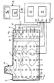
- the glass melting tank 1 is highlighted by a thick outline 2 and has a loading end 3 and a removal end 4, between which a refining bench 5 in the form of a from the tub bottom (container bottom) towering weir is only hinted at as a "deep Refiner "6.
- the loading takes place via a so-called” dog House “7.
- the heat sources, burners and / or electrodes, are the Not shown for the sake of simplicity.
- This measured value detection device 8 has a central control unit 10 with a timer and a memory 11 with a whole row of storage locations that are not particularly shown.
- the memory 11 is used to store all temperature measurements with the associated ones Space coordinates of the temperature measuring probes T1, T2, T3 to Tn too a time to, further storage locations are used for storage analog values at later times t1, t2, t3 to tn, the days, Can be weeks, months or years apart.
- a Bus system B the data is forwarded to a computer 9 which a monitor 9a and a memory 12 with numerous storage spaces owns, which are also not shown individually.
- a temperature field is created by the temperature measuring probes T1, T2, T3 to Tn detected, which is displayed on the monitor 9a and its isotherms are shown in dashed lines.
- the individual areas can also be by the measured value detection device 8 in different colors represent. In areas with close proximity to the isotherms there are steep temperature gradients that indicate a strong local heat load and / or excessive wear of the refractory material of the tub bottom close. If you are now in time-lapse One after the other several, at least two such isothermal representations displays, it immediately becomes apparent which changes at what location and how much wear has already occurred is advanced.
Landscapes
- Chemical & Material Sciences (AREA)
- Physics & Mathematics (AREA)
- General Physics & Mathematics (AREA)
- Engineering & Computer Science (AREA)
- Materials Engineering (AREA)
- Organic Chemistry (AREA)
- Radiation Pyrometers (AREA)
- Waste-Gas Treatment And Other Accessory Devices For Furnaces (AREA)
- Medical Treatment And Welfare Office Work (AREA)
- Medical Preparation Storing Or Oral Administration Devices (AREA)
- Furnace Housings, Linings, Walls, And Ceilings (AREA)
- Optical Measuring Cells (AREA)
Claims (20)
- Procédé pour déterminer des variations de l'état de fonctionnement au niveau de surfaces limites de récipients, guidant une masse fondue, d'installations de fusion du verre, moyennant la détection locale de gradients de température au moyen de sondes de mesure de température, qui sont disposées à l'intérieur des matériaux de construction du récipient tirés du groupe de matériaux réfractaires et d'un isolant thermique et disposées à distance de la surface, côté verre, des matériaux réfractaires et/ou à l'intérieur de l'isolant thermique, selon lequel les valeurs de mesure sont affichées en association avec leurs coordonnées spatiales, et selon lequel on dispose une matrice desdites sondes de mesure de température (T1, T2, T3, ... Tn), on mémorise successivement une suite de données de plusieurs mesures à différents instants dans un calculateur (9) et on interroge successivement les différentes valeurs de mesure de température et les coordonnées spatiales associées à ces mesures à partir du calculateur (9) et on compare entre elles les données correspondant aux différents instants et on détermine à partir de ladite suite de valeurs mesurées de température, dans des représentations optiques accélérées, les variations dans le temps et les variations locales de l'état de fonctionnement.
- Procédé selon la revendication 1, caractérisé en ce qu'on dispose la ou chaque matrice de sondes de mesure de température (T1, T2, T3, ... Tn) à des distances identiques des surfaces, côté verre, des matériaux de construction des récipients.
- Procédé selon la revendication 1, caractérisé en ce qu'on dispose au moins deux matrices de sondes de mesure de température (T1, T2, T3, ... Tn) à des intervalles différents des surfaces, côté verre, des matériaux de construction des récipients.
- Procédé selon la revendication 1, caractérisé en ce qu'on dispose au moins une matrice de sondes de mesure de température (T1, T2, T3, ... Tn) dans le fond des récipients.
- Procédé selon la revendication 1, caractérisé en ce qu'on calcule par interpolation et/ou extrapolation, des valeurs supplémentaires de température à l'intérieur et à l'extérieur de la ou de chaque matrice de sondes de mesure de température (T1, T2, T3, ... Tn) et on les mémorise en association avec leurs coordonnées fictives de distribution de surface.
- Procédé selon la revendication 1, caractérisé en ce qu'on représente la distribution de température au moyen de zones colorées différenciées.
- Procédé selon la revendication 1, caractérisé en ce qu'on représente la distribution de température par des isothermes sous la forme de lignes.
- Procédé selon la revendication 1, caractérisé en ce qu'on mémorise les données pour les températures et les coordonnées spatiales des sondes de mesure de température (T1, T2, T3, ... Tn) et d'éventuelles valeurs d'interpolation de ces données sur un support de données.
- Procédé selon la revendication 1, caractérisé en ce qu'on transmet les données "en ligne".
- Procédé selon la revendication 1, caractérisé en ce qu'on mémorise la suite de données de plusieurs mesures avec les coordonnées spatiales associées et qu'on les représente sur un moniteur (9a) avec une fréquence d'images usuelle pour des appareils à écran (8).
- Procédé selon la revendication 10, caractérisé en ce qu'on transmet la suite d'images "en ligne".
- Procédé selon la revendication 11, caractérisé en ce qu'on réalise une sortie imprimée de la suite de données de plusieurs mesures avec les coordonnées spatiales associées, au moyen d'une imprimante.
- Procédé selon la revendication 1, caractérisé en ce qu'on place un groupe de sondes supplémentaires de mesure de température à l'intérieur de la masse fondue de verre à des distances identiques des sondes de mesure de température (T1, T2, T3, ... Tn) de la matrice disposées à l'extérieur de la masse fondue de verre, et qu'on détermine l'épaisseur de paroi résiduelle respective au moyen d'une comparaison permanente des valeurs de mesure de température de sondes de mesure de température voisines.
- Dispositif de mesure pour la détermination de surfaces limites de récipients guidant une masse fondue, d'installation de fusion du verre par détection locale de gradients de température, et dans lequel plusieurs sondes de mesure de température sont disposées à l'intérieur des matériaux de construction des récipients, qui font partie du groupe des matériaux réfractaires et d'un isolant thermique et à distance de la surface, côté verre, des matériaux réfractaires et/ou à l'intérieur de matériaux isolants, et dans lequel au moins une matrice desdites sondes de mesure de température (T1, T2, T3, ... Tn) est présente, et dans lequel sont prévus un dispositif (8) de détection des valeurs de mesure et un calculateur (9) comportant respectivement au moins une mémoire (11, 12) et une minuterie pourdans lequel il est prévu un circuit de répétition, à l'aide duquel les différentes variations des valeurs de mesure de température peuvent être appelées, et es variations locales de l'état de fonctionnement peuvent être déterminées par comparaison des valeurs de mesure de température, enregistrées à différents instants, selon des représentations optiques accélérées.a) la mémorisation des différentes valeurs de mesure de température en association avec les coordonnées spatiales desdites sondes de mesure de température (T1, T2, T3, ... Tn), et pourb) la mémorisation d'une suite d'autres valeurs de mesure de température desdites sondes de mesure de température (T1, T2, T3, ... Tn) à différents instants en fonction de la minuterie, et
- Dispositif de mesure selon la revendication 14, caractérisé en ce que les valeurs de mesure de température peuvent être représentées sous la forme d'isothermes sur un écran.
- Dispositif de mesure selon la revendication 14, caractérisé en ce que les valeurs de mesure de température peuvent être imprimées sous la forme d'isothermes par une imprimante.
- Dispositif de mesure selon la revendication 14, caractérisé en ce que la ou chaque matrice de sondes de mesure de température (T1, T2, T3, ... Tn) est disposée à des distances identiques des surfaces, côté verre, des matériaux de construction des récipients.
- Dispositif de mesure selon la revendication 14, caractérisé en ce qu'au moins deux matrices de sondes de mesure de température (T1, T2, T3, ... Tn) sont disposées à des distances différentes des surfaces, côté verre, des matériaux de construction des récipients.
- Dispositif de mesure selon la revendication 14, caractérisé en ce que la au moins une matrice de sondes de mesure de température (T1, T2, T3, ... Tn) est disposée du côté d'au moins une surface limite faisant partie du groupe réchauffeurs, fonds de cuves, parois latérales, passages, parties d'épuration et de conditionnement, dispositifs d'alimentation et têtes d'alimentation.
- Dispositif de mesure selon la revendication 14, caractérisé en ce que le calculateur (9) est conçu pour une détermination de valeurs supplémentaires de température à l'intérieur et à l'extérieur de la ou de chaque matrice par interpolation et/ou extrapolation et que la au moins une mémoire (11, 12) comporte des emplacements de mémoire pour ces valeurs supplémentaires de température et pour leurs coordonnées de surface fictives.
Applications Claiming Priority (2)
| Application Number | Priority Date | Filing Date | Title |
|---|---|---|---|
| DE19853785A DE19853785C5 (de) | 1998-11-21 | 1998-11-21 | Verfahren und Meßanordnung zum Bestimmen von Veränderungen des Betriebszustandes von feuerfesten Baustoffen an Glasschmelze führenden Behältern |
| DE19853785 | 1998-11-21 |
Publications (2)
| Publication Number | Publication Date |
|---|---|
| EP1004863A1 EP1004863A1 (fr) | 2000-05-31 |
| EP1004863B1 true EP1004863B1 (fr) | 2002-11-20 |
Family
ID=7888580
Family Applications (1)
| Application Number | Title | Priority Date | Filing Date |
|---|---|---|---|
| EP99121523A Revoked EP1004863B1 (fr) | 1998-11-21 | 1999-10-29 | Procédé et arrangement de mesure pour déterminer les changements opératoires dans des cuves transportant du verre |
Country Status (5)
| Country | Link |
|---|---|
| EP (1) | EP1004863B1 (fr) |
| AT (1) | ATE228240T1 (fr) |
| DE (2) | DE19853785C5 (fr) |
| ES (1) | ES2186288T3 (fr) |
| PT (1) | PT1004863E (fr) |
Families Citing this family (8)
| Publication number | Priority date | Publication date | Assignee | Title |
|---|---|---|---|---|
| DE10031058B4 (de) * | 2000-06-26 | 2012-10-11 | Matthias Franke | Verfahren zur Prozessregelung von Hochtemperaturschmelzanlagen, Hochtemperaturschmelzanlage, sowie Verfahren zum Betreiben einer Hochtemperaturschmelzanlage |
| DE10326612B3 (de) * | 2003-06-13 | 2004-10-21 | Schott Glas | Verfahren zur Messung der Temperatur im Innern eines flüssigen oder festen Mediums |
| DE10328038B4 (de) * | 2003-06-18 | 2005-06-16 | Honarmand, Hossein, Dr. | Verfahren und System zur dynamischen Erfassung von Temperaturverteilungen |
| JP5374521B2 (ja) * | 2009-01-28 | 2013-12-25 | 株式会社アルバック | 温度検出装置、加熱装置、基板加熱方法 |
| EP2407751B1 (fr) | 2010-07-01 | 2015-10-07 | Ingenieurbüro Franke GlasTechnologie-Service | Procédé et dispositif de détermination informatique de l'épaisseur restante d'au moins une paroi d'un récipient |
| DE102014010820B4 (de) * | 2013-07-23 | 2017-11-30 | SAUKE.SEMRAU GmbH | Verfahren zum Betreiben eines Schmelz- und/oder Warmhalteofens und Schmelzofen |
| CN108955944B (zh) * | 2018-05-16 | 2022-04-05 | 洛阳北方玻璃技术股份有限公司 | 一种用于玻璃钢化炉中的测温探头安装位置的选取方法 |
| FR3084661B1 (fr) * | 2018-08-01 | 2021-01-22 | Saint Gobain Ct Recherches | Four de verrerie pourvu de fibres optiques |
Family Cites Families (9)
| Publication number | Priority date | Publication date | Assignee | Title |
|---|---|---|---|---|
| DD240538A1 (de) * | 1985-08-26 | 1986-11-05 | Glasindustrie Waermetech Inst | Wannenbeckenwand fuer oefen zum schmelzen von glas oder aehnlichen stoffen |
| US4737917A (en) * | 1986-07-15 | 1988-04-12 | Emhart Industries, Inc. | Method and apparatus for generating isotherms in a forehearth temperature control system |
| US4823290A (en) * | 1987-07-21 | 1989-04-18 | Honeywell Bull Inc. | Method and apparatus for monitoring the operating environment of a computer system |
| US4875176A (en) * | 1987-10-22 | 1989-10-17 | Curtis L. Harsch | Method and apparatus for measuring surface temperatures |
| US5158366A (en) * | 1989-05-31 | 1992-10-27 | Kabushiki Kaisha Kobe Seiko Sho | Refractory monitoring temperature sensor and refractory erosion location measuring device |
| DE4039601A1 (de) * | 1990-12-12 | 1992-06-17 | Sorg Gmbh & Co Kg | Schmelzwanne fuer glas-wannenoefen mit palisadensteinen und betriebsverfahren hierfuer |
| US5067977A (en) * | 1991-02-05 | 1991-11-26 | Libbey-Owens-Ford Co. | Method and apparatus for measuring the efficiency of cooling devices |
| JPH07142417A (ja) * | 1993-11-22 | 1995-06-02 | Sony Corp | 炉内温度監視装置 |
| BE1008987A3 (fr) * | 1995-01-06 | 1996-10-01 | Robyn Pierre | Blocs refractaires a canalisations pour sols de fours verriers et installation dans les sols de circuits de refroidissement ou de chauffage, permettant d'ameliorer le controle thermique des sols et la qualite du verre. |
-
1998
- 1998-11-21 DE DE19853785A patent/DE19853785C5/de not_active Expired - Fee Related
-
1999
- 1999-10-29 ES ES99121523T patent/ES2186288T3/es not_active Expired - Lifetime
- 1999-10-29 AT AT99121523T patent/ATE228240T1/de not_active IP Right Cessation
- 1999-10-29 PT PT99121523T patent/PT1004863E/pt unknown
- 1999-10-29 EP EP99121523A patent/EP1004863B1/fr not_active Revoked
- 1999-10-29 DE DE59903459T patent/DE59903459D1/de not_active Expired - Fee Related
Also Published As
| Publication number | Publication date |
|---|---|
| DE19853785C2 (de) | 2002-06-20 |
| DE59903459D1 (de) | 2003-01-02 |
| ATE228240T1 (de) | 2002-12-15 |
| DE19853785A1 (de) | 2000-05-25 |
| EP1004863A1 (fr) | 2000-05-31 |
| PT1004863E (pt) | 2003-03-31 |
| DE19853785C5 (de) | 2004-10-07 |
| ES2186288T3 (es) | 2003-05-01 |
Similar Documents
| Publication | Publication Date | Title |
|---|---|---|
| EP1004863B1 (fr) | Procédé et arrangement de mesure pour déterminer les changements opératoires dans des cuves transportant du verre | |
| DE69018863T2 (de) | Durchbruch-Feststellung beim Stranggiessen. | |
| DE69321160T2 (de) | Verfahren und Gerät zur Anzeige der Temperatur eines Hochofens und ein, ein solches Temperaturanzeigegerät benutzendes Temperaturüberwachungssystem | |
| EP2312250B1 (fr) | Récipient métallurgique | |
| DE69720456T2 (de) | Verfahren zur steuerung des löschens von koks in einem koksbehälter | |
| EP3385007A1 (fr) | Dispositif à pièce d'usure et dispositif de mesure d'usure | |
| DE69307158T2 (de) | Verfahren und Vorrichtung zur Bestimmung der Dicke der Feuerfeststoffebeschichtung in einem Behälter für schmelzflüssiges Metall und zum Nachweis von durchdringendem Metall in der Beschichtung | |
| EP1835279A2 (fr) | Procédé et dispositif de mesure destinés à la détermination de la conductivité thermique du matériau ignifuge d'un revêtement de four réfractaire | |
| DE3822705C2 (fr) | ||
| DE3341630C2 (fr) | ||
| DE102006046987A1 (de) | Glasflaschenprüfmaschine | |
| EP1655570B1 (fr) | Procédé destiné à la mesure géométrique optique d'une cavité dans une installation de traitement thermique | |
| DE10244826B4 (de) | Anordnung zur Überwachung des Verschleißzustandes der Feuerfestauskleidung von Schmelzwannen, insbesondere von Glasschmelzwannen | |
| DE3026297C2 (fr) | ||
| DE4342498C2 (de) | Verfahren und Einrichtung zur Regelung der Position der Spitze einer Elektroofen-Elektrode | |
| DE3017374C1 (de) | Vorrichtung zur Herstellung von Glasfasern | |
| DE3042103C2 (de) | Verfahren und Vorrichtung zum Messen des Höhenverlaufs der Schmelzzone in einem Hochofen | |
| DE4237872C2 (de) | Verfahren und Rottezelle zur Überwachung der Desinfektion von kompostierfähigen Abfall | |
| DE69807025T2 (de) | Verfahren und Giessanlage zur Erzeugung von Dünnbändern auf einer oder zwischen zwei Rollen | |
| DE10160823A1 (de) | Meßverfahren für Gemengebedeckung und Glasrückstrom bei Glasschmelzwannen mittels Ofenraumkamera | |
| WO2005084844A1 (fr) | Procede de preparation de donnees de surface, procede et dispositif d'evaluation de qualite et de gestion de qualite d'un materiau en bande | |
| DE219329C (fr) | ||
| DE570758C (de) | Verfahren zur UEberwachung des Hochofens | |
| EP1849752B1 (fr) | Procédé destiné au contrôle d'un état de fonctionnement instable dans une installation de traitement thermique | |
| DE454643C (de) | Verfahren und Vorrichtung zum Auszieben einer endlosen Glastafel aus dem Spiegel dergeschmolzenen Masse |
Legal Events
| Date | Code | Title | Description |
|---|---|---|---|
| PUAI | Public reference made under article 153(3) epc to a published international application that has entered the european phase |
Free format text: ORIGINAL CODE: 0009012 |
|
| AK | Designated contracting states |
Kind code of ref document: A1 Designated state(s): AT BE CH CY DE DK ES FI FR GB GR IE IT LI LU MC NL PT SE |
|
| AX | Request for extension of the european patent |
Free format text: AL;LT;LV;MK;RO;SI |
|
| 17P | Request for examination filed |
Effective date: 20000923 |
|
| AKX | Designation fees paid |
Free format text: AT BE CH CY DE DK ES FI FR GB GR IE IT LI LU MC NL PT SE |
|
| 17Q | First examination report despatched |
Effective date: 20011127 |
|
| GRAG | Despatch of communication of intention to grant |
Free format text: ORIGINAL CODE: EPIDOS AGRA |
|
| GRAG | Despatch of communication of intention to grant |
Free format text: ORIGINAL CODE: EPIDOS AGRA |
|
| GRAH | Despatch of communication of intention to grant a patent |
Free format text: ORIGINAL CODE: EPIDOS IGRA |
|
| GRAH | Despatch of communication of intention to grant a patent |
Free format text: ORIGINAL CODE: EPIDOS IGRA |
|
| GRAA | (expected) grant |
Free format text: ORIGINAL CODE: 0009210 |
|
| AK | Designated contracting states |
Kind code of ref document: B1 Designated state(s): AT BE CH CY DE DK ES FI FR GB GR IE IT LI LU MC NL PT SE |
|
| PG25 | Lapsed in a contracting state [announced via postgrant information from national office to epo] |
Ref country code: NL Free format text: LAPSE BECAUSE OF FAILURE TO SUBMIT A TRANSLATION OF THE DESCRIPTION OR TO PAY THE FEE WITHIN THE PRESCRIBED TIME-LIMIT Effective date: 20021120 Ref country code: IE Free format text: LAPSE BECAUSE OF FAILURE TO SUBMIT A TRANSLATION OF THE DESCRIPTION OR TO PAY THE FEE WITHIN THE PRESCRIBED TIME-LIMIT Effective date: 20021120 Ref country code: GR Free format text: LAPSE BECAUSE OF FAILURE TO SUBMIT A TRANSLATION OF THE DESCRIPTION OR TO PAY THE FEE WITHIN THE PRESCRIBED TIME-LIMIT Effective date: 20021120 Ref country code: FI Free format text: LAPSE BECAUSE OF FAILURE TO SUBMIT A TRANSLATION OF THE DESCRIPTION OR TO PAY THE FEE WITHIN THE PRESCRIBED TIME-LIMIT Effective date: 20021120 |
|
| REF | Corresponds to: |
Ref document number: 228240 Country of ref document: AT Date of ref document: 20021215 Kind code of ref document: T |
|
| REG | Reference to a national code |
Ref country code: GB Ref legal event code: FG4D Free format text: NOT ENGLISH |
|
| REG | Reference to a national code |
Ref country code: CH Ref legal event code: EP |
|
| REG | Reference to a national code |
Ref country code: IE Ref legal event code: FG4D Free format text: GERMAN |
|
| REF | Corresponds to: |
Ref document number: 59903459 Country of ref document: DE Date of ref document: 20030102 |
|
| GBT | Gb: translation of ep patent filed (gb section 77(6)(a)/1977) |
Effective date: 20030106 |
|
| PG25 | Lapsed in a contracting state [announced via postgrant information from national office to epo] |
Ref country code: SE Free format text: LAPSE BECAUSE OF FAILURE TO SUBMIT A TRANSLATION OF THE DESCRIPTION OR TO PAY THE FEE WITHIN THE PRESCRIBED TIME-LIMIT Effective date: 20030220 Ref country code: DK Free format text: LAPSE BECAUSE OF FAILURE TO SUBMIT A TRANSLATION OF THE DESCRIPTION OR TO PAY THE FEE WITHIN THE PRESCRIBED TIME-LIMIT Effective date: 20030220 |
|
| REG | Reference to a national code |
Ref country code: PT Ref legal event code: SC4A Free format text: AVAILABILITY OF NATIONAL TRANSLATION Effective date: 20030129 |
|
| NLV1 | Nl: lapsed or annulled due to failure to fulfill the requirements of art. 29p and 29m of the patents act | ||
| REG | Reference to a national code |
Ref country code: ES Ref legal event code: FG2A Ref document number: 2186288 Country of ref document: ES Kind code of ref document: T3 |
|
| ET | Fr: translation filed | ||
| REG | Reference to a national code |
Ref country code: IE Ref legal event code: FD4D Ref document number: 1004863E Country of ref document: IE |
|
| PLBQ | Unpublished change to opponent data |
Free format text: ORIGINAL CODE: EPIDOS OPPO |
|
| PLBI | Opposition filed |
Free format text: ORIGINAL CODE: 0009260 |
|
| PLAX | Notice of opposition and request to file observation + time limit sent |
Free format text: ORIGINAL CODE: EPIDOSNOBS2 |
|
| 26 | Opposition filed |
Opponent name: SCHOTT GLAS Effective date: 20030819 |
|
| PG25 | Lapsed in a contracting state [announced via postgrant information from national office to epo] |
Ref country code: LU Free format text: LAPSE BECAUSE OF NON-PAYMENT OF DUE FEES Effective date: 20031029 Ref country code: CY Free format text: LAPSE BECAUSE OF FAILURE TO SUBMIT A TRANSLATION OF THE DESCRIPTION OR TO PAY THE FEE WITHIN THE PRESCRIBED TIME-LIMIT Effective date: 20031029 |
|
| PG25 | Lapsed in a contracting state [announced via postgrant information from national office to epo] |
Ref country code: MC Free format text: LAPSE BECAUSE OF NON-PAYMENT OF DUE FEES Effective date: 20031031 Ref country code: LI Free format text: LAPSE BECAUSE OF NON-PAYMENT OF DUE FEES Effective date: 20031031 Ref country code: CH Free format text: LAPSE BECAUSE OF NON-PAYMENT OF DUE FEES Effective date: 20031031 |
|
| PLBB | Reply of patent proprietor to notice(s) of opposition received |
Free format text: ORIGINAL CODE: EPIDOSNOBS3 |
|
| REG | Reference to a national code |
Ref country code: CH Ref legal event code: PL |
|
| PGFP | Annual fee paid to national office [announced via postgrant information from national office to epo] |
Ref country code: GB Payment date: 20070921 Year of fee payment: 9 |
|
| PLAB | Opposition data, opponent's data or that of the opponent's representative modified |
Free format text: ORIGINAL CODE: 0009299OPPO |
|
| PGFP | Annual fee paid to national office [announced via postgrant information from national office to epo] |
Ref country code: IT Payment date: 20070911 Year of fee payment: 9 Ref country code: ES Payment date: 20071010 Year of fee payment: 9 |
|
| R26 | Opposition filed (corrected) |
Opponent name: SCHOTT AG Effective date: 20030819 |
|
| PGFP | Annual fee paid to national office [announced via postgrant information from national office to epo] |
Ref country code: AT Payment date: 20071025 Year of fee payment: 9 |
|
| APBP | Date of receipt of notice of appeal recorded |
Free format text: ORIGINAL CODE: EPIDOSNNOA2O |
|
| PGFP | Annual fee paid to national office [announced via postgrant information from national office to epo] |
Ref country code: BE Payment date: 20071031 Year of fee payment: 9 |
|
| APAH | Appeal reference modified |
Free format text: ORIGINAL CODE: EPIDOSCREFNO |
|
| PGFP | Annual fee paid to national office [announced via postgrant information from national office to epo] |
Ref country code: FR Payment date: 20070822 Year of fee payment: 9 |
|
| APBQ | Date of receipt of statement of grounds of appeal recorded |
Free format text: ORIGINAL CODE: EPIDOSNNOA3O |
|
| BERE | Be: lapsed |
Owner name: *BETEILIGUNGEN SORG G.M.B.H. & CO. K.G. Effective date: 20081031 |
|
| REG | Reference to a national code |
Ref country code: PT Ref legal event code: MM4A Free format text: LAPSE DUE TO NON-PAYMENT OF FEES Effective date: 20090429 |
|
| PGFP | Annual fee paid to national office [announced via postgrant information from national office to epo] |
Ref country code: DE Payment date: 20081215 Year of fee payment: 10 |
|
| GBPC | Gb: european patent ceased through non-payment of renewal fee |
Effective date: 20081029 |
|
| REG | Reference to a national code |
Ref country code: FR Ref legal event code: ST Effective date: 20090630 |
|
| PG25 | Lapsed in a contracting state [announced via postgrant information from national office to epo] |
Ref country code: PT Free format text: LAPSE BECAUSE OF NON-PAYMENT OF DUE FEES Effective date: 20090429 Ref country code: IT Free format text: LAPSE BECAUSE OF NON-PAYMENT OF DUE FEES Effective date: 20081029 Ref country code: AT Free format text: LAPSE BECAUSE OF NON-PAYMENT OF DUE FEES Effective date: 20081029 |
|
| PG25 | Lapsed in a contracting state [announced via postgrant information from national office to epo] |
Ref country code: BE Free format text: LAPSE BECAUSE OF NON-PAYMENT OF DUE FEES Effective date: 20081031 |
|
| PG25 | Lapsed in a contracting state [announced via postgrant information from national office to epo] |
Ref country code: FR Free format text: LAPSE BECAUSE OF NON-PAYMENT OF DUE FEES Effective date: 20081031 |
|
| PG25 | Lapsed in a contracting state [announced via postgrant information from national office to epo] |
Ref country code: GB Free format text: LAPSE BECAUSE OF NON-PAYMENT OF DUE FEES Effective date: 20081029 |
|
| PGFP | Annual fee paid to national office [announced via postgrant information from national office to epo] |
Ref country code: PT Payment date: 20070823 Year of fee payment: 9 |
|
| REG | Reference to a national code |
Ref country code: ES Ref legal event code: FD2A Effective date: 20081030 |
|
| PG25 | Lapsed in a contracting state [announced via postgrant information from national office to epo] |
Ref country code: ES Free format text: LAPSE BECAUSE OF NON-PAYMENT OF DUE FEES Effective date: 20081030 |
|
| PG25 | Lapsed in a contracting state [announced via postgrant information from national office to epo] |
Ref country code: DE Free format text: LAPSE BECAUSE OF NON-PAYMENT OF DUE FEES Effective date: 20100501 |
|
| APBU | Appeal procedure closed |
Free format text: ORIGINAL CODE: EPIDOSNNOA9O |
|
| RDAF | Communication despatched that patent is revoked |
Free format text: ORIGINAL CODE: EPIDOSNREV1 |
|
| RDAG | Patent revoked |
Free format text: ORIGINAL CODE: 0009271 |
|
| STAA | Information on the status of an ep patent application or granted ep patent |
Free format text: STATUS: PATENT REVOKED |
|
| 27W | Patent revoked |
Effective date: 20080114 |