EP1004871A2 - Vorrichtung und Verfahren zur Probenanalyse - Google Patents
Vorrichtung und Verfahren zur Probenanalyse Download PDFInfo
- Publication number
- EP1004871A2 EP1004871A2 EP99309431A EP99309431A EP1004871A2 EP 1004871 A2 EP1004871 A2 EP 1004871A2 EP 99309431 A EP99309431 A EP 99309431A EP 99309431 A EP99309431 A EP 99309431A EP 1004871 A2 EP1004871 A2 EP 1004871A2
- Authority
- EP
- European Patent Office
- Prior art keywords
- flow
- trap
- sensor device
- gas
- sample tube
- Prior art date
- Legal status (The legal status is an assumption and is not a legal conclusion. Google has not performed a legal analysis and makes no representation as to the accuracy of the status listed.)
- Withdrawn
Links
- 238000000034 method Methods 0.000 title claims abstract description 19
- 239000000126 substance Substances 0.000 claims abstract description 68
- 239000007789 gas Substances 0.000 claims abstract description 39
- 239000011261 inert gas Substances 0.000 claims abstract description 35
- 239000002594 sorbent Substances 0.000 claims abstract description 34
- 238000010438 heat treatment Methods 0.000 claims abstract description 20
- 238000004458 analytical method Methods 0.000 claims abstract description 10
- 239000000463 material Substances 0.000 claims abstract description 8
- 238000001816 cooling Methods 0.000 claims description 4
- 230000008859 change Effects 0.000 claims description 3
- 230000003247 decreasing effect Effects 0.000 claims description 2
- 238000001514 detection method Methods 0.000 claims description 2
- 238000009792 diffusion process Methods 0.000 claims description 2
- 230000008878 coupling Effects 0.000 description 20
- 238000010168 coupling process Methods 0.000 description 20
- 238000005859 coupling reaction Methods 0.000 description 20
- 239000013078 crystal Substances 0.000 description 2
- 238000003795 desorption Methods 0.000 description 2
- 238000010586 diagram Methods 0.000 description 2
- 230000002035 prolonged effect Effects 0.000 description 2
- 239000010453 quartz Substances 0.000 description 2
- 230000004044 response Effects 0.000 description 2
- 238000005070 sampling Methods 0.000 description 2
- VYPSYNLAJGMNEJ-UHFFFAOYSA-N silicon dioxide Inorganic materials O=[Si]=O VYPSYNLAJGMNEJ-UHFFFAOYSA-N 0.000 description 2
- 239000002250 absorbent Substances 0.000 description 1
- 230000002745 absorbent Effects 0.000 description 1
- 239000003463 adsorbent Substances 0.000 description 1
- 230000008901 benefit Effects 0.000 description 1
- 238000000576 coating method Methods 0.000 description 1
- 230000001010 compromised effect Effects 0.000 description 1
- 239000012141 concentrate Substances 0.000 description 1
- 238000010276 construction Methods 0.000 description 1
- 239000003344 environmental pollutant Substances 0.000 description 1
- 235000013305 food Nutrition 0.000 description 1
- 238000003780 insertion Methods 0.000 description 1
- 230000037431 insertion Effects 0.000 description 1
- 238000005259 measurement Methods 0.000 description 1
- 239000000203 mixture Substances 0.000 description 1
- 238000005192 partition Methods 0.000 description 1
- 239000004033 plastic Substances 0.000 description 1
- 229920003023 plastic Polymers 0.000 description 1
- 231100000719 pollutant Toxicity 0.000 description 1
- 230000008569 process Effects 0.000 description 1
- 238000010926 purge Methods 0.000 description 1
- 230000009467 reduction Effects 0.000 description 1
- 230000035945 sensitivity Effects 0.000 description 1
- 239000000758 substrate Substances 0.000 description 1
- 229920002994 synthetic fiber Polymers 0.000 description 1
- XLYOFNOQVPJJNP-UHFFFAOYSA-N water Substances O XLYOFNOQVPJJNP-UHFFFAOYSA-N 0.000 description 1
Images


Classifications
-
- G—PHYSICS
- G01—MEASURING; TESTING
- G01N—INVESTIGATING OR ANALYSING MATERIALS BY DETERMINING THEIR CHEMICAL OR PHYSICAL PROPERTIES
- G01N1/00—Sampling; Preparing specimens for investigation
- G01N1/28—Preparing specimens for investigation including physical details of (bio-)chemical methods covered elsewhere, e.g. G01N33/50, C12Q
- G01N1/40—Concentrating samples
- G01N1/405—Concentrating samples by adsorption or absorption
-
- G—PHYSICS
- G01—MEASURING; TESTING
- G01N—INVESTIGATING OR ANALYSING MATERIALS BY DETERMINING THEIR CHEMICAL OR PHYSICAL PROPERTIES
- G01N30/00—Investigating or analysing materials by separation into components using adsorption, absorption or similar phenomena or using ion-exchange, e.g. chromatography or field flow fractionation
- G01N30/02—Column chromatography
- G01N30/04—Preparation or injection of sample to be analysed
- G01N30/06—Preparation
- G01N30/12—Preparation by evaporation
- G01N2030/121—Preparation by evaporation cooling; cold traps
Definitions
- the present invention relates to a method and apparatus for analysing samples which have been taken of substances present in a vapour.
- sample tubes containing adsorbent or absorbent material
- sample tubes may be used to sample for pollutants in the air e.g. at a person's workstation, or to sample vapours given off by food products or by natural or synthetic materials (e.g. plastics materials).
- the sorbent material in the sample tube adsorbs or absorbs volatile substances from the air or other vapour in which the sample tube is placed for a predetermined period of time: the sample tube is then taken to a laboratory for analysis.
- the analytical apparatus which is used is arranged to liberate the adsorbed or absorbed substances by rapidly heating the sample tube to a high temperature whilst a flow of inert gas is passed through the tube: the flow of inert gas carries the liberated substances to an analysing device.
- the analysing device may comprise a chemical sensor device, having a cell of relatively small volume in which one or more chemical sensors are positioned.
- the device may comprise an array of sensors, the sensors of which have different response characteristics to each of a range of vapours: the pattern or combination of output signals derived from the set of sensors is characteristic of the vapour (or substance carried in an inert gas) to which the sensors are all simultaneously exposed.
- Such sensor devices have the advantage that they can provide information about a sample in a much shorter period of time than other equipment, e.g. gas chromatographs.
- the application of chemical sensor devices is limited by relatively poor signal-to-noise ratios.
- the signal can be increased relative to the noise by extending the duration of time over which the sensor is exposed to the sample being sensed, so allowing more measurements to be made.
- an analytical method which comprises passing a first flow of inert gas through a sample tube and a trap in succession whilst said sample tube is heated and said trap is cooled, the sample tube containing sorbent material on which one or more volatile substances have been adsorbed or absorbed and said trap containing a smaller quantity of material serving to adsorb or absorb the volatile substance(s) liberated from the sample tube, and subsequently passing a second flow of inert gas through said trap and a sensor device in succession whilst heating said trap.
- the sample tube is heated to liberate the volatile substance(s) previously adsorbed or absorbed on its sorbent material (typically of 200mg): the volatile substances are carried by the flow of inert gas to the trap, the sorbent material (typically 20mg) of which adsorbs or absorbs the volatile substances carried by the inert gas.
- the sample tube will have been used at ambient temperature to sample a vapour and adsorb or absorb the volatile substances in that vapour: because the trap device is now cooled to below ambient temperature (e.g. to-10°C), its smaller quantity of sorbent material is able to take up all of the volatile substances liberated from the sample tube.
- the trap (typically in the form of a tube similar to but of smaller size than the sample tube) would not be useful as the sample tube itself, because at ambient temperature its small quantity of sorbent material is only capable of retaining substances from a limited volume of gas before "break through", i.e. the volatile substances start to diffuse out through the opposite end of the tube from the entry end: for example, 20mg of sorbent material is only able to take up substances from a maximum of 1 litre of gas before break through; the small amount of volatile substance which can be taken up from the ambient by such a small tube limits the signal obtainable from the sensor device during analysis.
- the larger sample tube with typically 200mg of sorbent material, is therefore required to take the sample at ambient temperature: however, the method of the present invention then effectively transfers this sample to the smaller trap: because of the much lower temperature, the affinity of its sorbent material is much increased; typically, 20mg of sorbent material at -10°C is able to retain the volatile substance from up to 10 litres of gas without break through.
- the trap is heated to liberate the volatile substances which have been transferred to it from the sample tube, and the flow of insert gas carries these liberated substances to the sensor device. Because of its relatively small size, the trap can be heated more rapidly than the sample tube, such that the volatile substances are liberated into a relatively small volume of gas: typically, 20mg of sorbent material can be heated at a rate of 60°C/sec to liberate substances ranging in volatility from n-C5 to n-C40 into a volume of approximately 1.0 to 1.5ml of gas. Thus, the liberated substances are concentrated into a small volume of the gas flow, which volume is typically of the same order of magnitude as the cell volume of the sensor device.
- the sample may be desirable to transfer the sample from the sample tube to a first trap, then from that trap to a smaller trap, and possibly from the second trap to a further trap and so on, before in a final stage the sample is passed to the sensor device.
- the sample is successively concentrated into progressively smaller volumes of sorbent material, until the volume of gas into which the sample substances can be liberated matches the cell volume of the sensor device.
- an analytical apparatus which comprises means for heating a sample tube which contains sorbent material, a trap which contains a smaller quantity of sorbent material, means for establishing a first flow of inert gas through said sample tube and trap in succession, means for establishing a second flow of inert gas through said trap and through a sensor device in succession, and means for cooling said trap whilst said first flow of inert gas is established and for heating said trap whilst said second flow of inert gas is established.
- the apparatus may be arranged to perform a two-stage or multiple-stage transfer, successively concentrating the sample onto progressively smaller traps.
- the sensor output signal describes a relatively sharp peak, the duration of which is short. For example, a sample volume of lml carried in a gas flow of 2ml/min will pass through the sensor device in 30 seconds. There are accordingly problems of inadequate signal-to-noise ratio.
- an analytical method which comprises passing a flow of inert gas through a body of sorbent material and through a sensor device in succession, heating the sorbent material to liberate, into a volume of flowing gas, any volatile substance or substances previously taken up by said sorbent material, and stopping said flow of inert gas at a predetermined instant after commencing heating the sorbent material, corresponding to the presence of said volume of gas in said sensor device.
- the flow of gas is stopped when the liberated sample substances are present within the sensor device: this extends the time for which the sensor device is exposed to the sample substances and so extends the duration of the corresponding output signal or signals of the sensor device; the signals of interest are accordingly easier to distinguish from noise.
- the instant at which the gas flow is stopped may be determined from a knowledge of the rate of flow of the gas and the volume of the flow path to the sensor device.
- means may be provided for responding to a change in the sensor output signal, indicating detection of the sample substance within the sensor cell, to stop the gas flow: such an arrangement automatically compensates for changes in flow or other factors affecting the delay between commencement of heating and arrival of the sample substances within the sensor device.
- the diffusion of the sample out of the sensor device may be sufficiently restricted simply by providing the sensor device with an outlet passage which has a width relatively small compared with its length.
- the gas flow is restarted in order to flush the sample volume out of the sensor device.
- the sample flushed out of the sensor device may be collected (e.g. adsorbed or absorbed in a further sample tube) for subsequent analysis.
- an analytical apparatus which comprises means for heating a device which contains sorbent material in order to liberate any volatile substance or substances previously taken up thereby, a sensor device, and means for establishing a flow of inert gas through said sorbent material and said sensor device in succession, the apparatus being arranged to terminate said flow of inert gas a predetermined time after commencement of heating said material.
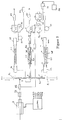
- an analytical apparatus which comprises a chemical sensor array device D for analysing substances released from a sample tube ST by thermal desorption.
- the sample tube ST is filled with granular sorbent material 10, held in place by gas-permeable partitions 12,14 inset from the respective ends of the sample tube: the sample tube ST has been used to take a sample at ambient temperature, its sorbent material 10 adsorbing or absorbing any volatile substances at the sampling location.
- the analytical apparatus comprises two couplings 22,24 for receiving the opposite ends of the sample tube ST: coupling 22 is fixed and the other coupling 24 is retractable to allow the sample tube ST to be inserted for desorption, and subsequently removed.
- a source IG of inert gas is connected to an input coupling 26 which is connected via a solenoid valve SV4 and a flexible link 27 to the retractable coupling 24: the flexible link 27 allows the line leading to the coupling 24 to accommodate the retraction of this coupling.
- the opposite coupling 22 for the sample tube ST is connected to an inlet port 1 of a control valve 30: this control valve comprises a tubular body formed with a number of ports 1 to 3 at different positions along its length, and plungers P1, P2 slidably inserted into the opposite ends of the tubular valve body; the plungers P1, P2 are linked together so that as one plunger is advanced into the valve body, the other plunger is retracted.
- the inlet port 1 from the sample tube ST is positioned adjacent one end of the valve body 30: an outlet port 3 adjacent the opposite end of the valve body is connected via a condenser device 32 (a so-called "cold finger” device) to the sensor array device D.
- the inlet IN of the solenoid valve SV4 is connected via a solenoid valve SV1 (and a first outlet O, thereof) and a flow reducing coupling 34 to a tee coupling 35 on the line between the control valve 30 and the condenser device 32.
- the same outlet port 2 is connected to a flow path in which a secondary sample tube FT may be connected, via couplings 36,38.
- the trap tube TT contains granular sorbent material 39, but is substantially smaller in size and contains a substantially smaller quantity of sorbent material than the sample tube ST (typically 20mg as compared with 200mg).
- the opposite end of the trap tube TT is connected via a solenoid valve SV3 and a needle valve 40 (acting as an adjustable restrictor) to a vent.
- a second outlet O 2 of the solenoid valve SV1 is also connected to the inlet of solenoid valve SV3.
- the secondary sample tube FT is of the same construction and size as the sample tube ST.
- the coupling 38 is arranged for engaging the opposite end of the secondary tube FT from the coupling 36: coupling 38 is connected via a flexible link 42 (which accommodates retraction of the coupling 38 for insertion/removal of the filter tube) to a solenoid valve SV2, the outlet of which is connected via a needle valve 44 to a vent.
- a pressure transducer PT is connected to a tee coupling 46 in the inlet line to the solenoid valve SV4.
- the apparatus further comprises a control means CONTROL for controlling the valves SV1 to SV4, the plungers P1,P2 of the valve body 30, and heating means 48 and 52 and cooling means 50 which are associated with the sample tube ST and trap tube TT: the control means also responds to one or more output signals from the sensor array device D.
- CONTROL for controlling the valves SV1 to SV4, the plungers P1,P2 of the valve body 30, and heating means 48 and 52 and cooling means 50 which are associated with the sample tube ST and trap tube TT: the control means also responds to one or more output signals from the sensor array device D.
- inert gas from the source IG flows through the solenoid valve SV1, the flow restrictor 34, tee coupling 35, the condenser 32 and the sensor array device D, in order to purge the sensor array device D.
- the condenser 32 serves to remove water or other substances which would otherwise condense within the sensor array device D.
- the solenoid valve SV4 is closed to prevent the flow of gas to the coupling 24 for the sample tube ST: also the control valve plunger P1 is inserted into the valve body 30 to close the path from the sample tube end coupling 22; any previous sample tube can be removed and a new sample tube ST inserted.
- solenoid valves SV2 and SV3 are however closed, such that the trap tube TT and secondary sample tube FT merely fill with inert gas.
- solenoid valve SV4 is opened and plunger P1 retracted (and plunger P2 inserted), for gas to flow into the sample tube ST: the system is then monitored for leaks over a predetermined period of time, a leak being indicated by any reduction in the pressure sensed by the pressure transducer PT.
- the sample tube ST is purged by opening the solenoid valves SV2 and SV3 to allow the flow of inert gas through the sample tube ST, the control valve 30 and the trap tube TT and secondary sample tube FT.
- the substances previously taken up by the sample tube ST are now transferred to the trap tube TT.
- the sample tube ST is heated by heating means 48 to liberate the adsorbed or absorbed volatile substances, to be carried by the flow of inert gas to the trap tube TT: the latter tube is cooled e.g. to -10°C by cooling means 50 in order to maximise its ability to take up the volatile substances from the gas flowing through it.
- the solenoid valve SV2 may be closed to prevent the flow of gas through, and transfer of volatile substances to, the secondary tube FT: if desired, however, the solenoid valve SV2 may be open so that a proportion of the inert gas flow passes through the secondary tube FT and a corresponding proportion of the volatile substances, liberated from the sample tube ST, are transferred to the secondary tube FT.
- a series of traps T1 to T3 of decreasing volume are provided, as shown diagrammatically in Figure 2, through which a sample may be passed in succession to progressively concentrate the sample within the flow of gas.
- the sensor array device D comprises a cell of small volume, through which the flow of gas passes.
- the device comprises a substrate, positioned within the cell, which is formed with an array of e.g. six sensors, which have different sensitivities to specific substances.
- the device may comprise a microbalance device, in which the sensors comprise quartz crystals connected in respective resonant circuits: the quartz crystals are coated with different materials, which adsorb or absorb volatile substances to which they are exposed, so altering the weight of the respective coatings and so altering the oscillating frequency of the respective resonant circuits in which they are connected.
- Figure 3 shows a typical set of output signals derived from the sensors of such a device, in use of the apparatus of Figure 1: these output signals represent the change, over time, in the operating frequency of the respective resonant circuits.
- the flow of gas through the trap tube TT is stopped at a predetermined instant corresponding to the arrival, into the sensor cell of device D, of the substances liberated from the trap tube TT.
- These substances therefore remain within the sensor cell for a prolonged period of time, such that the output signals from the respective sensors persist for a correspondingly prolonged period, as shown in Figure 4.
- the system is then returned to the standby mode, during which the sample tube ST can be removed and replaced by a fresh sample tube: also, the secondary sample tube FT can be removed for further analysis, and replaced by a tube which is free of adsorbed or absorbed substances.
Landscapes
- Physics & Mathematics (AREA)
- Health & Medical Sciences (AREA)
- Life Sciences & Earth Sciences (AREA)
- Chemical & Material Sciences (AREA)
- Analytical Chemistry (AREA)
- Biochemistry (AREA)
- General Health & Medical Sciences (AREA)
- General Physics & Mathematics (AREA)
- Immunology (AREA)
- Pathology (AREA)
- Sampling And Sample Adjustment (AREA)
Applications Claiming Priority (2)
| Application Number | Priority Date | Filing Date | Title |
|---|---|---|---|
| GBGB9825806.4A GB9825806D0 (en) | 1998-11-26 | 1998-11-26 | Sample analysing method and apparatus |
| GB9825806 | 1998-11-26 |
Publications (2)
| Publication Number | Publication Date |
|---|---|
| EP1004871A2 true EP1004871A2 (de) | 2000-05-31 |
| EP1004871A3 EP1004871A3 (de) | 2002-04-10 |
Family
ID=10843006
Family Applications (1)
| Application Number | Title | Priority Date | Filing Date |
|---|---|---|---|
| EP99309431A Withdrawn EP1004871A3 (de) | 1998-11-26 | 1999-11-25 | Vorrichtung und Verfahren zur Probenanalyse |
Country Status (2)
| Country | Link |
|---|---|
| EP (1) | EP1004871A3 (de) |
| GB (2) | GB9825806D0 (de) |
Cited By (4)
| Publication number | Priority date | Publication date | Assignee | Title |
|---|---|---|---|---|
| WO2004051227A1 (en) * | 2002-11-30 | 2004-06-17 | Markes International Limited | Automatic thermal desorption apparatus and method |
| RU2697572C1 (ru) * | 2018-10-12 | 2019-08-15 | Закрытое акционерное общество Специальное конструкторское бюро "Хроматэк" | Устройство ввода пробы в анализатор состава |
| RU2697575C1 (ru) * | 2018-05-03 | 2019-08-15 | Общество с ограниченной ответственностью "КимТэк" | Устройство подготовки пробы для анализа примесей малолетучих полярных веществ в жидких средах |
| RU2720656C1 (ru) * | 2019-11-12 | 2020-05-12 | Общество с ограниченной ответственностью «КимТэк» | Способ твердофазного концентрирования комбинации водорастворимых летучих и нелетучих пластовых индикаторов |
Families Citing this family (3)
| Publication number | Priority date | Publication date | Assignee | Title |
|---|---|---|---|---|
| DE10035409B4 (de) * | 2000-07-19 | 2008-09-25 | Stefan Strathmann | Differentielle Thermodesorption für Gassensorsysteme |
| GB0501928D0 (en) * | 2005-01-31 | 2005-03-09 | Markes Int Ltd | Materials emissions and/or content testing apparatus |
| CN105352767A (zh) * | 2015-11-25 | 2016-02-24 | 重庆市荣冠科技有限公司 | 一种防水汽气室装置及其气体采集系统 |
Family Cites Families (5)
| Publication number | Priority date | Publication date | Assignee | Title |
|---|---|---|---|---|
| CA997169A (en) * | 1973-10-01 | 1976-09-21 | Marsland Engineering Limited | Detector for a trace of a specific vapour in the atmosphere |
| JPH04161849A (ja) * | 1990-10-25 | 1992-06-05 | Kubota Corp | 焼却炉排ガス中の微量有機物質の測定方法 |
| US5402668A (en) * | 1992-11-24 | 1995-04-04 | Miller Brewing Company | High-resolution beer volatile analysis method |
| DE4419596C1 (de) * | 1994-06-03 | 1995-06-01 | Gerstel Gmbh | Thermodesorptionseinrichtung für einen Gaschromatographen |
| DE69637079T2 (de) * | 1995-10-16 | 2008-01-24 | Thermo Orion Inc., Beverly | Hochgeschwindigkeitschromatographie |
-
1998
- 1998-11-26 GB GBGB9825806.4A patent/GB9825806D0/en not_active Ceased
-
1999
- 1999-11-25 EP EP99309431A patent/EP1004871A3/de not_active Withdrawn
- 1999-11-25 GB GB9927837A patent/GB2344653B/en not_active Expired - Fee Related
Cited By (5)
| Publication number | Priority date | Publication date | Assignee | Title |
|---|---|---|---|---|
| WO2004051227A1 (en) * | 2002-11-30 | 2004-06-17 | Markes International Limited | Automatic thermal desorption apparatus and method |
| US7373847B2 (en) | 2002-11-30 | 2008-05-20 | Markes International Limited | Automatic thermal desorption apparatus and method |
| RU2697575C1 (ru) * | 2018-05-03 | 2019-08-15 | Общество с ограниченной ответственностью "КимТэк" | Устройство подготовки пробы для анализа примесей малолетучих полярных веществ в жидких средах |
| RU2697572C1 (ru) * | 2018-10-12 | 2019-08-15 | Закрытое акционерное общество Специальное конструкторское бюро "Хроматэк" | Устройство ввода пробы в анализатор состава |
| RU2720656C1 (ru) * | 2019-11-12 | 2020-05-12 | Общество с ограниченной ответственностью «КимТэк» | Способ твердофазного концентрирования комбинации водорастворимых летучих и нелетучих пластовых индикаторов |
Also Published As
| Publication number | Publication date |
|---|---|
| GB9927837D0 (en) | 2000-01-26 |
| GB2344653B (en) | 2003-01-22 |
| GB9825806D0 (en) | 1999-01-20 |
| EP1004871A3 (de) | 2002-04-10 |
| GB2344653A (en) | 2000-06-14 |
Similar Documents
| Publication | Publication Date | Title |
|---|---|---|
| CA2493449C (en) | Analyte pre-concentrator for gas chromatography | |
| US4180389A (en) | Isolation and concentration of sample prior to analysis thereof | |
| US6652625B1 (en) | Analyte pre-concentrator for gas chromatography | |
| EP0681182B1 (de) | Instrument zur Messung organischer Nichtmethangase in Gasproben | |
| JP7100766B2 (ja) | ガス濃縮サンプリングのための除水方法、試料導入方法及びそれらの装置 | |
| US7479390B2 (en) | Device and method for micro sorbent extraction and desorption | |
| US5847291A (en) | Air sampler with trap | |
| US8404185B2 (en) | Adsorbent housing with separated adsorption outflow and desorption inflow | |
| JP2006516717A5 (de) | ||
| JP2019514021A (ja) | ガスクロマトグラフィ(gc)及びガスクロマトグラフィ質量分析法(gcms)の感度を高めるための多重毛管カラム予備濃縮システム | |
| CN101044397B (zh) | 色谱系统 | |
| US5773713A (en) | Environmental monitoring of organic compounds | |
| US10849600B2 (en) | Breath condensate and saliva analysis using oral rinse | |
| JP2021501880A (ja) | ガスクロマトグラフィーによる揮発性化学分析のための高速準周囲温度マルチキャピラリカラム予備濃縮システム | |
| WO2018013946A1 (en) | Breath condensate and saliva analysis using oral rinse | |
| JPH11211630A (ja) | ガス試料捕集装置及びその使用方法 | |
| US3690838A (en) | Apparatus for universal blood alcohol determination | |
| US5047073A (en) | Sorption separation apparatus and methods | |
| EP1004871A2 (de) | Vorrichtung und Verfahren zur Probenanalyse | |
| US20040151622A1 (en) | Ultra-trace automatic mercury species analyzer | |
| US20130000485A1 (en) | Flow Control System, Device and Method for Thermal Desorption | |
| US20060258017A1 (en) | Apparatus and methods for use in concentration of gas and particle-laden gas flows | |
| US5403386A (en) | Concentrator apparatus for detecting trace organic components in aqueous samples | |
| RU2361200C1 (ru) | Способ газохроматографического определения массовой концентрации примесей в природном газе и устройство для его реализации | |
| EP1850128A1 (de) | Schnittstellenanordnung zum Vorkonzentrieren von Analyten bei Chromatographie |
Legal Events
| Date | Code | Title | Description |
|---|---|---|---|
| PUAI | Public reference made under article 153(3) epc to a published international application that has entered the european phase |
Free format text: ORIGINAL CODE: 0009012 |
|
| AK | Designated contracting states |
Kind code of ref document: A2 Designated state(s): AT BE CH CY DE DK ES FI FR GB GR IE IT LI LU MC NL PT SE |
|
| AX | Request for extension of the european patent |
Free format text: AL;LT;LV;MK;RO;SI |
|
| RIC1 | Information provided on ipc code assigned before grant |
Free format text: 7G 01N 1/40 A, 7G 01N 1/34 B |
|
| PUAL | Search report despatched |
Free format text: ORIGINAL CODE: 0009013 |
|
| AK | Designated contracting states |
Kind code of ref document: A3 Designated state(s): AT BE CH CY DE DK ES FI FR GB GR IE IT LI LU MC NL PT SE |
|
| AX | Request for extension of the european patent |
Free format text: AL;LT;LV;MK;RO;SI |
|
| STAA | Information on the status of an ep patent application or granted ep patent |
Free format text: STATUS: THE APPLICATION IS DEEMED TO BE WITHDRAWN |
|
| 18D | Application deemed to be withdrawn |
Effective date: 20020531 |
|
| REG | Reference to a national code |
Ref country code: DE Ref legal event code: 8566 |