EP1004890A2 - Assemblage de bobines à gradient blindées pour l'imagerie par résonance magnétique - Google Patents
Assemblage de bobines à gradient blindées pour l'imagerie par résonance magnétique Download PDFInfo
- Publication number
- EP1004890A2 EP1004890A2 EP99308959A EP99308959A EP1004890A2 EP 1004890 A2 EP1004890 A2 EP 1004890A2 EP 99308959 A EP99308959 A EP 99308959A EP 99308959 A EP99308959 A EP 99308959A EP 1004890 A2 EP1004890 A2 EP 1004890A2
- Authority
- EP
- European Patent Office
- Prior art keywords
- coil set
- primary
- gradient
- coil
- shielding
- Prior art date
- Legal status (The legal status is an assumption and is not a legal conclusion. Google has not performed a legal analysis and makes no representation as to the accuracy of the status listed.)
- Withdrawn
Links
Images
Classifications
-
- G—PHYSICS
- G01—MEASURING; TESTING
- G01R—MEASURING ELECTRIC VARIABLES; MEASURING MAGNETIC VARIABLES
- G01R33/00—Arrangements or instruments for measuring magnetic variables
- G01R33/20—Arrangements or instruments for measuring magnetic variables involving magnetic resonance
- G01R33/28—Details of apparatus provided for in groups G01R33/44 - G01R33/64
- G01R33/42—Screening
- G01R33/421—Screening of main or gradient magnetic field
- G01R33/4215—Screening of main or gradient magnetic field of the gradient magnetic field, e.g. using passive or active shielding of the gradient magnetic field
-
- G—PHYSICS
- G01—MEASURING; TESTING
- G01R—MEASURING ELECTRIC VARIABLES; MEASURING MAGNETIC VARIABLES
- G01R33/00—Arrangements or instruments for measuring magnetic variables
- G01R33/20—Arrangements or instruments for measuring magnetic variables involving magnetic resonance
- G01R33/28—Details of apparatus provided for in groups G01R33/44 - G01R33/64
- G01R33/42—Screening
- G01R33/421—Screening of main or gradient magnetic field
Definitions
- the present invention relates to shielded gradient coil assemblies for magnetic resonance imaging. It is to be appreciated, however, that the present invention also finds application in conjunction with other applications which generate gradient magnetic fields.
- Gradient coil assemblies are commonly pulsed with electrical current pulses to produce magnetic gradients across the main magnetic field in the vicinity of an imaging region within a magnetic resonance imaging system.
- Previously methods for production for magnetic gradients in magnetic resonance imaging systems consisted of winding discrete coils in a bunched or distributed fashion on an electrically insulating hollow cylindrical former and driving the coils with a current source of limited voltage.
- Conventional bunched coil designs include the Maxwell and the Modified Maxwell Pair for z-gradient production, and the Golay or Modified Golay (multi-arc) Saddle Coils for x and/or y-gradient production.
- these methods consisted of iteratively placing coil loops or arcs on the cylindrical former until the desired gradient strength, gradient uniformity, and inductance (related to stored energy) were achieved.
- These previous designs were generally developed in a "forward approach" whereby a set of initial coil positions were defined (i.e., the initial coil distribution), the fields and the inductance/energy calculated, and if not within particular design parameters, the coil positions would be shifted (statistically or otherwise) and results re-evaluated. The iterative procedure continued until a suitable design was obtained.
- More recent methods of generating magnetic fields in magnetic resonance imaging systems utilize an "inverse approach" method.
- the gradient magnetic field is forced to match predetermined values at specified spatial locations inside the imaging volume and a continuous current density is calculated which is capable of producing such a field.
- the inverse approach method assumes that the primary gradient coil has finite dimensions while those of the secondary or shield coil are left unrestricted (infinite).
- an apodization algorithm is performed on the continuous current density of the shield coil in order to restrain it to desirable dimensions.
- the Stream Function technique is employed in order to obtain discrete current patterns for both coils.
- Application of the Biot-Savart law to the discrete current pattern ensures that the discretization procedure was proper.
- This approach created generally more energy efficient gradient coil assemblies with higher gradient strengths and faster slew rates as compared to the forward approach method.
- Morich describes a cylindrically shaped shielded gradient coil assembly for magnetic resonance applications. Morich uses the inverse approach method of designing gradient coil assemblies where the primary coil has a finite length while the length of the shielding coil is considered infinite. This configuration generates coils with high gradient strengths and slew rates, while at the same time reduces the eddy current effects when the length of the shield coil is substantially longer (20% or more) than the length of the primary coil.
- apodization techniques e.g., guassian apodization
- the overall length of the shielding coil is approximately 20% longer than the total length of the primary gradient coil.
- the number of primary and secondary sets on the radial build up is always identical.
- U.S. Patent No. 4,794,338, to Roemer, et al. discloses an alternative approach of designing a shielded gradient coil set based on the forward approach method.
- the outcome is a shielded gradient coil set with a moderate to low efficiency rate in terms of gradient strength and slew rate.
- this invention there is a one-to-one correspondence between the number of primary coils and secondary coil sets. Thus, the number of primary and secondary sets on the radial build up is always identical.
- a double-duty shielded gradient coil set must include two sets of primary coils (x, y, z) and two sets of secondary coils (x, y, z).
- each screening coil can only be related to one primary coil, and thus, in the case of a double-duty gradient coil set, six primary and six secondary coils are necessary.
- U.S. Patent No. 5,736,858 to Katznelson, et al. discloses such a double-duty coil geometry having two sets of primary coils shielded by two sets of shielding coils, where each primary coil has a one-to-one correspondence with a shielding coil. That is, two different shielding coils are employed to screen two different primary coils with different lengths and imaging volumes. Therefore, the number of primary and secondary coils in the gradient build-up are always identical.
- the Katznelson coil geometry was designed using the inverse approach method where trade-offs between linearity and coil performance are taken into account. In addition, the imaging volume, and the performance levels of the two gradient coil sets are different. Furthermore, both primary gradient coil sets have different lengths.
- the primary and shield gradient coil combination with the better linearity, lower efficiency, and larger imaging volume is longer lengthwise than the primary and shield coil combination that has higher efficiency but lower field quality and smaller imaging volume.
- the complete gradient coil configuration consists of twelve gradient coils (six primary coil groups and six screening coil groups) configured as two separate modular shielded gradient coil entities, each consisting of three primary and three shielded coils.
- the present invention calls for a method of designing a gradient coil assembly for a magnetic resonance imaging system.
- the method includes (a) generating a first continuous current distribution for a first primary coil set such that the first continuous current distribution is confined within predetermined finite geometric boundaries of a first surface defined by two dimensions and generates a first magnetic gradient field across an imaging region, the first magnetic gradient field constrained to predetermined values at specified spatial locations within the imaging region; (b) generating a second continuous current distribution for a second primary coil set such that the second continuous current distribution is confined within predetermined finite geometric boundaries of a second surface defined by two dimensions and generates a second magnetic gradient field across an imaging region, the second magnetic gradient field constrained to predetermined values at specified spatial locations within the imaging region; and (c) generating a third continuous current distribution for a shielding coil set such that the third continuous current distribution is confined within predetermined finite geometric boundaries of a surface surrounding the primary coil set and second primary coil set, such that the third continuous current distribution generates a magnetic field which substantially cancels in an
- the present invention provides a shielded gradient coil assembly having two primary gradient coil sets and a common screening coil set.
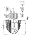
- a main magnetic field control 10 controls superconducting or resistive magnets 12 such that a substantially uniform, temporally constant main magnetic field is created along a z axis through an examination region 14.
- a couch (not illustrated) supports a subject to be examined within the examination region 14 .
- a magnetic resonance echo means applies a series of radio frequencies (RF) and magnetic field gradient pulses to invert or excite magnetic spins, induce magnetic resonance, refocus magnetic resonance, manipulate magnetic resonance, spatially and otherwise encode the magnetic resonance, to saturate spins, and the like to generate magnetic resonance imaging and spectrography sequences.
- RF radio frequencies
- gradient pulse amplifiers 20 apply current pulses to one of two gradient coil sets associated with a double-duty gradient coil assembly 22 to create magnetic field gradients along x, y, and z axes of the examination region 14 .
- the shielded gradient coil structure 22 consists of two sets of primary coils and a single set of shielding or screening coils which are used to screen the fringe field of each primary coil set either individually or combined.
- a digital radio frequency transmitter 24 transmits radio frequency pulses or pulse packets to a whole-body RF coil 26 to transmit RF pulses into the examination region.
- a typical radio frequency pulse is composed of a packet of immediately contiguous pulse segments of short duration which taken together with each other and any applied gradients achieve a selected magnetic resonance manipulation. For whole-body applications, the resonance signals are commonly picked up by the whole-body RF coil 26.
- specialized radio frequency coils are placed continuous to the selected region.
- an insertable RF coil may be inserted surrounding a selected region at the isocentre of the bore.
- the insertable RF coil is used to excite magnetic resonance and receive magnetic resonance signals emitting from the patient in the region being examined.
- the insertable RF coil can be used to only receive resonance signals introduced by whole-body coil RF transmissions.
- the resultant radio frequency signals are picked up by the whole-body RF coil 26, the insertable RF coil, or other specialized RF coils and demodulated by a receiver 30 , preferably a digital receiver.
- a sequence control circuit 40 controls the gradient pulse amplifiers 20 and the transmitter 24 to generate any of a plurality of multiple echo sequences such as echo planar imaging, echo volume imaging, gradient and spin echo imaging, fast spin echo imaging, and the like.
- the receiver 30 receives a plurality of data lines in rapid succession following each RF excitation pulse.
- the radio frequency signals received are demodulated and reconstructed into an image representation by a reconstruction processor 50 which applies a two dimensional Fourier transform or other appropriate reconstruction algorithm.
- the image may represent a planar slice through the patient, an array of parallel planar slices, a three dimensional volume, of the like.
- the image is then stored in an image memory 52 where it may be accessed by a display, such as a video monitor 54 which provides a human readable display of the resultant image.
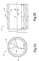
- the double-duty gradient coil structure 22 includes two independent sets of primary gradient coils 60, 62 and a single set of shielded (screening) coils 64 that screens the fringe field of each primary coil set, either individually or combined.
- the total length of the first primary coil set 60 is denoted as L a
- the length of the second primary coil set 62 is denoted as L a ' .
- the two lengths L a , L a can be equal, or different from each other.
- the length of the common shielding coil set 64 is assumed infinite for mathematical calculations, but in physical reality is truncated to L b .
- the radius of the first primary coil set is denoted as a
- the radius of the second primary coil set is denoted as a'
- the radius of the shielding coil set is denoted as b .
- the first, high-efficiency, independently-shielded, modular gradient coil set 60 (having a first set of primary gradient coils and the same set of shielding coils as a second set of primary coils) is intended for use with high-speed imaging applications, such as ultra fast MR sequencing, where high-field strength but lower field quality is acceptable over a significantly smaller imaging volume.
- the second, low-efficiency, independently-shielded, modular gradient coil set 62 (having a second primary gradient coil set and the same shielding coil set as the first primary coil set), is intended for use with conventional MR imaging applications, and exhibits relatively low field strengths with high field quality (uniformity and linearity) over an imaging volume suitable for entire body coverage, with inherently low dB/dt and eddy current levels.
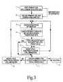
- step 3 the geometric configurations of the first primary coil with the common shield (step I ) and the second primary coil with the common shield (step 2) are chosen.
- step 3 the optimization process of each primary coil with the same common shield using an energy/inductance minimization algorithm is performed (step 3).
- step 4 the eddy current inside a prescribed imaging volume is evaluated for both primary coil configurations (step 4). If the eddy currents from either primary coils with the common shield meet the eddy current target value for this particular volume (step 5), then proceed by discretizing each primary and the shielding coil. The goal is that each primary coil and the common shield coil must have exact integer number of turns when they share the same current (step 7).
- step 8 the field characteristics and/or coil radius and/or length are modified (step 8) and proceed again from step 3. If the eddy currents from the step 5 do not meet the target residual eddy current inside the imaging volume, the field characteristics and/or coil radius and/or length are modified (step 6) and proceed again from step 3. This cycle continues until an acceptable solution (step 9) is found that satisfies the target criteria.
- step 3 The theoretical development of the energy optimization algorithm (step 3) will be discussed for both the transverse and the axial gradient coil. The presentation will be done for only one primary and screening coil structure since, the algorithm for optimizing the second primary and shielding coil structure is identical to the previous algorithm.
- the design of a finite, shielded transverse (x) gradient coil involves the design of the primary coil (the coil that generates the gradient field) based on the inverse approach methodology.
- the gradient magnetic field must be antisymmetric in the x direction around the geometric centre of this coil, while it is symmetric along the y and z directions.
- the analytical expression of the current for the primary coil can be written as: where ⁇ ( ⁇ -a) is the restriction that the current is confined on the cylindrical surface with radius a .
- the functional ⁇ is constructed in terms of W and B z as: where ⁇ j are the Lagrange multipliers and B zSC . represent the constraint values of the z component of the magnetic field at the specified N points.
- ⁇ j are the Lagrange multipliers and B zSC . represent the constraint values of the z component of the magnetic field at the specified N points.
- E a quadratic function of the current, with respect to the current coefficients j a ⁇ n
- a matrix equation results which j a ⁇ n ' must satisfy: where the evaluation of the Lagrange multipliers can be done via the constraint equation.
- the radius of the cylinder for the first primary coil is equal to 0.365620 m and its total length is restricted to 1.046800 m.
- the radius of the cylinder is equal to 0.361175 m with a total length equal to 1.015500 m.
- the radius of the secondary coil is equal to 0.443485 m.
- the constraints for the design of the first primary coil are shown in Table 1.
- the constraints for the second primary coil with the single shield are shown in Table 2.
- the first constraint point defines a gradient strength for the first primary and single shield coil to be 20.0 mT/m
- the second constraint point specifies a -5% linearity of the gradient field along the gradient (x) axis and up to the distance of 25.5 cm for the isocentre of the gradient field
- the third constraint point specifies a -20% uniformity of the gradient field inside the 45 cm imaging volume.
- values for B zsc (2n) are in T. n ⁇ i z i B zsc (2n) 1 0.001 0 0.0000258 2 0.245 0 0.005819332 3 0.001 0.2 0.0000178
- the first constraint point defines a gradient strength for the second primary and single shield coil to be 25.8 mT/m
- the second constraint point specifies a -8% linearity of the gradient field along the gradient (x) axis and up to the distance of 24.5 cm for the isocentre of the gradient field
- the third constraint point specifies a -31% uniformity of the gradient field inside the 45 cm imaging volume.
- the values for the Fourier coefficients for the current density of the first, the second primary and the single shield coil are generated.
- the Stream Function technique Applying the Stream Function technique to the continuous current densities for both the primary coils and the shielding coil, the discrete current patterns for these coils were generated.
- the first primary and shield configuration the Stream Function technique generates 22 discrete loops on the primary coil, and 12 loops on the single shield.
- the common current per loop is 328.19 amps.
- the eddy current from the discrete coil configuration is 0.182% over a 45 cm DSV.
- the design of the finite shielded transverse z-gradient (axial) coil involves the design of the primary coil (the coil that generates the gradient field) based on the inverse approach methodology.
- the gradient magnetic field must be antisymmetric in the z direction around the geometric centre of this coil, while it is symmetric along the x and y directions.
- the radius of the cylinder for the first primary coil is equal to 0.358500 m and its total length is restricted to 1.0440 m.
- the radius of the cylinder is equal to 0.36225 m with a total length equal to 1.0660 m.
- the radius of the common secondary coil is equal to 0.433225 m.
- the constraints are shown in Table 4.
- the constraints are shown in Table 5.
- the first constraint point defines a gradient strength for the first primary and common shield coil to be 20.0 mT/m
- the second constraint point specifies a -5% linearity of the gradient field along the gradient ( z ) axis and up to the distance of 22.5 cm for the isocentre of the gradient field, while the rest of the constraint points specify the uniformity of the gradient field inside the 45 cm imaging volume.
- Constraint set used for the design for the second primary gradient coil and common shield structure Values for ⁇ and z are in m, values for B zSC (2n) are in T. n ⁇ i z i B zSC (2n) 1 0 0.001 0.00003 2 0 0.225 0.00617524 3 0.1625 0.001 0.0000313 4 0.225 0.001 0.00029879
- the first constraint point defines a gradient strength for the second primary and common shield coil to be 30.0 mT/m
- the second constraint point specifies a -5% linearity of the gradient field along the gradient z axis and up to the distance of 22.5 cm for the isocentre of the gradient field, while the rest of the constraint points specify the uniformity of the gradient field inside the 45 cm imaging volume.
- the values for the Fourier coefficients for the current density of the first, the second primary, and the single shield coil are generated.
- the centre of mass technique Applying the centre of mass technique to the continuous current densities for both the primary coils and the shielding coil, the discrete current patterns for these coils were generated.
- the centre of mass technique generates 52 discrete loops on the primary coil, and 34 loops on the single shield.
- the common current per loop is 318.88 amps.
- the eddy current from the discrete coil configuration is 0.329% over a 45 cm DSV.
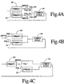
- Figures 4A, 4B, and 4C show alternate ways of electrically connecting the two primary coil sets 60, 62 with the single shield coil set 64.
- alternative methods include the in-series or in-parallel connections of the two primaries with the single shield, or independent connections between the two primaries and the single shield. It is also contemplated that the primary and shielding coils can be interleaved or stacked depending on radius requirements.
- the double-duty gradient coil assembly of the present invention utilizes only one shield coil set to control the fringe field of two independent primary coil sets over a prescribed imaging volume(s).
- the first primary coil-single shield configuration is a high-efficiency configuration with low quality field
- the second primary coil-single shield configuration is a conventional efficiency configuration with moderate gradient strength and high quality field.
- the single shield two primary coil configuration can be adjusted such that each primary single shield coil configuration can generate the desired field qualities inside a common imaging volume.
- the configuration of two primary coil sets with a single common shield set helps on the reduction of the cost of manufacturing, since the second shield coil set is not necessary.
- the construction of a dual duty gradient set can be more simple and compact.
- the single shield two primary coil configuration can be adjusted such that each primary single shield coil configuration can generate the desired field qualities in such a way that both coils have the same length.
- the specified current patterns can be changed to produce either better linearity at the price of coil efficiency, and/or greater efficiency at the price of linearity.
- the dimensions (radius and/or length) of the cylindrical gradient coils can be changed to be increased or decreased according to the preferred application.
- the lengths of the two primary coils can be similar or different.
- the perspective imaging volumes that the two primary coils with the single shield generate can be the same or different.
- each primary coil can be etched on each side of a dielectric backing.
- Each primary coil can be etched on a separate backing and can be placed on the inside or outside surface of the gradient tube structure.
- a single or double former can be used to mount the two primary coil sets and the secondary gradient structure.
- the present invention can be applied to other alternative gradient coil geometries, such as elliptical, planar, flared, etc., as well as the asymmetric gradient coil designs or any combination thereof.
- the present invention can be also applied to the design of gradient coil structures suitable for vertically (or transversely) oriented main magnetic fields.
- the disclosed primary and screen coil sets can be bunched (concentrated) or thumbprint designs generated using forward or inverse approach methods.
- the two primary and the shield coils can have any possible mixing of bunched and/or thumbprint designs.
- zero net thrust force or torque can be incorporated into the proposed design algorithm in a known manner.
- more than two primary coils and more than one screening coil can also be designed by employing the above process, as long as the total number of the screening coils is less than the total number of the primary coils, and the number of screening coils is not zero.
- the first primary coil with the common shield set can be optimized simultaneously or separate from the second primary coil with the common shield set.
- the illustrated double-duty gradient coil assembly having two primary gradient coil sets and a common screening coil set have a number of advantages.
- One advantage is the provision of a single shielded gradient coil set to screen two independent primary gradient coil sets.
- Another advantage is the provision of a double-duty shielded gradient coil assembly that utilizes a single shield coil to screen two electrically and/or mechanically different primary coils.
- Another advantage is the provision of a double-duty shielded gradient coil assembly that utilizes a lesser number of shielding coil sets to screen a larger number of primary coil sets.
- Another advantage is the provision of a method for designing a double-duty, single shield-two primary coil gradient set using the inverse approach method and eddy current optimization.
- Another advantage is the provision of a shielded, double-duty gradient coil assembly having improved gradient strength and rise time over existing gradient coil structures.
Landscapes
- Physics & Mathematics (AREA)
- Health & Medical Sciences (AREA)
- Epidemiology (AREA)
- Condensed Matter Physics & Semiconductors (AREA)
- General Physics & Mathematics (AREA)
- Magnetic Resonance Imaging Apparatus (AREA)
Applications Claiming Priority (2)
| Application Number | Priority Date | Filing Date | Title |
|---|---|---|---|
| US200659 | 1980-10-27 | ||
| US09/200,659 US6049207A (en) | 1998-11-25 | 1998-11-25 | Double-duty gradient coil assembly having two primary gradient coil sets and a common screening coil set |
Publications (2)
| Publication Number | Publication Date |
|---|---|
| EP1004890A2 true EP1004890A2 (fr) | 2000-05-31 |
| EP1004890A3 EP1004890A3 (fr) | 2003-01-22 |
Family
ID=22742628
Family Applications (1)
| Application Number | Title | Priority Date | Filing Date |
|---|---|---|---|
| EP99308959A Withdrawn EP1004890A3 (fr) | 1998-11-25 | 1999-11-10 | Assemblage de bobines à gradient blindées pour l'imagerie par résonance magnétique |
Country Status (3)
| Country | Link |
|---|---|
| US (1) | US6049207A (fr) |
| EP (1) | EP1004890A3 (fr) |
| JP (1) | JP2000157515A (fr) |
Cited By (1)
| Publication number | Priority date | Publication date | Assignee | Title |
|---|---|---|---|---|
| WO2002042789A3 (fr) * | 2000-11-22 | 2002-10-17 | Marconi Medical Sys Inc | Correction de la distorsion du gradient multi-axe en temps reel faisant appel a un ensemble de shimes interactives |
Families Citing this family (20)
| Publication number | Priority date | Publication date | Assignee | Title |
|---|---|---|---|---|
| EP1046053A1 (fr) * | 1998-10-28 | 2000-10-25 | Koninklijke Philips Electronics N.V. | Dispositif d'imagerie par resonance magnetique, dote d'un blindage contre les courants d'eddy, integre mecaniquement dans le systeme de gradient |
| DE10109543B4 (de) * | 2001-02-28 | 2006-03-30 | Siemens Ag | Verfahren zum Betrieb eines Gradientenspulensystems eines Magnetresonanzgeräts |
| US6538443B2 (en) | 2001-03-20 | 2003-03-25 | Koninklijke Philips Electronics N.V. | MRI gradient coil with variable field of view and apparatus and methods employing the same |
| DE10120284C1 (de) * | 2001-04-25 | 2003-01-02 | Siemens Ag | Gradientenspulensystem und Magnetresonanzgerät mit dem Gradientenspulensystem |
| US6479999B1 (en) | 2001-06-05 | 2002-11-12 | Koninklijke Philips Electronics N.V. | Efficiently shielded MRI gradient coil with discretely or continuously variable field of view |
| WO2003080043A1 (fr) * | 2002-03-18 | 2003-10-02 | Immugen Pharmaceuticals, Inc. | Preparations topiques de resorcinols et de cannabinoides et leurs procedes d'utilisation |
| AU2003272029A1 (en) * | 2002-11-20 | 2004-06-15 | Koninklijke Philips Electronics N.V. | Self-shielded gradient field coil for magnetic resonance imaging |
| US7378849B2 (en) * | 2003-10-07 | 2008-05-27 | Sra International, Inc. | Method and apparatus for obtaining spatial information and measuring the dielectric constant of an object |
| WO2005112792A2 (fr) | 2004-05-14 | 2005-12-01 | Evalve, Inc. | Mecanismes de verrouillage pour dispositifs de fixation et methodes de fixation de ces dispositifs a un tissu |
| JP2006149722A (ja) | 2004-11-30 | 2006-06-15 | Ge Medical Systems Global Technology Co Llc | マグネットシステムおよびmri装置 |
| US7382133B1 (en) * | 2005-04-29 | 2008-06-03 | Fonar Corporation | Self-shielded gradients and method of designing and producing self-shielded gradients |
| US7932722B2 (en) * | 2009-04-27 | 2011-04-26 | General Electric Company | Transversely folded gradient coil |
| CN105445683B (zh) * | 2015-11-16 | 2018-05-11 | 河海大学 | 一种柱面横向自屏蔽梯度线圈设计方法 |
| CN108107390A (zh) * | 2017-12-29 | 2018-06-01 | 鑫高益医疗设备股份有限公司 | 一种超导磁体外磁屏蔽线圈的优化设计方法 |
| CN110456293B (zh) * | 2019-07-22 | 2021-07-20 | 惠仁望都医疗设备科技有限公司 | 一种自屏蔽梯度线圈的设计方法 |
| CN112858972A (zh) * | 2019-11-28 | 2021-05-28 | 西门子(深圳)磁共振有限公司 | 梯度线圈及磁共振成像系统 |
| GB202106961D0 (en) * | 2021-05-14 | 2021-06-30 | Magnetic Shields Ltd | A magnetic shield |
| US12601801B2 (en) | 2021-05-14 | 2026-04-14 | Magnetic Shields Limited | Magnetic shield |
| CN114264993A (zh) * | 2021-12-04 | 2022-04-01 | 河北惠仁医疗设备科技有限公司 | 一种锥面自屏蔽梯度线圈的设计方法 |
| EP4300123B1 (fr) * | 2022-06-29 | 2025-10-29 | Siemens Healthcare Limited | Scanner à résonance magnétique doté d'une bobine de gradient blindée passivement |
Family Cites Families (8)
| Publication number | Priority date | Publication date | Assignee | Title |
|---|---|---|---|---|
| EP0365065B1 (fr) * | 1985-09-20 | 2003-03-12 | Btg International Limited | Ecran de champs magnétiques |
| US4794338A (en) * | 1987-11-25 | 1988-12-27 | General Electric Company | Balanced self-shielded gradient coils |
| US5296810A (en) * | 1992-03-27 | 1994-03-22 | Picker International, Inc. | MRI self-shielded gradient coils |
| JPH03182232A (ja) * | 1989-12-11 | 1991-08-08 | Toshiba Corp | 磁気共鳴イメージング装置 |
| US5311135A (en) * | 1992-12-11 | 1994-05-10 | General Electric Company | Multiple tap gradient field coil for magnetic resonance imaging |
| JPH0884716A (ja) * | 1994-09-16 | 1996-04-02 | Toshiba Corp | 勾配磁場コイル |
| GB2295020B (en) * | 1994-11-03 | 1999-05-19 | Elscint Ltd | Modular whole - body gradient coil |
| US5561371A (en) * | 1995-09-27 | 1996-10-01 | General Electric Company | Transverse gradient coil |
-
1998
- 1998-11-25 US US09/200,659 patent/US6049207A/en not_active Expired - Fee Related
-
1999
- 1999-11-10 EP EP99308959A patent/EP1004890A3/fr not_active Withdrawn
- 1999-11-25 JP JP11335111A patent/JP2000157515A/ja active Pending
Cited By (1)
| Publication number | Priority date | Publication date | Assignee | Title |
|---|---|---|---|---|
| WO2002042789A3 (fr) * | 2000-11-22 | 2002-10-17 | Marconi Medical Sys Inc | Correction de la distorsion du gradient multi-axe en temps reel faisant appel a un ensemble de shimes interactives |
Also Published As
| Publication number | Publication date |
|---|---|
| EP1004890A3 (fr) | 2003-01-22 |
| JP2000157515A (ja) | 2000-06-13 |
| US6049207A (en) | 2000-04-11 |
Similar Documents
| Publication | Publication Date | Title |
|---|---|---|
| EP1004890A2 (fr) | Assemblage de bobines à gradient blindées pour l'imagerie par résonance magnétique | |
| US5036282A (en) | Biplanar gradient coil for magnetic resonance imaging systems | |
| US4733189A (en) | Magnetic resonance imaging systems | |
| US6538443B2 (en) | MRI gradient coil with variable field of view and apparatus and methods employing the same | |
| US5311135A (en) | Multiple tap gradient field coil for magnetic resonance imaging | |
| EP0562707B1 (fr) | Appareil et méthodes de résonance magnétiques | |
| US6078177A (en) | Flared gradient coil set with a finite shield current | |
| US6262576B1 (en) | Phased array planar gradient coil set for MRI systems | |
| EP2030036A2 (fr) | Bobines à gradient transversal asymétrique tridimensionnel | |
| JP2006506155A (ja) | 磁気共鳴撮像用の自己遮蔽傾斜磁場コイル | |
| US6342787B1 (en) | Real-time multi-axis gradient distortion correction using an interactive shim set | |
| US5177441A (en) | Elliptical cross section gradient oil | |
| EP0701143B1 (fr) | Appareil d'imagerie par résonance magnétique | |
| EP0913699B1 (fr) | Système plat de bobines à gradient pour l'imagerie par résonance magnétique disposé d'un seul côté de l'objet à examiner | |
| US6100692A (en) | Gradient coil set with a finite shield current | |
| US5942898A (en) | Thrust balanced bi-planar gradient set for MRI scanners | |
| EP0690312B1 (fr) | Bobines à gradient asymétriques pour l'imagerie par résonance magnétique | |
| US6278276B1 (en) | Phased array gradient coil set with an off center gradient field sweet spot | |
| US6236203B1 (en) | Super shielding of finite length structures in open magnetic and electric systems | |
| EP1094330B1 (fr) | Appareil d'imagerie à résonance magnétique et procédé de conception d'un dispositif de bobines à gradient | |
| EP0690313A1 (fr) | Appareil d'imagerie par résonance magnétique approprié pour obtenir l'image du poignet | |
| WO1999054747A1 (fr) | Projection de champ de gradient magnetique | |
| EP1457788A2 (fr) | Aimant de lecture pulsé pour l'IRM |
Legal Events
| Date | Code | Title | Description |
|---|---|---|---|
| PUAI | Public reference made under article 153(3) epc to a published international application that has entered the european phase |
Free format text: ORIGINAL CODE: 0009012 |
|
| AK | Designated contracting states |
Kind code of ref document: A2 Designated state(s): AT BE CH CY DE DK ES FI FR GB GR IE IT LI LU MC NL PT SE |
|
| AX | Request for extension of the european patent |
Free format text: AL;LT;LV;MK;RO;SI |
|
| RAP1 | Party data changed (applicant data changed or rights of an application transferred) |
Owner name: MARCONI MEDICAL SYSTEMS, INC. |
|
| PUAL | Search report despatched |
Free format text: ORIGINAL CODE: 0009013 |
|
| AK | Designated contracting states |
Kind code of ref document: A3 Designated state(s): AT BE CH CY DE DK ES FI FR GB GR IE IT LI LU MC NL PT SE |
|
| AX | Request for extension of the european patent |
Free format text: AL;LT;LV;MK;RO;SI |
|
| AKX | Designation fees paid | ||
| REG | Reference to a national code |
Ref country code: DE Ref legal event code: 8566 |
|
| STAA | Information on the status of an ep patent application or granted ep patent |
Free format text: STATUS: THE APPLICATION IS DEEMED TO BE WITHDRAWN |
|
| 18D | Application deemed to be withdrawn |
Effective date: 20030723 |