EP1004995A1 - Warenlager mit einfacher Wiederanfüllungsmöglichkeit - Google Patents
Warenlager mit einfacher Wiederanfüllungsmöglichkeit Download PDFInfo
- Publication number
- EP1004995A1 EP1004995A1 EP99309375A EP99309375A EP1004995A1 EP 1004995 A1 EP1004995 A1 EP 1004995A1 EP 99309375 A EP99309375 A EP 99309375A EP 99309375 A EP99309375 A EP 99309375A EP 1004995 A1 EP1004995 A1 EP 1004995A1
- Authority
- EP
- European Patent Office
- Prior art keywords
- shelf
- storage apparatus
- commodity storage
- end portion
- rear end
- Prior art date
- Legal status (The legal status is an assumption and is not a legal conclusion. Google has not performed a legal analysis and makes no representation as to the accuracy of the status listed.)
- Withdrawn
Links
Images


Classifications
-
- A—HUMAN NECESSITIES
- A47—FURNITURE; DOMESTIC ARTICLES OR APPLIANCES; COFFEE MILLS; SPICE MILLS; SUCTION CLEANERS IN GENERAL
- A47F—SPECIAL FURNITURE, FITTINGS, OR ACCESSORIES FOR SHOPS, STOREHOUSES, BARS, RESTAURANTS OR THE LIKE; PAYING COUNTERS
- A47F5/00—Show stands, hangers, or shelves characterised by their constructional features
- A47F5/0081—Show stands or display racks with movable parts
- A47F5/0093—Show stands or display racks with movable parts movable in a substantially horizontal direction
-
- G—PHYSICS
- G07—CHECKING-DEVICES
- G07F—COIN-FREED OR LIKE APPARATUS
- G07F11/00—Coin-freed apparatus for dispensing, or the like, discrete articles
- G07F11/02—Coin-freed apparatus for dispensing, or the like, discrete articles from non-movable magazines
- G07F11/28—Coin-freed apparatus for dispensing, or the like, discrete articles from non-movable magazines in which the magazines are inclined
-
- G—PHYSICS
- G07—CHECKING-DEVICES
- G07F—COIN-FREED OR LIKE APPARATUS
- G07F11/00—Coin-freed apparatus for dispensing, or the like, discrete articles
- G07F11/02—Coin-freed apparatus for dispensing, or the like, discrete articles from non-movable magazines
- G07F11/38—Coin-freed apparatus for dispensing, or the like, discrete articles from non-movable magazines in which the magazines are horizontal
Definitions
- the present invention relates to a commodity storage apparatus suitable for a vending machine which permits to drop forwardly, for example, predetermined packaged commodities for carrying out or delivery of the packaged commodities.
- a conventional commodity storage apparatus is shown in Japanese Patent Publication (Unexamined) No. 9-106,476.
- the conventional commodity storage apparatus comprises an apparatus frame, a plurality of shelves arranged in a vertical direction to space with each other and fixed to the apparatus frame, and a plurality of delivery mechanisms placed at forward ends of the shelves, respectively.
- Each shelf has a forwardly slant portion and houses commodities therein. Responsive to a vending signal known in the art, each delivery mechanisms makes each of the commodities be slid down forwardly one by one from each shelf. The commodities are supplied from a front face of the commodity storage apparatus to the shelves, respectively.
- a commodity storage apparatus for storing commodities, comprising an apparatus frame fixedly installed, a shelf supported by the apparatus frame for housing the commodities, the shelf being movable between a forward position and a backward position, and attitude control means connected to the apparatus frame and the shelf and responsive to movement of the shelf between the forward and the backward positions for controlling an attitude of the shelf in a predetermined plane extending in a fore and aft direction and a vertical direction.
- a commodity storage apparatus comprising a shelf for housing commodities in a back and forth alignment relation, an apparatus frame supporting the shelf in a forwardly inclined relation, the shelf being drawable in a forward direction of the apparatus frame, and attitude control means connected to the shelf and the apparatus frame and responsive to movement of the shelf in the forward direction for controlling an attitude of the shelf in such a manner that a rear end of the shelf is descended when the shelf is moved in a forward direction and that the rear end of the shelves is ascended when the shelf is moved in a backward direction.
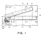
- Fig. 1 is a schematic side view of a part of a commodity storage apparatus for a vending machine according to a first embodiment of the invention.
- the commodity storage apparatus is used for a vending machine known in the art and comprises a pair of side plates (only one of which is illustrated) 11 which are opposite to space together in a left and right direction.
- Each of the side plates 11 extends parallel to a predetermined plane defined by a fore and aft direction and a vertical direction.
- a combination of the side plates 11 is referred to as an apparatus frame.
- the commodity storage apparatus further comprises a commodity shelf 12 for receiving commodities and a movable member or a slide member 13 supported by the side plates 11 to be movable in the fore and aft direction.
- the commodity shelf 12 is supported by the side plates 11 and the slide member 13 to have an attitude or posture controlled in the predetermined plane in the manner which will later be described.
- Each side plate 11 has a first guide groove 14 for supporting the slide member 13 and a second guide groove 15 for supporting the commodity shelves.
- the first guide groove 14 is formed in a linear configuration and extends in the fore and aft direction.
- a roller 16 is rotatably attached under the first groove 14.
- the second guide groove 15 which is formed in a linear configuration and has a first part extending in a fore and aft direction and a second part downwardly inclined in the front direction. It is to be noted that the second part of the second guide groove 15 extends in an oblique direction intersecting the fore and aft direction and the vertical direction.
- flanged rollers (only one of which is illustrated) 19 are rotatably attached as a guided member.
- Each roller 19 is rotatably engaged with the second guide groove 15 of the side plate 11.
- a delivery or carrying out mechanism is provided to the front end of the commodity shelf 12 for carrying out the commodities to the front portion of the apparatus.
- a combination of the second guide groove 15 and the roller 19 will be referred to as a rear guiding arrangement.
- the slide member 13 is formed slightly wider than the width of the commodity shelf 12 and positioned at a lower portion of the commodity shelf 12.
- the slide member 13 is fixed on its both side surfaces with guide projections (only one of which is illustrated) 21 extending in the fore and aft direction and with rollers 22 (only one of which is illustrated) rotatably attached to the rear end portion of the guide projections 21.
- Each roller 22 is engaged with the first guide groove 14 of the side plate 11.
- the roller 22 is supported on a guide rail 23 formed by the first guide groove 14 and is rotated on the guide rail 23.
- Each guide projection 21 is supported by the roller 16 attached to the side plate 11.
- the slide member 13 is fixed on its both sides of the front end portion with pins (only one of which is illustrated) 24 for supporting the front end portion of the commodity shelf 12.
- the shelf 12 is fixed on its both sides of the front end portion with coupling plate (only one of which is illustrated) 25 each having a groove 26 opened downwardly.
- Each pin 24 is pivotally engaged with the groove 26 of each coupling plate 25. Therefore, the shelf 12 is rotatably supported around the pins 24.
- a combination of the pins 24 and the coupling plates 25 will be referred to as a pivotal support arrangement.
- a combination of the slide member 13 and the pivotal support arrangement will be referred to as a front guiding arrangement.
- a combination of the front and the rear guiding arrangements is referred to as an attitude control arrangement.
- the commodity storage apparatus further comprises a stopper 31 placed under the slide member 13 for stopping the commodity shelf 12 at the backward position.
- the stopper 31 comprises an engaging plate 32, a fixing plate 33, a handle 35, and a lever 36.
- the stopper 31 extends between the side plates 11 in the left and right direction and is fixed to the side plates 11.
- the fixing plate 33 is fixed to a lower surface of the slide member 13.
- the handle 35 is pivotally attached to the fixing plate 33 through a first shaft 37.
- the lever 36 is pivotally attached to the fixing plate 33 through a second shaft 38 and extends between the handle 35 and the engaging plate 32.
- each roller 19 is positioned at a rear end of the second guide groove 15, that is, at the inclined portion of the second guide groove 15. Therefore, the shelf 12 is held in a forwardly inclined posture or attitude at a backward position. Then, when the slide member 13 is pulled or drawn forwardly to be placed at a backward position as shown in Fig. 3B, the slide member 13 is moved forward together with the commodity shelf 12. In this event, each roller 19 is moved along the inclined portion of the second guide groove 15 toward the front end. Thus, the rear end portion of the shelf 12 is lowered or descended until each roller 19 arrives at the front end portion of the second guide groove 15, where the shelf 12 is placed in a horizontal state as shown in Fig. 3C.
- the commodity shelf 12 is forwardly movably supported by the slide member 13 which is slidable in the fore and aft direction.
- the slide member 13 when the slide member 13 is moved in the forward direction, the rear end portion of the commodity shelf 12 is descended to be placed at a relatively lower position.
- the rear end of the shelf 12 is ascended to be placed at a relatively higher position . Therefore, when the slide member 13 is drawn or pulled in the forward direction for the purpose of supplementing the commodities, the commodity shelf 12 is held in a horizontal posture or attitude. This will permit an extremely easy supplement of the commodities.
- the carrying-out mechanism 40 has a pair of take-out members 41 and 42 which are depressibly disposed, in a back and forth alignment (front and back rows) relation, on the bottom surface of the commodity shelf 12, and driving portion 43 for selectively depressing the take-out members 41 and 42.
- Each of the take-out members 41 and 42 serves to engage or hold commodities 44 placed on the shelf 12.
- Fig. 4A In this state, the commodity 44 of the front row is engaged with and held by the take-out member 41.
- the take-out member 41 of the front row is depressed, as shown in Fig. 4B.
- the take-out member 42 of the back row is projected on the shelf 12.
- FIGs. 5 and 6 the description will be made as regards a commodity storage apparatus according to a second embodiment of the invention.
- the same reference numerals are used for representing the same or similar parts and elements in the previous embodiment shown in Figs. 1 to 4.
- the commodity storage apparatus of Figs. 5 and 6 comprises a plurality of guide grooves 14 and 15 for each of the side plates 11, a plurality of commodity shelves 12, and a plurality of slide members 13.
- the slide members 13 are arranged in the vertical direction to be spaced with one another.
- the commodity shelves 12 are placed over the slide members 13, respectively.
- Each of the slide members 13 has a bottom surface on the front end portion only and an insertion portion 45 on the rear end portion so that the rear end of the other shelf 12 of the lower position can be inserted into the insertion portion 45.
- the commodity shelves 12 are arranged in an up and down configuration in such a manner that the rear end portions of the shelves of lower positions can be inserted into, or received by, the insertion portions 45 of the slide members 13, as illustrated in Fig. 5. This permits to make the space between the adjacent shelves 12 to be narrower so that the entire size of the apparatus can be made smaller in a vertical direction.
- the present invention has thus far been described in connection with a few embodiments thereof, it will readily be possible for those skilled in the art to put this invention into practice in various other manners.
- the present invention is applicable to a commodity storage apparatus in which commodities are housed in the shelf to have a modified relation different from the fore and aft alignment relation.
Landscapes
- Physics & Mathematics (AREA)
- General Physics & Mathematics (AREA)
- Vending Machines For Individual Products (AREA)
- Control Of Vending Devices And Auxiliary Devices For Vending Devices (AREA)
Applications Claiming Priority (2)
| Application Number | Priority Date | Filing Date | Title |
|---|---|---|---|
| JP33227598 | 1998-11-24 | ||
| JP10332275A JP2000155869A (ja) | 1998-11-24 | 1998-11-24 | 商品収納装置 |
Publications (1)
| Publication Number | Publication Date |
|---|---|
| EP1004995A1 true EP1004995A1 (de) | 2000-05-31 |
Family
ID=18253132
Family Applications (1)
| Application Number | Title | Priority Date | Filing Date |
|---|---|---|---|
| EP99309375A Withdrawn EP1004995A1 (de) | 1998-11-24 | 1999-11-24 | Warenlager mit einfacher Wiederanfüllungsmöglichkeit |
Country Status (3)
| Country | Link |
|---|---|
| US (1) | US6199965B1 (de) |
| EP (1) | EP1004995A1 (de) |
| JP (1) | JP2000155869A (de) |
Cited By (2)
| Publication number | Priority date | Publication date | Assignee | Title |
|---|---|---|---|---|
| FR2820412A1 (fr) * | 2001-02-07 | 2002-08-09 | Patrick Dauchy | Armoire de rangement de reserve automatique |
| FR2861062A1 (fr) * | 2003-10-17 | 2005-04-22 | Stock 3P | Perfectionnement aux installations de stockage de charges, en particulier de produits conditionnes en palettes ou similaires |
Families Citing this family (10)
| Publication number | Priority date | Publication date | Assignee | Title |
|---|---|---|---|---|
| US6820979B1 (en) * | 1999-04-23 | 2004-11-23 | Neuroptics, Inc. | Pupilometer with pupil irregularity detection, pupil tracking, and pupil response detection capability, glaucoma screening capability, intracranial pressure detection capability, and ocular aberration measurement capability |
| US7584843B2 (en) * | 2005-07-18 | 2009-09-08 | Philip Morris Usa Inc. | Pocket-size hand-held container for consumer items |
| DE102007030330B4 (de) * | 2007-06-29 | 2010-07-22 | Airbus Deutschland Gmbh | Schwenkbarer Geräteträger in Kombination mit modifizierter Gepäckablage |
| DE102008006741B4 (de) * | 2008-01-30 | 2014-04-10 | Airbus Operations Gmbh | Lösbares Befestigen einer Komponente in einem Flugzeug |
| US9737139B1 (en) * | 2010-11-23 | 2017-08-22 | Drawers In Motion, LLC | Rack and drawer systems |
| US9833072B1 (en) * | 2010-11-23 | 2017-12-05 | Drawers In Motion, LLC | Rack and drawer systems and devices |
| US10376057B2 (en) | 2010-11-23 | 2019-08-13 | Drawers In Motion, LLC | Rack and drawer systems |
| US10314412B2 (en) * | 2015-09-10 | 2019-06-11 | Retail Space Solutions Llc | Retractable hinged shelf display |
| JP2018175535A (ja) * | 2017-04-17 | 2018-11-15 | 中野冷機株式会社 | ショーケース |
| JP6882841B1 (ja) * | 2020-08-31 | 2021-06-02 | 中野冷機株式会社 | ショーケース |
Citations (4)
| Publication number | Priority date | Publication date | Assignee | Title |
|---|---|---|---|---|
| DE2402376A1 (de) * | 1974-01-18 | 1975-07-24 | Heinrich Walter | Schubladenschrank |
| US4809855A (en) * | 1987-06-24 | 1989-03-07 | Legettt & Platt, Incorporated | Display rack |
| GB2286576A (en) * | 1994-02-16 | 1995-08-23 | Nigel Stuart Murray Simmons | An automatically adjusting support device for a container |
| JPH09106476A (ja) | 1995-10-11 | 1997-04-22 | Silk Hosei Kojo:Kk | 自動販売装置 |
Family Cites Families (5)
| Publication number | Priority date | Publication date | Assignee | Title |
|---|---|---|---|---|
| US1189371A (en) * | 1914-05-20 | 1916-07-04 | Herbert H Lyons | Display-fixture. |
| US2769551A (en) * | 1953-01-26 | 1956-11-06 | Grand Union Company | Display and delivery stand |
| US4314734A (en) * | 1980-05-07 | 1982-02-09 | Sybron Corporation | Cabinet drawer support |
| US5306077A (en) * | 1991-10-04 | 1994-04-26 | Megaspace Pty Ltd. | Drawer unit for displaying and dispensing of merchandise |
| US5599079A (en) * | 1994-08-19 | 1997-02-04 | Ranno; Douglas | Product display stand, and method of storing and displaying products using the same |
-
1998
- 1998-11-24 JP JP10332275A patent/JP2000155869A/ja active Pending
-
1999
- 1999-11-23 US US09/443,289 patent/US6199965B1/en not_active Expired - Fee Related
- 1999-11-24 EP EP99309375A patent/EP1004995A1/de not_active Withdrawn
Patent Citations (4)
| Publication number | Priority date | Publication date | Assignee | Title |
|---|---|---|---|---|
| DE2402376A1 (de) * | 1974-01-18 | 1975-07-24 | Heinrich Walter | Schubladenschrank |
| US4809855A (en) * | 1987-06-24 | 1989-03-07 | Legettt & Platt, Incorporated | Display rack |
| GB2286576A (en) * | 1994-02-16 | 1995-08-23 | Nigel Stuart Murray Simmons | An automatically adjusting support device for a container |
| JPH09106476A (ja) | 1995-10-11 | 1997-04-22 | Silk Hosei Kojo:Kk | 自動販売装置 |
Cited By (3)
| Publication number | Priority date | Publication date | Assignee | Title |
|---|---|---|---|---|
| FR2820412A1 (fr) * | 2001-02-07 | 2002-08-09 | Patrick Dauchy | Armoire de rangement de reserve automatique |
| WO2002063579A1 (fr) * | 2001-02-07 | 2002-08-15 | Patrick Dauchy | Armoire de rangement de reserve automatique |
| FR2861062A1 (fr) * | 2003-10-17 | 2005-04-22 | Stock 3P | Perfectionnement aux installations de stockage de charges, en particulier de produits conditionnes en palettes ou similaires |
Also Published As
| Publication number | Publication date |
|---|---|
| US6199965B1 (en) | 2001-03-13 |
| JP2000155869A (ja) | 2000-06-06 |
Similar Documents
| Publication | Publication Date | Title |
|---|---|---|
| US6199965B1 (en) | Commodity storage apparatus permitting ready supplement of commodities | |
| US3809259A (en) | Handle engaging tote pan retractor | |
| EP0781084A2 (de) | Elektronische Anlage mit Luftstromkanälen zur Kühlung | |
| JPS62501946A (ja) | 加工物連続供給装置 | |
| CZ20012987A3 (cs) | Podloľka pro zboľí | |
| EP0774732B1 (de) | Vorrichtung zur Kartenverarbeitung | |
| JP4151809B2 (ja) | 商品陳列ユニット | |
| EP1337983B1 (de) | Automatische ausgabevorrichtung | |
| US4208023A (en) | Tape transport mechanism of movable frame type with lateral guides | |
| JPH11346879A (ja) | 商品陳列棚 | |
| US6116462A (en) | Vending machine in which an article storage space has a size adjusted and locked by a given one of articles | |
| JPH0581537A (ja) | 自動販売機 | |
| KR0144520B1 (ko) | 자동 판매기의 상품 반출 장치 | |
| GB2030123A (en) | Dispensing mechanism for vending machines and the like | |
| JP2913971B2 (ja) | カ−ド繰り出し装置 | |
| JP6283702B2 (ja) | 調剤装置 | |
| JP2008093177A (ja) | 調剤装置のシート頭出し機構 | |
| JP2577110Y2 (ja) | 自動販売機の商品搬出装置 | |
| JPH10247272A (ja) | 自動販売機 | |
| GB2210731A (en) | Cartridge receiving apparatus | |
| CN220501667U (zh) | 一种斜坡式发药机储药架 | |
| JP3471554B2 (ja) | 自動販売機の商品収納装置 | |
| US6168246B1 (en) | Article providing apparatus which has excellent loading capacity and enables reduction in its installation area | |
| JP2012040070A (ja) | 物品陳列装置 | |
| JP3511185B2 (ja) | 自動販売機の搬出口幅調整装置 |
Legal Events
| Date | Code | Title | Description |
|---|---|---|---|
| PUAI | Public reference made under article 153(3) epc to a published international application that has entered the european phase |
Free format text: ORIGINAL CODE: 0009012 |
|
| AK | Designated contracting states |
Kind code of ref document: A1 Designated state(s): AT BE CH CY DE DK ES FI FR GB GR IE IT LI LU MC NL PT SE |
|
| AX | Request for extension of the european patent |
Free format text: AL;LT;LV;MK;RO;SI |
|
| AKX | Designation fees paid | ||
| REG | Reference to a national code |
Ref country code: DE Ref legal event code: 8566 |
|
| STAA | Information on the status of an ep patent application or granted ep patent |
Free format text: STATUS: THE APPLICATION IS DEEMED TO BE WITHDRAWN |
|
| 18D | Application deemed to be withdrawn |
Effective date: 20001201 |