EP1005110A2 - Steckvebinder mit Verriegelungsglied - Google Patents
Steckvebinder mit Verriegelungsglied Download PDFInfo
- Publication number
- EP1005110A2 EP1005110A2 EP99123528A EP99123528A EP1005110A2 EP 1005110 A2 EP1005110 A2 EP 1005110A2 EP 99123528 A EP99123528 A EP 99123528A EP 99123528 A EP99123528 A EP 99123528A EP 1005110 A2 EP1005110 A2 EP 1005110A2
- Authority
- EP
- European Patent Office
- Prior art keywords
- terminal
- front holder
- holder
- locking arm
- insertion slot
- Prior art date
- Legal status (The legal status is an assumption and is not a legal conclusion. Google has not performed a legal analysis and makes no representation as to the accuracy of the status listed.)
- Granted
Links
Images




Classifications
-
- H—ELECTRICITY
- H01—ELECTRIC ELEMENTS
- H01R—ELECTRICALLY-CONDUCTIVE CONNECTIONS; STRUCTURAL ASSOCIATIONS OF A PLURALITY OF MUTUALLY-INSULATED ELECTRICAL CONNECTING ELEMENTS; COUPLING DEVICES; CURRENT COLLECTORS
- H01R13/00—Details of coupling devices of the kinds covered by groups H01R12/70 or H01R24/00 - H01R33/00
- H01R13/40—Securing contact members in or to a base or case; Insulating of contact members
- H01R13/42—Securing in a demountable manner
- H01R13/436—Securing a plurality of contact members by one locking piece or operation
- H01R13/4364—Insertion of locking piece from the front
- H01R13/4365—Insertion of locking piece from the front comprising a temporary and a final locking position
Definitions
- This invention relates to a connector for use in connecting wire harness and the like in motor vehicles and, more specifically, relates to a connector containing a front holder for fastening terminals.
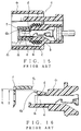
- Fig. 15 there is shown a longitudinal sectional view of a conventional connector containing a front holder.
- Fig. 16 there is shown a primary part of the longitudinal sectional view of the conventional connector for illustrating a problem encountered with the conventional connector.
- a body a 1 of a connector housing a there are provided a plurality of cylinders c each having a terminal receiving chamber b therein, a slit on an upper wall of an end portion c 1 of the cylinder c to form a cantilever-type resilient locking arm d, and a locking projection d 1 protruding toward the chamber b at a free end of the locking arm d.
- a terminal e to be inserted into the chamber b there is formed a locking hole e 1 into which the projection d 1 fits when the terminal e is fully inserted into the chamber b.
- the terminal e pushes the projection d 1 to deform the locking arm d, causing a detection end d 2 located at the end of the locking arm d protruding upward from the outer surface of the end portion c 1 of the cylinder c.
- the projection d 1 fits in the hole e 1 so that the locking arm d is lowered at the end portion c 1 of the cylinder c.
- a front holder f is inserted from the end of the body a 1 (from left in Fig. 15) and that along the outer surface of the end portion c 1 of the cylinder c.
- the front holder f cannot be inserted into an end of the inserted position caused by abutting against the detection end d 2 .
- the front holder f can be inserted into the end of the inserted position, namely to a final inserted position.
- the front holder f is half inserted into the cylinder c up to a provisional locking position where the front holder f does not contact with the detection end d 2 . Then, during the insertion of the terminal e into the chamber b, the locking arm d pushed by the terminal e is lifted from the cylinder c. When the terminal e is fully inserted, the locking arm d is lowered, then the front holder f can be inserted up to the end of the inserted position. Upon completion of the insertion, the front holder f is locked at the final inserted position by another locking projection (not shown in the figures).
- the front holder f has one function to detect the full insertion of the terminal e and another function to keep the terminal e from coming off, since the front holder f restrains the locking arm d from lifting when the front holder f is inserted to the final inserted position.
- the detection end d 2 of the resilient locking arm d which is lifted due to an incomplete insertion of the terminal e, must abut against a holder end f 1 , the end of the front holder f (see Fig. 16).
- the connector housing a and the front holder f are made of a synthetic resin and mold-shaped, there is some inevitable error in dimensions for these parts accompanied with the fabrication.
- lifted position g (see Fig. 16) of the detection end d 2 is influenced by various parameters such as the position and dimension of the terminal receiving chamber b, the diameter of the terminal e, and the dimension of the locking arm d and the projection d 1 thereof.
- internal diameter h of the front holder f has its own dimensional error accompanied with the above-mentioned fabrication.
- the inner diameter h must provide a clearance for allowing the front holder insertable with respect to the outer diameter of the end portion c 1 of the cylinder c (see Fig. 16).
- the lifted position g of the detection end d 2 can be lower than the position h corresponding to the lowest portion of the holder end f 1 , as illustrated in Fig. 16.
- the one situation is that the lifted position g becomes significantly low within the tolerance of the connector housing a and the terminal e.
- the another situation is that the position h becomes significantly high within the tolerance of the holder f.
- the front holder f can unfavorably be inserted to the final inserted position even if the locking arm d is in a lifted state, thereby causing a problem that the incomplete insertion of the terminal e cannot be detected.
- a first aspect of the present invention is to provide a connector composed in such a manner that it comprises a connector housing and a front holder, wherein the connector housing having: an insertion slot for receiving the front holder therein; a terminal receiving chamber for receiving the terminal therein; and a resilient locking arm which is resiliently deformed when pushed by the terminal and is resiliently recovered when the terminal is fully inserted into the terminal receiving chamber, the resilient locking arm having a detection end which is lowered toward the insertion slot when the resilient locking arm is resiliently deformed and is lifted toward the terminal receiving chamber when the resilient locking arm is recovered, and the front holder having: a holder end facing the detection end; and a stopper which stops the front holder at a provisional locking position where the holder end is apart from the detection end and is pushed into the insertion slot when the front holder passes through the provisional locking position, the front holder, the stopper of which is released, being shifted upward so that the holder end is movable in a direction to
- a second aspect of the present invention is the connector wherein the front holder has a resilient wall which slides on the insertion slot, and said stopper is provided on a sliding surface of the resilient wall.
- a third aspect of the present invention is the connector wherein a stopper face to abut on a stop end of the insertion slot is formed at the insertion side of the stopper. According to this structure, the front holder is securely locked at the provisional locking position.
- a fourth aspect of the present invention is the connector wherein the front holder has a resilient wall which slides on the insertion slot, said stopper being provided on a sliding surface of the resilient wall, and a stopper face to abut on a stop end of the insertion slot being formed at an insertion side of the stopper.
- the connector having the above structure can realize a secure locking of the terminal in the connector housing without overlooking the incomplete terminal insertion, even if there are some dimensional errors for the parts related accompanying by the fabrication thereof.
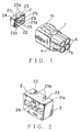
- FIG. 1 illustrates the first example of the present invention.
- Fig. 1 there are shown each perspective view of a female-type connector housing 1 and a front holder 2, in Fig. 2, a perspective view from the rear side of the front holder 2, and in Fig. 3 a longitudinal sectional view illustrating a state when a male-type terminal 3 and the front holder 2 are incompletely inserted into the connector housing 1.
- the connector housing 1 has a square tube body 1a at the forepart and a plurality of cylindrical pans, in which each terminal receiving chamber 5 is provided, at the rear. (In Fig. 1, there are shown two pairs of the terminal receiving chamber 5 provided up and down in the connector housing 1.)
- a male-type counter connector housing (not shown) is fitted and a front wall surface 7 against which an end surface of the counter connector housing abuts.
- an stop end 8 located on the left side of the wall surface 7 in Fig. 3 and insertion slots 9a and 9b, each has a pair of slots up and down, which extend from the stop end 8 toward the rear of the housing 1.
- insertion guide walls 10a and 10b are formed inside the insertion slots 9a and 9b, respectively, each of which extends from the bottom of the insertion slot toward the front of the housing 1.
- the upper terminal receiving chamber 5 in Fig. 3 there are formed a hole 11 which opens at the front wall surface 7 and a notch 12 which extends from the chamber 5 to the insertion slot 9a, and a cantilever-type resilient locking arm 13 extended from the notch 12 toward the front of the housing 1.
- the lower terminal receiving chamber 5 in Fig. 3 has the same structure with that of the upper one.
- a locking projection 14 is formed on the upper surface of the locking arm 13 and a detection end 15 is formed at the end of the locking arm 13.
- a tub-shaped electrically connecting portion 16 which protrudes through the hole 11 to fit in a counter terminal (not shown), and at the intermediate portion there is formed a locking hole 17 in which the locking projection 14 fits when the terminal 3 is fully inserted, and at the rear end there is formed a electrically connecting portion 19 which connects an electric wire 18.
- a seal 20 is also provided for the terminal 3 to seal an opening between the wire 18 and the terminal receiving chamber 5 thereby to ensure the waterproof (see Fig. 6).
- insertion walls 21a and 21b each of which protrudes frontward at the upper end and at the intermediate portion of the holder 2, respectively, and there is formed a lower wall 22 at the lower end of the holder 2.
- the insertion wall 21a at the upper end is inserted into the insertion slot 9a to slide on the upper surface of the insertion guide wall 10a.
- the insertion wall 21b at the intermediate portion is inserted into the insertion slot 9b to slide on the upper surface of the insertion guide wall 10b.
- notch 23 Two hollow portions of notch 23 are formed at the end surface of the insertion walls 21a and 21b.
- the bottom surface of each hollow portion of notch 23 is a holder end 23a which abuts against the detection end 15.
- the detection end 15 is lowered toward the insertion slot 9a when the locking arm 13 is resiliently deformed (see Figs. 1, 2, 3 and 6).
- a resilient wall 24 slidable on the lower surface of the insertion slot 9a and a stopper 25 is formed on the sliding surface of the resilient wall 24.
- the stopper 25 has a stopper face 25a which stops the front holder 2 at a provisional locking position when the stopper face 25a abuts against the stop end 8.
- the front holder 2 stops at the provisional locking position where the stopper 25 abuts against the stop end 8.
- the holder end 23a of the front holder 2 is located at the position where the surface 23a does not hit against the detection end 15 of the locking arm 13.
- the terminal 3 When the terminal 3 is inserted into the terminal receiving chamber 5, the terminal 3 pushes the locking projection 14 to allow the locking arm 13 to be deformed, causing the detection end 15 to be lowered toward the insertion slot 9a.
- an opening of size x is formed between the upper insertion wall 21a and the insertion slot 9a, and an opening of size y is formed between the lower wall 22 and the insertion slot 9b (see Fig. 4).
- the resilient wall 24 is deformed to allow the stopper 25 to run onto the lower surface of the insertion slot 9a, causing the front holder 2 to lift up due to the resilient force of the resilient wall 24. Accordingly, the opening size x' between the upper insertion wall 21a and the insertion slot 9a is reduced to be almost zero and the opening size y' between the lower wall 22 and the insertion slot 9b is enlarged (see Fig. 5), that is, the holder end 23a of the front holder 2 is significantly lifted up.
- the locking hole 17 of the terminal 3 fits with the locking projection 14 of the resilient locking arm 13, that is, the locking arm 13 resiliently recovers to its original shape (see Fig. 6) from its deformed shape (see Fig. 3). Consequently, the front holder 2 can be fully inserted into the insertion slot 9a by pushing from the lifted position as described above (see Fig. 7).
- the fully inserted holder 2 prevents the locking arm 13 from being deformed downward so that the fitting between the locking hole 17 of the terminal 3 and the locking projection 14 of the resilient locking arm 13 is maintained to prevent the terminal 3 from coming off.
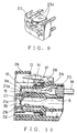
- FIGS 8 to 14 illustrate the second example of the present invention concerned with a male-type connector housing 26 having a front holder 27.
- This connector housing is different in shape from that of the first example, nevertheless the function is the same. Consequently, each part having the same function with that of the corresponding part in the first example is given the same number so that the detailed description of such parts is omitted in the following.
- the sealing member 28 seals the contact surface between the end surface of the body 1a of the female-type connector housing 1 and the connector housing 26, thereby ensuring the waterproof.
- the terminal receiving chamber 5 Similar to the first example, in the connector housing 26, there are formed the terminal receiving chamber 5, the notch 12 which extends from the terminal receiving chamber 5 to the insertion slots 9a and 9b, and the resilient locking arm 13 having the locking projection 14 and the detection end 15 (see Fig. 10).
- the front holder 27 stops at the provisional locking position where the stopper 25 abuts against the stop end 8.
- the holder end 23a of the front holder 27 is located at the position where the surface 23a does not hit against the detection end 15 of the locking arm 13.
- the terminal 29 When the terminal 29 is inserted into the terminal receiving chamber 5, the terminal 29 pushes the locking projection 14 to allow the resilient locking arm 13 to be deformed, causing the detection end 15 to be lowered toward the insertion slot 9a.
- the resilient wall 24 After the complete insertion of the terminal 29, when the front holder 27 is pushed toward the inserting direction from the provisional locking position, the resilient wall 24 is deformed to allow the stopper 25 to run onto the lower surface of the insertion slot 9a, causing the front holder 27 to be lifted up due to the resilient force of the resilient wall 24, that is, the holder end 23a of the front holder 27 is significantly lifted up, similar to the first example.
- the locking hole 17 of the terminal 29 fits with the locking projection 14 of the resilient locking arm 13, that is, the locking arm 13 resiliently recovers to its original shape (see Fig. 13) from its deformed shape (see Fig. 10). Consequently, the front holder 27 can be fully inserted into the insertion slot 9a by pushing from the lifted position as described above (see Fig. 14).
- the fully-inserted holder 27 prevents the locking arm 13 from being deformed downward so that the fitting between the locking hole 17 of the terminal 29 and the locking projection 14 of the resilient locking arm 13 is maintained to prevent the terminal 29 from coming off.
Landscapes
- Details Of Connecting Devices For Male And Female Coupling (AREA)
- Connector Housings Or Holding Contact Members (AREA)
Applications Claiming Priority (2)
| Application Number | Priority Date | Filing Date | Title |
|---|---|---|---|
| JP33384498 | 1998-11-25 | ||
| JP10333844A JP2000164285A (ja) | 1998-11-25 | 1998-11-25 | フロントホルダを有するコネクタ |
Publications (3)
| Publication Number | Publication Date |
|---|---|
| EP1005110A2 true EP1005110A2 (de) | 2000-05-31 |
| EP1005110A3 EP1005110A3 (de) | 2001-09-12 |
| EP1005110B1 EP1005110B1 (de) | 2005-03-16 |
Family
ID=18270585
Family Applications (1)
| Application Number | Title | Priority Date | Filing Date |
|---|---|---|---|
| EP99123528A Expired - Lifetime EP1005110B1 (de) | 1998-11-25 | 1999-11-25 | Steckvebinder mit Verriegelungsglied |
Country Status (6)
| Country | Link |
|---|---|
| US (1) | US6416365B1 (de) |
| EP (1) | EP1005110B1 (de) |
| JP (1) | JP2000164285A (de) |
| AT (1) | ATE291283T1 (de) |
| DE (1) | DE69924213T2 (de) |
| ES (1) | ES2237877T3 (de) |
Cited By (1)
| Publication number | Priority date | Publication date | Assignee | Title |
|---|---|---|---|---|
| EP2544310A1 (de) * | 2011-07-06 | 2013-01-09 | Sumitomo Wiring Systems, Ltd. | Steckverbinder |
Families Citing this family (16)
| Publication number | Priority date | Publication date | Assignee | Title |
|---|---|---|---|---|
| US7491232B2 (en) * | 1998-09-18 | 2009-02-17 | Aptus Endosystems, Inc. | Catheter-based fastener implantation apparatus and methods with implantation force resolution |
| JP3755644B2 (ja) * | 2000-11-01 | 2006-03-15 | 住友電装株式会社 | コネクタ |
| US20050070992A1 (en) | 2001-11-28 | 2005-03-31 | Aptus Endosystems, Inc. | Prosthesis systems and methods sized and configured for the receipt and retention of fasteners |
| US20090112303A1 (en) * | 2001-11-28 | 2009-04-30 | Lee Bolduc | Devices, systems, and methods for endovascular staple and/or prosthesis delivery and implantation |
| JP4405262B2 (ja) | 2001-11-28 | 2010-01-27 | アプタス エンドシステムズ, インコーポレイテッド | 血管内動脈瘤修復システム |
| US20070073389A1 (en) | 2001-11-28 | 2007-03-29 | Aptus Endosystems, Inc. | Endovascular aneurysm devices, systems, and methods |
| US8231639B2 (en) | 2001-11-28 | 2012-07-31 | Aptus Endosystems, Inc. | Systems and methods for attaching a prosthesis within a body lumen or hollow organ |
| US9320503B2 (en) | 2001-11-28 | 2016-04-26 | Medtronic Vascular, Inc. | Devices, system, and methods for guiding an operative tool into an interior body region |
| US20050177180A1 (en) | 2001-11-28 | 2005-08-11 | Aptus Endosystems, Inc. | Devices, systems, and methods for supporting tissue and/or structures within a hollow body organ |
| JP2003257551A (ja) * | 2002-03-07 | 2003-09-12 | Ryosei Electro-Circuit Systems Ltd | コネクタ |
| DE10320665B4 (de) | 2002-05-23 | 2008-11-13 | Sumitomo Wiring Systems, Ltd., Yokkaichi | Verbinder |
| CN101466316B (zh) | 2005-10-20 | 2012-06-27 | 阿普特斯内系统公司 | 包括使用固定件工具的用于修复物递送和植入的装置、系统和方法 |
| CA2740867C (en) | 2008-10-16 | 2018-06-12 | Aptus Endosystems, Inc. | Devices, systems, and methods for endovascular staple and/or prosthesis delivery and implantation |
| JP6195165B2 (ja) * | 2014-03-13 | 2017-09-13 | 住友電装株式会社 | コネクタ |
| CN109216953B (zh) * | 2017-07-04 | 2024-07-16 | 泰科电子(上海)有限公司 | 连接器 |
| JP7592374B2 (ja) * | 2022-11-08 | 2024-12-02 | 矢崎総業株式会社 | 固定構造 |
Family Cites Families (5)
| Publication number | Priority date | Publication date | Assignee | Title |
|---|---|---|---|---|
| JP2651395B2 (ja) * | 1991-10-28 | 1997-09-10 | 矢崎総業株式会社 | コネクタ |
| JP2725754B2 (ja) * | 1993-08-06 | 1998-03-11 | 矢崎総業株式会社 | フロント部材を有するコネクタ |
| EP0730321B1 (de) * | 1995-02-06 | 2002-07-03 | Yazaki Corporation | Verbinder versehen mit einem Bauelement zur Feststellung der Einfügung für Abschlussklemmen aus Metall |
| JPH0945411A (ja) | 1995-07-31 | 1997-02-14 | Yazaki Corp | ホルダ付コネクタ |
| JP3495881B2 (ja) | 1997-05-08 | 2004-02-09 | 矢崎総業株式会社 | コネクタ |
-
1998
- 1998-11-25 JP JP10333844A patent/JP2000164285A/ja active Pending
-
1999
- 1999-11-24 US US09/448,497 patent/US6416365B1/en not_active Expired - Lifetime
- 1999-11-25 EP EP99123528A patent/EP1005110B1/de not_active Expired - Lifetime
- 1999-11-25 ES ES99123528T patent/ES2237877T3/es not_active Expired - Lifetime
- 1999-11-25 DE DE69924213T patent/DE69924213T2/de not_active Expired - Lifetime
- 1999-11-25 AT AT99123528T patent/ATE291283T1/de not_active IP Right Cessation
Cited By (3)
| Publication number | Priority date | Publication date | Assignee | Title |
|---|---|---|---|---|
| EP2544310A1 (de) * | 2011-07-06 | 2013-01-09 | Sumitomo Wiring Systems, Ltd. | Steckverbinder |
| CN102868046A (zh) * | 2011-07-06 | 2013-01-09 | 住友电装株式会社 | 连接器 |
| CN102868046B (zh) * | 2011-07-06 | 2015-01-14 | 住友电装株式会社 | 连接器 |
Also Published As
| Publication number | Publication date |
|---|---|
| EP1005110A3 (de) | 2001-09-12 |
| ES2237877T3 (es) | 2005-08-01 |
| DE69924213T2 (de) | 2006-03-02 |
| US6416365B1 (en) | 2002-07-09 |
| DE69924213D1 (de) | 2005-04-21 |
| JP2000164285A (ja) | 2000-06-16 |
| EP1005110B1 (de) | 2005-03-16 |
| ATE291283T1 (de) | 2005-04-15 |
Similar Documents
| Publication | Publication Date | Title |
|---|---|---|
| EP1005110B1 (de) | Steckvebinder mit Verriegelungsglied | |
| US6638109B2 (en) | Connector with a side retainer | |
| US7572142B2 (en) | Connector | |
| US7722381B2 (en) | Connector | |
| EP1054481A1 (de) | Ein Verbinder | |
| EP2082457B1 (de) | Elektrischer verbinder mit scoop-proof-dom | |
| CN100468878C (zh) | 分开式连接器和连接器组件 | |
| EP1083639A1 (de) | Verbinder | |
| US6045395A (en) | Lock detecting connector | |
| EP0923169A1 (de) | Steckverbinder mit einem Kurzschlusskontakt | |
| EP0978905A2 (de) | Verbinder | |
| US6851987B2 (en) | Connector | |
| JP3112237B2 (ja) | 端子抜止め手段付きコネクタ | |
| US7114999B2 (en) | Connector and a connector assembly | |
| US7402069B2 (en) | Connector | |
| US6048226A (en) | Front holder-incorporating connector | |
| KR100615894B1 (ko) | 커넥터의 하우징 및 이를 이용한 커넥터 | |
| US6786756B2 (en) | Connector | |
| JP3106282B2 (ja) | コネクタ | |
| JPH06124745A (ja) | 端子係止機構付きコネクタ | |
| JP3013718B2 (ja) | コネクタ | |
| EP1150388B1 (de) | Vorrichtung zur Verhinderung von Wackelbewegungen bei einem Anschlusskontakt sowie Verbinder | |
| EP1085612A1 (de) | Verbinder | |
| EP0906644A1 (de) | Verbinder mit lagersicherungsvorrichtung |
Legal Events
| Date | Code | Title | Description |
|---|---|---|---|
| PUAI | Public reference made under article 153(3) epc to a published international application that has entered the european phase |
Free format text: ORIGINAL CODE: 0009012 |
|
| AK | Designated contracting states |
Kind code of ref document: A2 Designated state(s): AT BE CH CY DE DK ES FI FR GB GR IE IT LI LU MC NL PT SE |
|
| AX | Request for extension of the european patent |
Free format text: AL;LT;LV;MK;RO;SI |
|
| PUAL | Search report despatched |
Free format text: ORIGINAL CODE: 0009013 |
|
| AK | Designated contracting states |
Kind code of ref document: A3 Designated state(s): AT BE CH CY DE DK ES FI FR GB GR IE IT LI LU MC NL PT SE |
|
| AX | Request for extension of the european patent |
Free format text: AL;LT;LV;MK;RO;SI |
|
| 17P | Request for examination filed |
Effective date: 20020312 |
|
| AKX | Designation fees paid |
Free format text: AT BE CH CY DE DK ES FI FR GB GR IE IT LI LU MC NL PT SE |
|
| 17Q | First examination report despatched |
Effective date: 20040204 |
|
| GRAP | Despatch of communication of intention to grant a patent |
Free format text: ORIGINAL CODE: EPIDOSNIGR1 |
|
| GRAS | Grant fee paid |
Free format text: ORIGINAL CODE: EPIDOSNIGR3 |
|
| GRAA | (expected) grant |
Free format text: ORIGINAL CODE: 0009210 |
|
| AK | Designated contracting states |
Kind code of ref document: B1 Designated state(s): AT BE CH CY DE DK ES FI FR GB GR IE IT LI LU MC NL PT SE |
|
| PG25 | Lapsed in a contracting state [announced via postgrant information from national office to epo] |
Ref country code: NL Free format text: LAPSE BECAUSE OF FAILURE TO SUBMIT A TRANSLATION OF THE DESCRIPTION OR TO PAY THE FEE WITHIN THE PRESCRIBED TIME-LIMIT Effective date: 20050316 Ref country code: LI Free format text: LAPSE BECAUSE OF FAILURE TO SUBMIT A TRANSLATION OF THE DESCRIPTION OR TO PAY THE FEE WITHIN THE PRESCRIBED TIME-LIMIT Effective date: 20050316 Ref country code: FI Free format text: LAPSE BECAUSE OF FAILURE TO SUBMIT A TRANSLATION OF THE DESCRIPTION OR TO PAY THE FEE WITHIN THE PRESCRIBED TIME-LIMIT Effective date: 20050316 Ref country code: CH Free format text: LAPSE BECAUSE OF FAILURE TO SUBMIT A TRANSLATION OF THE DESCRIPTION OR TO PAY THE FEE WITHIN THE PRESCRIBED TIME-LIMIT Effective date: 20050316 Ref country code: AT Free format text: LAPSE BECAUSE OF FAILURE TO SUBMIT A TRANSLATION OF THE DESCRIPTION OR TO PAY THE FEE WITHIN THE PRESCRIBED TIME-LIMIT Effective date: 20050316 |
|
| REG | Reference to a national code |
Ref country code: GB Ref legal event code: FG4D |
|
| REG | Reference to a national code |
Ref country code: CH Ref legal event code: EP |
|
| REG | Reference to a national code |
Ref country code: SE Ref legal event code: TRGR |
|
| REG | Reference to a national code |
Ref country code: IE Ref legal event code: FG4D |
|
| REF | Corresponds to: |
Ref document number: 69924213 Country of ref document: DE Date of ref document: 20050421 Kind code of ref document: P |
|
| PG25 | Lapsed in a contracting state [announced via postgrant information from national office to epo] |
Ref country code: GR Free format text: LAPSE BECAUSE OF FAILURE TO SUBMIT A TRANSLATION OF THE DESCRIPTION OR TO PAY THE FEE WITHIN THE PRESCRIBED TIME-LIMIT Effective date: 20050616 Ref country code: DK Free format text: LAPSE BECAUSE OF FAILURE TO SUBMIT A TRANSLATION OF THE DESCRIPTION OR TO PAY THE FEE WITHIN THE PRESCRIBED TIME-LIMIT Effective date: 20050616 |
|
| REG | Reference to a national code |
Ref country code: ES Ref legal event code: FG2A Ref document number: 2237877 Country of ref document: ES Kind code of ref document: T3 |
|
| NLV1 | Nl: lapsed or annulled due to failure to fulfill the requirements of art. 29p and 29m of the patents act | ||
| PG25 | Lapsed in a contracting state [announced via postgrant information from national office to epo] |
Ref country code: PT Free format text: LAPSE BECAUSE OF FAILURE TO SUBMIT A TRANSLATION OF THE DESCRIPTION OR TO PAY THE FEE WITHIN THE PRESCRIBED TIME-LIMIT Effective date: 20050907 |
|
| REG | Reference to a national code |
Ref country code: CH Ref legal event code: PL |
|
| PG25 | Lapsed in a contracting state [announced via postgrant information from national office to epo] |
Ref country code: IE Free format text: LAPSE BECAUSE OF NON-PAYMENT OF DUE FEES Effective date: 20051125 Ref country code: CY Free format text: LAPSE BECAUSE OF FAILURE TO SUBMIT A TRANSLATION OF THE DESCRIPTION OR TO PAY THE FEE WITHIN THE PRESCRIBED TIME-LIMIT Effective date: 20051125 |
|
| PG25 | Lapsed in a contracting state [announced via postgrant information from national office to epo] |
Ref country code: MC Free format text: LAPSE BECAUSE OF NON-PAYMENT OF DUE FEES Effective date: 20051130 Ref country code: LU Free format text: LAPSE BECAUSE OF NON-PAYMENT OF DUE FEES Effective date: 20051130 |
|
| ET | Fr: translation filed | ||
| PLBE | No opposition filed within time limit |
Free format text: ORIGINAL CODE: 0009261 |
|
| STAA | Information on the status of an ep patent application or granted ep patent |
Free format text: STATUS: NO OPPOSITION FILED WITHIN TIME LIMIT |
|
| 26N | No opposition filed |
Effective date: 20051219 |
|
| REG | Reference to a national code |
Ref country code: IE Ref legal event code: MM4A |
|
| PGFP | Annual fee paid to national office [announced via postgrant information from national office to epo] |
Ref country code: FR Payment date: 20141110 Year of fee payment: 16 Ref country code: SE Payment date: 20141111 Year of fee payment: 16 Ref country code: ES Payment date: 20141013 Year of fee payment: 16 Ref country code: GB Payment date: 20141119 Year of fee payment: 16 |
|
| PGFP | Annual fee paid to national office [announced via postgrant information from national office to epo] |
Ref country code: IT Payment date: 20141107 Year of fee payment: 16 |
|
| PGFP | Annual fee paid to national office [announced via postgrant information from national office to epo] |
Ref country code: BE Payment date: 20141111 Year of fee payment: 16 |
|
| PGFP | Annual fee paid to national office [announced via postgrant information from national office to epo] |
Ref country code: DE Payment date: 20151118 Year of fee payment: 17 |
|
| GBPC | Gb: european patent ceased through non-payment of renewal fee |
Effective date: 20151125 |
|
| PG25 | Lapsed in a contracting state [announced via postgrant information from national office to epo] |
Ref country code: IT Free format text: LAPSE BECAUSE OF NON-PAYMENT OF DUE FEES Effective date: 20151125 |
|
| REG | Reference to a national code |
Ref country code: FR Ref legal event code: ST Effective date: 20160729 |
|
| PG25 | Lapsed in a contracting state [announced via postgrant information from national office to epo] |
Ref country code: SE Free format text: LAPSE BECAUSE OF NON-PAYMENT OF DUE FEES Effective date: 20151126 |
|
| PG25 | Lapsed in a contracting state [announced via postgrant information from national office to epo] |
Ref country code: GB Free format text: LAPSE BECAUSE OF NON-PAYMENT OF DUE FEES Effective date: 20151125 |
|
| PG25 | Lapsed in a contracting state [announced via postgrant information from national office to epo] |
Ref country code: FR Free format text: LAPSE BECAUSE OF NON-PAYMENT OF DUE FEES Effective date: 20151130 |
|
| REG | Reference to a national code |
Ref country code: ES Ref legal event code: FD2A Effective date: 20161227 |
|
| PG25 | Lapsed in a contracting state [announced via postgrant information from national office to epo] |
Ref country code: ES Free format text: LAPSE BECAUSE OF NON-PAYMENT OF DUE FEES Effective date: 20151126 |
|
| REG | Reference to a national code |
Ref country code: DE Ref legal event code: R119 Ref document number: 69924213 Country of ref document: DE |
|
| PG25 | Lapsed in a contracting state [announced via postgrant information from national office to epo] |
Ref country code: BE Free format text: LAPSE BECAUSE OF NON-PAYMENT OF DUE FEES Effective date: 20151130 |
|
| PG25 | Lapsed in a contracting state [announced via postgrant information from national office to epo] |
Ref country code: DE Free format text: LAPSE BECAUSE OF NON-PAYMENT OF DUE FEES Effective date: 20170601 |