EP1005921A2 - Laminoir à cylindres obliques - Google Patents
Laminoir à cylindres obliques Download PDFInfo
- Publication number
- EP1005921A2 EP1005921A2 EP99306996A EP99306996A EP1005921A2 EP 1005921 A2 EP1005921 A2 EP 1005921A2 EP 99306996 A EP99306996 A EP 99306996A EP 99306996 A EP99306996 A EP 99306996A EP 1005921 A2 EP1005921 A2 EP 1005921A2
- Authority
- EP
- European Patent Office
- Prior art keywords
- rolls
- roll
- backup roll
- work
- hydraulic cylinders
- Prior art date
- Legal status (The legal status is an assumption and is not a legal conclusion. Google has not performed a legal analysis and makes no representation as to the accuracy of the status listed.)
- Granted
Links
Images


Classifications
-
- B—PERFORMING OPERATIONS; TRANSPORTING
- B21—MECHANICAL METAL-WORKING WITHOUT ESSENTIALLY REMOVING MATERIAL; PUNCHING METAL
- B21B—ROLLING OF METAL
- B21B13/00—Metal-rolling stands, i.e. an assembly composed of a stand frame, rolls, and accessories
- B21B13/02—Metal-rolling stands, i.e. an assembly composed of a stand frame, rolls, and accessories with axes of rolls arranged horizontally
- B21B13/023—Metal-rolling stands, i.e. an assembly composed of a stand frame, rolls, and accessories with axes of rolls arranged horizontally the axis of the rolls being other than perpendicular to the direction of movement of the product, e.g. cross-rolling
-
- B—PERFORMING OPERATIONS; TRANSPORTING
- B21—MECHANICAL METAL-WORKING WITHOUT ESSENTIALLY REMOVING MATERIAL; PUNCHING METAL
- B21B—ROLLING OF METAL
- B21B13/00—Metal-rolling stands, i.e. an assembly composed of a stand frame, rolls, and accessories
- B21B13/14—Metal-rolling stands, i.e. an assembly composed of a stand frame, rolls, and accessories having counter-pressure devices acting on rolls to inhibit deflection of same under load; Back-up rolls
Definitions
- the present invention relates to a cross rolling machine for rolling a metal sheet by using a pair of work roll and backup roll on the top side and a pair of work roll and backup roll on the bottom side which are crossed with respect to each other.
- a cross rolling method relating to the present invention has been widely used.
- this cross rolling method for example, as shown in FIGS. 3 and 4, a metal sheet 1001 is rolled to a predetermined thickness in a state in which work rolls 1002 and 1003 and backup rolls 1004 and 1005 are arranged vertically in the opposite sides of the metal sheet 1001, and a pair of the work roll 1002 and the backup roll 1004 on the top side and a pair of the work roll 1003 and the backup roll 1005 on the bottom side are pair crossed with respect to each other.
- the work rolls 1002 and 1003 and the backup rolls 1004 and 1005 are arranged vertically in a housing 1006 of a rolling machine, and the metal sheet 1001 is rolled in the direction of arrow mark A (in the left-to-right direction in FIG. 5) from the entrance side to the delivery side.
- the pair of the work roll 1002 and the backup roll 1004 on the top side are pair crossed as follows:
- a motor (not shown) is transmitted from universal joints on the entrance and delivery sides on the top side to worm reduction gears 1016, 1016 via connecting shafts 1017, 1017, screw rods 1015, 1015 threadedly engaging with fixing nuts advance (entrance side) or retreat (delivery side) while being rotated, by which a work roll chock 1007 and a backup roll chock 1009 are pressed and moved in the direction from entrance side to delivery side at the same time via crossheads 1011 and sliding members 1012.
- the crosshead 1011 is advanced by being pushed out by the screw rod 1015, and retreated by being pulled back by a hydraulic cylinder 1018.
- the pair of the work roll 1003 and the backup roll 1005 on the bottom side are pair crossed as follows: By rotating another motor (not shown) in the direction opposite to the motor for the top side, the connecting shafts 1017, worm reduction gears 1016, screw rods 1015, crossheads 1011, and other elements are operated in the direction opposite to the elements on the top side, by which a work roll chock 1008 and a backup roll chock 1010 are pushed out from the delivery side to the entrance side at the same time.
- pair crossing is effected in the same manner as described above.
- this driving means requires a large number of operating members ranging from the motor to the crosshead and a complicated drive system.
- the housing 1006, which is formed with a groove for the crosshead has low rigidity.
- a work roll chock 1007 (1008) and a backup roll chock 1009 (1010) are pair crossed via crossheads 1011 and sliding members 1012.
- the use of the hydraulic cylinders in the drive system simplifies the operating members and drive system, it is difficult to uniformly transmit the pressing force from the hydraulic cylinders 1019, 1019 on the entrance and delivery sides from the crosshead 1011 to the work roll chock 1007 (1008) and the backup roll chock 1009 (1010).
- the housing 1006 has low rigidity because it is formed with a groove for the crosshead.
- the present invention has been made to solve the above problems, and accordingly an object thereof is to provide a cross rolling machine in which crossheads are disused, and work roll chocks and backup roll chocks are pressed directly by hydraulic cylinders, by which a complicated drive system is simplified and the number of components is reduced, the rigidity of a housing is increased, the accuracy of crossing operation is enhanced, and the economical efficiency is improved.
- the present invention provides a cross rolling machine which rolls a metal sheet to a predetermined thickness in a state in which work rolls and backup rolls are arranged vertically on the opposite sides of the metal sheet, and a pair of the work roll and the backup roll on the top side and a pair of the work roll and the backup roll on the bottom side are pair crossed with respect to each other, characterized in that hydraulic cylinders engaging with the work roll chock are disposed in one set on the entrance and delivery sides each of the rolling machine, and hydraulic cylinders engaging with the backup roll chock are disposed in one set on the entrance side of the rolling machine and in two sets on the delivery side thereof.
- pair cross means that either or both of the top pair and the bottom pair are turned in a horizontal plane, by which the pairs are crossed with respect to each other at a predetermined angle (predetermined cross angle).
- the hydraulic cylinders engaging with the backup roll chock may be disposed in two sets on the entrance side of the rolling machine and in one set on the delivery side thereof.
- the backup roll chock may be moved to a position for positioning at a predetermined cross angle by the two sets of hydraulic cylinders disposed on the entrance or delivery side of the rolling machine, and may be pressed and fixed by the one set of hydraulic cylinder disposed on the entrance or delivery side on the other side.
- the configuration may be such that when the backup roll chock is moved to the position for positioning, the second hydraulic cylinders engaging with the backup roll chock are operated in synchronism with the first hydraulic cylinder engaging with the chock for the work roll paired with the backup roll.
- the configuration may be such that screws are disposed in place of the hydraulic cylinders for performing the positioning at the predetermined cross angle, and the positioning at the predetermined cross angle is performed by turning the screws. That is to say, the top paired chocks are moved to the position for positioning at the same time, and the bottom paired chocks are moved to the position for positioning at the same time.
- the cross rolling machine in accordance with the present invention which rolls a metal sheet to a predetermined thickness in a state in which work rolls and backup rolls are arranged vertically on the opposite sides of the metal sheet, and a pair of the work roll and the backup roll on the top side and a pair of the work roll and the backup roll on the bottom side are pair crossed with respect to each other, is also characterized in that hydraulic cylinders engaging with work roll chock are disposed in one set on the entrance and delivery sides each of the rolling machine, and hydraulic cylinders engaging with backup roll chock are disposed in two sets on the entrance and delivery sides each of the rolling machine.
- the backup roll chock may be moved to a position for positioning at a predetermined cross angle by the two sets of hydraulic cylinders disposed on the entrance or delivery side of the rolling machine, and may be pressed and fixed by the two sets of hydraulic cylinders disposed on the entrance or delivery side on the other side.
- the configuration may be such that when the backup roll chock is moved to the position for positioning, the second hydraulic cylinders engaging with the backup roll chock are operated in synchronism with the first hydraulic cylinder engaging with the chock for the work roll paired with the backup roll. That is to say, the top paired chocks are moved to the position for positioning at the same time, and the bottom paired chocks are moved to the position for positioning at the same time.
- the configuration may be such that screws are disposed in place of the hydraulic cylinders for performing the positioning at the predetermined cross angle, and the positioning at the predetermined cross angle is performed by turning the screws.
- the present invention achieves excellent effects as described below.
- the cross rolling machine in accordance with the present invention which rolls a metal sheet to a predetermined thickness in a state in which work rolls and backup rolls are arranged vertically on the opposite sides of the metal sheet, and a pair of the work roll and the backup roll on the top side and a pair of the work roll and the backup roll on the bottom side are pair crossed with respect to each other, is characterized in that first liquid-operated cylinders engaging with top and bottom work roll chocks and second liquid-operated cylinders engaging with top and bottom backup roll chocks are disposed on the entrance and delivery sides of the metal sheet. Therefore, the drive system can be simplified and the number of components can be reduced, and the economical efficiency can be improved.
- the cross rolling machine in accordance with the present invention is characterized in that first hydraulic cylinders engaging with top and bottom work roll chocks are disposed in one set on the entrance and delivery sides each of the metal sheet, and second hydraulic cylinders engaging with top and bottom backup roll chocks are disposed in two sets on one side and in one set on the other side of the entrance and delivery sides of the metal sheet. Therefore, the drive system can be simplified and the number of components can be reduced, the economical efficiency can be improved, and also the strength of the machine can be increased. Further, since two sets of hydraulic cylinders are disposed on one side and one set thereof on the other side, the tilting and falling-down of the backup roll chock can be prevented.
- the backup roll chock is moved to a position for positioning at a predetermined cross angle by the two sets of hydraulic cylinders disposed on one side of the second hydraulic cylinders, and is pressed and fixed by the one set of hydraulic cylinder disposed on the other side, since the positioning and fixing are performed by the hydraulic cylinders, the components can further be simplified, the work efficiency for the pair crossing operation can be increased, and the time taken for pair crossing at the predetermined cross angle can be shortened.
- the cross rolling machine in accordance with the present invention is characterized in that first hydraulic cylinders engaging with top and bottom work roll chocks are disposed in one set on the entrance and delivery sides each of the metal sheet, and second hydraulic cylinders engaging with top and bottom backup roll chocks are disposed in two sets on the entrance and delivery sides each of the metal sheet. Therefore, the drive system can be simplified and the number of components can be reduced, the economical efficiency can be improved, and the strength of the machine can be increased. Also, even if the reduction load is high, the backup roll chock can be supported securely from both sides, so that the tilting and falling-down of the backup roll chock can be prevented.
- the configuration is such that the backup roll chock is moved to a position for positioning at a predetermined cross angle by the two sets of hydraulic cylinders disposed on one side of the second hydraulic cylinders, and is pressed and fixed by the two sets of hydraulic cylinder disposed on the other side, since the positioning and fixing are performed by the hydraulic cylinders, the components can further be simplified, the work efficiency for the pair crossing operation can be increased, and the time taken for pair crossing at the predetermined cross angle can be shortened.
- the positioning operation can be performed smoothly, and the time taken for pair crossing can further be shortened.
- the configuration is such that screws are disposed in place of the second hydraulic cylinders for moving the backup roll chock to the position for positioning, and the backup roll chock is moved to the position for positioning at the predetermined cross angle by turning the screws, the accuracy of positioning can be enhanced, the whole system can further be simplified, and the economical efficiency can further be improved.
- a top work roll 21 and a top backup roll 41 are arranged on the top side of a metal sheet 1 being rolled, and a bottom work roll 31 and a bottom backup roll 51 are arranged on the bottom side of the metal sheet 1.
- the opposite ends of the top work roll 21 are rotatably held by top work roll chocks 22, those of the top backup roll 41 by top backup roll chocks 42, those of the bottom work roll 31 by bottom work roll chocks 32, and those of the bottom backup roll 51 by bottom backup roll chocks 52.
- the metal sheet 1 moves in the left-to-right direction in FIG. 1, thereby being rolled by the top work roll 21 and the bottom work roll 31.
- the top work roll 21 has a diameter smaller than that of the top backup roll 41
- the bottom work roll 31 has a diameter smaller than that of the bottom backup roll 51.
- a set of cross drive member 23 is disposed, and on the delivery side (right side in FIG. 1) thereof, a set of cross drive member 24 is disposed.
- a set of cross drive member 33 is disposed, and on the delivery side thereof, a set of cross drive member 34 is disposed.
- a set of cross drive member 43 is disposed, and on the delivery side thereof, two sets of cross drive members 44 are disposed.
- a set of cross drive member 53 is disposed, and on the delivery side thereof, two sets of cross drive members 54 are disposed.
- the cross drive members 23, 24, 33, 34, 43, 44, 53 and 54 have the same basic configuration, each being provided with a sliding member, a pressing member, a piston rod, and a hydraulic cylinder.
- the cross drive member 23 is provided with a pressing member 231, a sliding member 232, a piston rod 233, and a hydraulic cylinder 234, and the cross drive member 24 is provided with a pressing member 241, a sliding member 242, a piston rod 243, and a hydraulic cylinder 244.
- the cross drive member 33 is provided with a pressing member 331, a sliding member 332, a piston rod 333, and a hydraulic cylinder 334
- the cross drive member 34 is provided with a pressing member 341, a sliding member 342, a piston rod 343, and a hydraulic cylinder 344
- the cross drive member 43 is provided with a pressing member 431, a sliding member 432, a piston rod 433, and a hydraulic cylinder 434
- the cross drive member 44 is provided with a pressing member 441, a sliding member 442, a piston rod 443, and a hydraulic cylinder 444.
- the cross drive member 53 is provided with a pressing member 531, a sliding member 532, a piston rod 533, and a hydraulic cylinder 534
- the cross drive member 54 is provided with a pressing member 541, a sliding member 542, a piston rod 543, and a hydraulic cylinder 544.
- the body of the hydraulic cylinder 234 is attached to the housing 6, and the piston rod 233 is mounted in such a manner as to project and retract.
- the pressing member 231 which transmits the pressing force from the hydraulic cylinder 234 to the top work roll chock 22, is fixed to the distal end of the piston rod 233.
- the sliding member 232 which is made of a material easy to slide at the time of vertical movement, is fixed to the outside (opposite side to a face to which the piston rod 233 is fixed) of the pressing member 231.
- the hydraulic cylinder 234 is connected to control means (not shown).
- This control means carries out speed control, direction control, and pressure control of the piston rod 233.
- various control circuits commonly used may be used.
- the hydraulic cylinder 244 and the hydraulic cylinders 444, 444 on the delivery side are operated in synchronism to move the pressing members 241, and 441, 441 on the delivery side in the direction of delivery side to a position where a predetermined cross angle is obtained, by which the pressing members 241 and 441, 441 on the delivery side are positioned.
- the hydraulic cylinder 234 and the hydraulic cylinder 434 on the entrance side are operated to move the pressing members 231 and 431 on the entrance side in the direction of delivery side, by which the top work roll chock 22 and the top backup roll chock 42 are pressed on the pressing members 241 and 441, 441 on the delivery side, respectively.
- the top work roll chock 22 and the top backup roll chock 42 are fixed at the predetermined cross angle. Specifically, the positions are set by the pressing members 241 and 441, 441 on the delivery side, and the top work roll chock 22 and the top backup roll chock 42 are moved to the set positions and pressed by the pressing members 231 and 431 on the entrance side, respectively, by which the chocks 22 and 42 are fixed.
- the pair of the bottom work roll 31 and the bottom backup roll 51 are moved in the direction (direction of entrance side) opposite to the direction in which the top pair moves (direction of delivery side).
- the hydraulic cylinder 344 and the hydraulic cylinders 544, 544 on the delivery side are operated in synchronism to move the pressing members 341 and 541, 541 on the delivery side in the direction of entrance side to a position where the predetermined cross angle is obtained, by which the pressing members 341 and 541, 541 on the delivery side are positioned.
- the bottom work roll chock 32 and the bottom backup roll chock 52 are also positioned.
- the hydraulic cylinder 334 and the hydraulic cylinder 534 on the entrance side are operated so that the pressure acts in the direction of delivery side.
- the pressing members 331 and 531 on the entrance side press the bottom work roll chock 32 and the bottom backup roll chock 52, respectively, in the direction of delivery side, and thereby the chocks 32 and 52 are fixed at the predetermined cross angle. That is to say, the bottom work roll chock 32 and the bottom backup roll chock 52 are moved to the set position by the pressing members 341 and 541, 541 on the delivery side, and are pressed and fixed by the pressing members 331 and 531 on the entrance side.
- the pair of the top work roll 21 and the top backup roll 41 and the pair of the bottom work roll 31 and the bottom backup roll 51 are pair crossed with respect to each other.
- each of the chocks is moved vertically (in the direction of top and bottom in FIG. 1) by a reduction load or the like during the operation of the rolling machine, the chock slides with respect to the side face of each of the sliding members.
- the sliding members 232 and 242 slide on the side faces of the top work roll chock 22, and the sliding members 432 and 442, 442 slide on the side faces of the top backup roll chock 42.
- one hydraulic cylinder is disposed on the entrance side of the backup roll chock, and the pressing force from each of the hydraulic cylinders is applied directly to the chock so that the work rolls and the backup rolls are moved so as to be crossed with respect to each other in pairs. Therefore, in this embodiment, the conventionally used crosshead is disused, and the work roll chock and the backup roll chock are pressed directly by the hydraulic cylinders, so that the drive system can be simplified and the number of components can be reduced as compared with the conventional cross rolling machine, whereby the economical efficiency of the rolling machine can be improved. Also, the absence of a groove for crosshead increases the rigidity of housing, thereby improving the structural strength of the rolling machine. Further, since the hydraulic cylinders engaging with the backup roll chock are disposed in one set on one side and in two sets on the other side, the tilting and falling-down of the chock can be prevented.
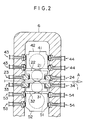
- FIG. 2 the same reference numerals as those in FIG. 1 are applied to the same elements as those of the first embodiment, and the reference numerals of the elements constituting the cross drive member are omitted.
- the explanation common to that of the first embodiment is omitted.
- another set of cross drive member 43 is added to the entrance side of the top backup roll chock 42 of the first embodiment.
- another set of hydraulic cylinder 434 engaging with the top backup roll chock 42 is provided on the entrance side, and other configurations are the same as those of the first embodiment.
- the cross drive members 23 and 24 are disposed in one set each on the entrance and delivery sides of the top work roll chock 22, and the cross drive members 33 and 34 are disposed in one set each on the entrance and delivery sides of the bottom work roll chock 32.
- the cross drive members 43, 43, 44, 44 are disposed in two sets each on the entrance and delivery sides of the top backup roll chock 42, and the cross drive members 53, 53, 54, 54 are disposed in two sets each on the entrance and delivery sides of the bottom backup roll chock 52.
- the cross drive members 23, 24, 33, 34, 43, 44, 53 and 54 each comprises the sliding member, pressing member, piston rod, and hydraulic cylinder as in the case of the first embodiment, and also are operated in the same way as in the case of the first embodiment. Thereby, the positioning at a predetermined angle is performed, and the chocks are fixed at the predetermined cross angle by the pressing forces.
- the two sets, upper and lower, of hydraulic cylinders 444, 444 engaging with the delivery side of the top backup roll chock 42 and the hydraulic cylinder 244 engaging with the delivery side of the top work roll chock 22 are operated in synchronism to move the pressing members 441, 441, and 241 in the direction of delivery side to a position of the predetermined cross angle so that these pressing members are positioned.
- the hydraulic cylinders 434, 434, and 234 on the opposite side (entrance side) are operated to move the pressing members 431, 431, and 231 in the direction of delivery side.
- the operation is performed in the direction opposite to the case of top side.
- the two sets, upper and lower, of hydraulic cylinders 544, 544 engaging with the delivery side of the bottom backup roll chock 52 and the hydraulic cylinder 344 engaging with the delivery side of the bottom work roll chock 32 are operated in synchronism to move the pressing members 541, 541, and 341 in the direction of entrance side to a position of the predetermined cross angle so that these pressing members are positioned.
- the hydraulic cylinders 534, 534, and 334 on the opposite side (entrance side) are operated to move the pressing members 531, 531, and 331 in the direction of delivery side.
- the hydraulic cylinders 434 and 444 engaging with the top backup roll chock 42 and the hydraulic cylinders 534 and 544 engaging with the bottom backup roll chock 52 are disposed in two sets on the entrance side and in two sets on the delivery side. Therefore, even when the reduction load is high, the top backup roll chock 42 and the bottom backup roll chock 52 can be supported securely from both sides, so that the tilting and falling-down of the top backup roll chock 42 and the bottom backup roll chock 52 can be prevented.
- the top backup roll chock 42 and the bottom backup roll chock 52 can be supported securely from both sides, so that the tilting and falling-down of the top backup roll chock 42 and the bottom backup roll chock 52 can be prevented.
- a screw may be used in place of the hydraulic cylinder to perform positioning. Specifically, by turning this screw, the positioning at a predetermined angle is performed. This screw acts as a feed screw. By this configuration, the positioning accuracy can be improved, and the components of the machine can be simplified.
- the number of cross drive members is not limited to this, and more than two sets of cross drive members may be disposed. In this case, the equal number of cross drive members need not be disposed on the entrance and delivery sides. At least a plurality of sets of cross drive members (hydraulic cylinders) for positioning are disposed.
- the hydraulic cylinder may be of a single or double acting type, or may be of a multistage type.
- the hydraulic cylinder is used in the above embodiments, the cylinder is not limited to this type, and a liquid-operated cylinder, which uses a liquid as the working medium, may be used. In this case, for example, water is used as the working medium.
- the invention provides a cross rolling machine for rolling a metal sheet to a predetermined thickness, the machine comprising upper and lower work rolls and upper and lower back up rolls, the upper and lower rolls being disposed above and below the plane of the metal sheet respectively, the ends of the work rolls being rotatably supported in work roll support chocks and the ends of the back-up rolls being rotatably supported in back-up roll support chocks; the upper work roll and lower work roll being able to have their axes about which the rolls rotate crossed with respect to each other at a predetermined angle, the work rolls and back-up rolls and their support chocks being movably located in a rolling mill housing, the housing having at least frame members adjacent the roll ends and in which the support chocks are movably located; the ends of the upper work rolls and back-up rolls and the lower work rolls and back-up rolls on each side of the housing being mutually displaceable horizontally within their respective housing frame members with respect to a vertical plane by drive means to move and locate the work roll and
Landscapes
- Engineering & Computer Science (AREA)
- Mechanical Engineering (AREA)
- Metal Rolling (AREA)
- Control Of Metal Rolling (AREA)
- Crushing And Grinding (AREA)
- Drilling And Exploitation, And Mining Machines And Methods (AREA)
- Reduction Rolling/Reduction Stand/Operation Of Reduction Machine (AREA)
Applications Claiming Priority (2)
| Application Number | Priority Date | Filing Date | Title |
|---|---|---|---|
| JP34540598A JP3285833B2 (ja) | 1998-12-04 | 1998-12-04 | クロスロール圧延機 |
| JP34540598 | 1998-12-04 |
Publications (3)
| Publication Number | Publication Date |
|---|---|
| EP1005921A2 true EP1005921A2 (fr) | 2000-06-07 |
| EP1005921A3 EP1005921A3 (fr) | 2000-08-30 |
| EP1005921B1 EP1005921B1 (fr) | 2003-10-15 |
Family
ID=18376380
Family Applications (1)
| Application Number | Title | Priority Date | Filing Date |
|---|---|---|---|
| EP99306996A Expired - Lifetime EP1005921B1 (fr) | 1998-12-04 | 1999-09-03 | Laminoir à cylindres obliques |
Country Status (8)
| Country | Link |
|---|---|
| US (1) | US6266988B1 (fr) |
| EP (1) | EP1005921B1 (fr) |
| JP (1) | JP3285833B2 (fr) |
| KR (1) | KR100347619B1 (fr) |
| CN (1) | CN1129491C (fr) |
| AT (1) | ATE251956T1 (fr) |
| CA (1) | CA2279920C (fr) |
| DE (1) | DE69912076T2 (fr) |
Cited By (1)
| Publication number | Priority date | Publication date | Assignee | Title |
|---|---|---|---|---|
| WO2001012353A1 (fr) * | 1999-08-11 | 2001-02-22 | Mitsubishi Heavy Industries, Ltd. | Laminoir |
Families Citing this family (6)
| Publication number | Priority date | Publication date | Assignee | Title |
|---|---|---|---|---|
| JP3525870B2 (ja) | 2000-07-17 | 2004-05-10 | Jfeスチール株式会社 | ロールクロス圧延機のクロスヘッド加工方法及び装置 |
| DE102008009902A1 (de) * | 2008-02-19 | 2009-08-27 | Sms Demag Ag | Walzvorrichtung, insbesondere Schubwalzengerüst |
| JP5491090B2 (ja) * | 2009-07-22 | 2014-05-14 | 三菱日立製鉄機械株式会社 | 圧延機及びそれを備えたタンデム圧延機 |
| JP5957341B2 (ja) * | 2012-08-31 | 2016-07-27 | Primetals Technologies Japan株式会社 | 熱延鋼板の製造設備 |
| CN110421011B (zh) * | 2019-08-16 | 2024-07-05 | 中冶南方工程技术有限公司 | 用于18辊轧机侧支承装置的标定装置及标定方法 |
| WO2021220366A1 (fr) * | 2020-04-27 | 2021-11-04 | Primetals Technologies Japan 株式会社 | Laminoir à chaud et procédé de laminage à chaud |
Family Cites Families (18)
| Publication number | Priority date | Publication date | Assignee | Title |
|---|---|---|---|---|
| US1860931A (en) * | 1928-02-23 | 1932-05-31 | Bethlehem Steel Corp | Rolling mill |
| JPS5454949A (en) * | 1977-10-08 | 1979-05-01 | Ishikawajima Harima Heavy Ind Co Ltd | Rolling method and apparatus for multistage rolling mill |
| JPS57190712A (en) * | 1981-05-20 | 1982-11-24 | Mitsubishi Heavy Ind Ltd | Movable roll chock retaining device in cross roll rolling mill |
| JPS60111702A (ja) * | 1983-11-24 | 1985-06-18 | Mitsubishi Heavy Ind Ltd | クロスロ−ル圧延機 |
| JPS60210306A (ja) * | 1984-04-02 | 1985-10-22 | Mitsubishi Heavy Ind Ltd | クロスロ−ル式圧延機 |
| JPH0773731B2 (ja) * | 1985-08-09 | 1995-08-09 | 三菱重工業株式会社 | ロールクロスミル |
| JPS62162512A (ja) * | 1986-01-14 | 1987-07-18 | Toray Ind Inc | 繊維強化樹脂成形用金型装置 |
| JPH0618646B2 (ja) * | 1986-05-12 | 1994-03-16 | 三菱重工業株式会社 | ロ−ルクロス式圧延機 |
| GB2195279B (en) * | 1986-09-24 | 1990-05-23 | Davy Mckee | Improvements in rolling mills |
| DE4010662C3 (de) * | 1990-04-03 | 2001-07-05 | Bwg Bergwerk Walzwerk | Anstellvorrichtung zum Einstellen des Walzenabstandes in Walzgerüsten, insbesondere in Bandwalzgerüsten für Warm- oder Kaltwalzung |
| JP2575982B2 (ja) * | 1992-01-16 | 1997-01-29 | 三菱重工業株式会社 | 金属板表面の光沢付与方法 |
| JPH05237511A (ja) * | 1992-02-28 | 1993-09-17 | Ishikawajima Harima Heavy Ind Co Ltd | 圧延機 |
| JP2961010B2 (ja) * | 1992-05-13 | 1999-10-12 | 三菱重工業株式会社 | クロスロール圧延機 |
| JPH0631304A (ja) * | 1992-06-11 | 1994-02-08 | Ishikawajima Harima Heavy Ind Co Ltd | クロスミル |
| DE69312223T2 (de) * | 1992-11-10 | 1998-02-19 | Mitsubishi Heavy Ind Ltd | Verfahren zur Glanzbearbeitung von Blechoberflächen und Verfahren zum Kaltwalzen von metallischen Materialien |
| JPH0760309A (ja) * | 1993-08-26 | 1995-03-07 | Mitsubishi Heavy Ind Ltd | 圧延機及び帯材の圧延方法 |
| JP2999106B2 (ja) * | 1993-11-10 | 2000-01-17 | 三菱重工業株式会社 | 圧延方法 |
| JPH09220608A (ja) * | 1996-02-14 | 1997-08-26 | Sumitomo Metal Ind Ltd | クロスロール圧延機のロール制御方法 |
-
1998
- 1998-12-04 JP JP34540598A patent/JP3285833B2/ja not_active Expired - Fee Related
-
1999
- 1999-04-26 KR KR1019990014862A patent/KR100347619B1/ko not_active Expired - Lifetime
- 1999-08-09 CA CA002279920A patent/CA2279920C/fr not_active Expired - Fee Related
- 1999-08-25 CN CN99118093A patent/CN1129491C/zh not_active Expired - Lifetime
- 1999-09-03 AT AT99306996T patent/ATE251956T1/de active
- 1999-09-03 EP EP99306996A patent/EP1005921B1/fr not_active Expired - Lifetime
- 1999-09-03 DE DE69912076T patent/DE69912076T2/de not_active Expired - Lifetime
- 1999-12-03 US US09/454,104 patent/US6266988B1/en not_active Expired - Lifetime
Cited By (2)
| Publication number | Priority date | Publication date | Assignee | Title |
|---|---|---|---|---|
| WO2001012353A1 (fr) * | 1999-08-11 | 2001-02-22 | Mitsubishi Heavy Industries, Ltd. | Laminoir |
| US6510721B1 (en) | 1999-08-11 | 2003-01-28 | Mitsubishi Heavy Industries, Ltd. | Rolling mill |
Also Published As
| Publication number | Publication date |
|---|---|
| CA2279920C (fr) | 2004-08-31 |
| US6266988B1 (en) | 2001-07-31 |
| JP3285833B2 (ja) | 2002-05-27 |
| CN1129491C (zh) | 2003-12-03 |
| EP1005921B1 (fr) | 2003-10-15 |
| KR100347619B1 (ko) | 2002-08-09 |
| ATE251956T1 (de) | 2003-11-15 |
| DE69912076T2 (de) | 2004-07-08 |
| JP2000167605A (ja) | 2000-06-20 |
| EP1005921A3 (fr) | 2000-08-30 |
| DE69912076D1 (de) | 2003-11-20 |
| CA2279920A1 (fr) | 2000-06-04 |
| KR20000047388A (ko) | 2000-07-25 |
| CN1256177A (zh) | 2000-06-14 |
Similar Documents
| Publication | Publication Date | Title |
|---|---|---|
| JP2862439B2 (ja) | クロスロール圧延機のロールクロス装置 | |
| EP0094104B1 (fr) | Laminoir et méthode pour laminer des tôles | |
| US4615202A (en) | Six-high rolling stand | |
| US4499748A (en) | Rolling mill | |
| US4922779A (en) | Slitting shears | |
| US4348952A (en) | Cross axis mechanism | |
| EP1005921B1 (fr) | Laminoir à cylindres obliques | |
| US6412323B2 (en) | Cross-roll straightener | |
| EP1107835A1 (fr) | Cage de laminoir dotee de cylindres d'appui et/ou de travail croises | |
| EP0149247B1 (fr) | Laminoir | |
| US6085567A (en) | Rolling stand having crossed rolls with variable setting | |
| EP0313610B1 (fr) | Cage de laminoir | |
| US3699794A (en) | Universal rolling mill stand having more than one caliber for rolling profiles beams such as i-beams | |
| JPH10175006A (ja) | 圧延機のロールクロス機構 | |
| RU2189286C2 (ru) | Многофункциональная клеть прокатного стана для прокатки двутавровой широкополочной балки и способ прокатки двутавровой широкополочной балки с помощью многофункциональной клети прокатного стана | |
| JP4425489B2 (ja) | 多段圧延機 | |
| US4959987A (en) | Rolling mill stand with manipulator | |
| SU1581395A1 (ru) | Прокатна клеть с многовалковым калибром | |
| US3318131A (en) | Multiple-roll rolling mill for exchangeable work rolls of substantially varying diameter | |
| JP3394969B2 (ja) | H形鋼用ローラ矯正装置 | |
| JP3067401B2 (ja) | 水平圧延機 | |
| EP1500442B1 (fr) | Dispositif de cintrage pour les cylindres d'une cage de laminoir à plusieurs cylindres | |
| JP2649292B2 (ja) | 圧延機 | |
| JPH01133605A (ja) | クロスロール式圧延機のロールクロス設定方法 | |
| JPS6167508A (ja) | 粗圧延機 |
Legal Events
| Date | Code | Title | Description |
|---|---|---|---|
| PUAI | Public reference made under article 153(3) epc to a published international application that has entered the european phase |
Free format text: ORIGINAL CODE: 0009012 |
|
| 17P | Request for examination filed |
Effective date: 19990910 |
|
| AK | Designated contracting states |
Kind code of ref document: A2 Designated state(s): AT DE FR GB IT |
|
| AX | Request for extension of the european patent |
Free format text: AL;LT;LV;MK;RO;SI |
|
| PUAL | Search report despatched |
Free format text: ORIGINAL CODE: 0009013 |
|
| AK | Designated contracting states |
Kind code of ref document: A3 Designated state(s): AT BE CH CY DE DK ES FI FR GB GR IE IT LI LU MC NL PT SE |
|
| AX | Request for extension of the european patent |
Free format text: AL;LT;LV;MK;RO;SI |
|
| AKX | Designation fees paid |
Free format text: AT DE FR GB IT |
|
| 17Q | First examination report despatched |
Effective date: 20020806 |
|
| GRAH | Despatch of communication of intention to grant a patent |
Free format text: ORIGINAL CODE: EPIDOS IGRA |
|
| GRAS | Grant fee paid |
Free format text: ORIGINAL CODE: EPIDOSNIGR3 |
|
| GRAA | (expected) grant |
Free format text: ORIGINAL CODE: 0009210 |
|
| AK | Designated contracting states |
Kind code of ref document: B1 Designated state(s): AT DE FR GB IT |
|
| REG | Reference to a national code |
Ref country code: GB Ref legal event code: FG4D |
|
| REF | Corresponds to: |
Ref document number: 69912076 Country of ref document: DE Date of ref document: 20031120 Kind code of ref document: P |
|
| ET | Fr: translation filed | ||
| PLBE | No opposition filed within time limit |
Free format text: ORIGINAL CODE: 0009261 |
|
| STAA | Information on the status of an ep patent application or granted ep patent |
Free format text: STATUS: NO OPPOSITION FILED WITHIN TIME LIMIT |
|
| 26N | No opposition filed |
Effective date: 20040716 |
|
| PGFP | Annual fee paid to national office [announced via postgrant information from national office to epo] |
Ref country code: FR Payment date: 20050823 Year of fee payment: 7 |
|
| PGFP | Annual fee paid to national office [announced via postgrant information from national office to epo] |
Ref country code: GB Payment date: 20050831 Year of fee payment: 7 |
|
| GBPC | Gb: european patent ceased through non-payment of renewal fee |
Effective date: 20060903 |
|
| REG | Reference to a national code |
Ref country code: FR Ref legal event code: ST Effective date: 20070531 |
|
| PG25 | Lapsed in a contracting state [announced via postgrant information from national office to epo] |
Ref country code: GB Free format text: LAPSE BECAUSE OF NON-PAYMENT OF DUE FEES Effective date: 20060903 |
|
| PG25 | Lapsed in a contracting state [announced via postgrant information from national office to epo] |
Ref country code: FR Free format text: LAPSE BECAUSE OF NON-PAYMENT OF DUE FEES Effective date: 20061002 |
|
| PGFP | Annual fee paid to national office [announced via postgrant information from national office to epo] |
Ref country code: DE Payment date: 20180821 Year of fee payment: 20 Ref country code: IT Payment date: 20180919 Year of fee payment: 20 |
|
| PGFP | Annual fee paid to national office [announced via postgrant information from national office to epo] |
Ref country code: AT Payment date: 20180828 Year of fee payment: 20 |
|
| REG | Reference to a national code |
Ref country code: DE Ref legal event code: R071 Ref document number: 69912076 Country of ref document: DE |
|
| REG | Reference to a national code |
Ref country code: AT Ref legal event code: MK07 Ref document number: 251956 Country of ref document: AT Kind code of ref document: T Effective date: 20190903 |