EP1005963A2 - Dispositif de poinçonnage ayant des poinçons remplaçables - Google Patents
Dispositif de poinçonnage ayant des poinçons remplaçables Download PDFInfo
- Publication number
- EP1005963A2 EP1005963A2 EP99112221A EP99112221A EP1005963A2 EP 1005963 A2 EP1005963 A2 EP 1005963A2 EP 99112221 A EP99112221 A EP 99112221A EP 99112221 A EP99112221 A EP 99112221A EP 1005963 A2 EP1005963 A2 EP 1005963A2
- Authority
- EP
- European Patent Office
- Prior art keywords
- stamp
- punching device
- coupling
- punching
- drive
- Prior art date
- Legal status (The legal status is an assumption and is not a legal conclusion. Google has not performed a legal analysis and makes no representation as to the accuracy of the status listed.)
- Granted
Links
Images


Classifications
-
- H—ELECTRICITY
- H05—ELECTRIC TECHNIQUES NOT OTHERWISE PROVIDED FOR
- H05K—PRINTED CIRCUITS; CASINGS OR CONSTRUCTIONAL DETAILS OF ELECTRIC APPARATUS; MANUFACTURE OF ASSEMBLAGES OF ELECTRICAL COMPONENTS
- H05K3/00—Apparatus or processes for manufacturing printed circuits
- H05K3/0011—Working of insulating substrates or insulating layers
- H05K3/0044—Mechanical working of the substrate, e.g. drilling or punching
- H05K3/005—Punching of holes
-
- B—PERFORMING OPERATIONS; TRANSPORTING
- B26—HAND CUTTING TOOLS; CUTTING; SEVERING
- B26F—PERFORATING; PUNCHING; CUTTING-OUT; STAMPING-OUT; SEVERING BY MEANS OTHER THAN CUTTING
- B26F1/00—Perforating; Punching; Cutting-out; Stamping-out; Apparatus therefor
- B26F1/02—Perforating by punching, e.g. with relatively-reciprocating punch and bed
- B26F1/04—Perforating by punching, e.g. with relatively-reciprocating punch and bed with selectively-operable punches
-
- B—PERFORMING OPERATIONS; TRANSPORTING
- B28—WORKING CEMENT, CLAY, OR STONE
- B28B—SHAPING CLAY OR OTHER CERAMIC COMPOSITIONS; SHAPING SLAG; SHAPING MIXTURES CONTAINING CEMENTITIOUS MATERIAL, e.g. PLASTER
- B28B11/00—Apparatus or processes for treating or working the shaped or preshaped articles
- B28B11/12—Apparatus or processes for treating or working the shaped or preshaped articles for removing parts of the articles by cutting
-
- B—PERFORMING OPERATIONS; TRANSPORTING
- B26—HAND CUTTING TOOLS; CUTTING; SEVERING
- B26F—PERFORATING; PUNCHING; CUTTING-OUT; STAMPING-OUT; SEVERING BY MEANS OTHER THAN CUTTING
- B26F2210/00—Perforating, punching, cutting-out, stamping-out, severing by means other than cutting of specific products
- B26F2210/08—Perforating, punching, cutting-out, stamping-out, severing by means other than cutting of specific products of ceramic green sheets, printed circuit boards and the like
-
- H—ELECTRICITY
- H05—ELECTRIC TECHNIQUES NOT OTHERWISE PROVIDED FOR
- H05K—PRINTED CIRCUITS; CASINGS OR CONSTRUCTIONAL DETAILS OF ELECTRIC APPARATUS; MANUFACTURE OF ASSEMBLAGES OF ELECTRICAL COMPONENTS
- H05K1/00—Printed circuits
- H05K1/02—Details
- H05K1/03—Use of materials for the substrate
- H05K1/0306—Inorganic insulating substrates, e.g. ceramic, glass
-
- Y—GENERAL TAGGING OF NEW TECHNOLOGICAL DEVELOPMENTS; GENERAL TAGGING OF CROSS-SECTIONAL TECHNOLOGIES SPANNING OVER SEVERAL SECTIONS OF THE IPC; TECHNICAL SUBJECTS COVERED BY FORMER USPC CROSS-REFERENCE ART COLLECTIONS [XRACs] AND DIGESTS
- Y10—TECHNICAL SUBJECTS COVERED BY FORMER USPC
- Y10T—TECHNICAL SUBJECTS COVERED BY FORMER US CLASSIFICATION
- Y10T83/00—Cutting
- Y10T83/869—Means to drive or to guide tool
- Y10T83/8727—Plural tools selectively engageable with single drive
-
- Y—GENERAL TAGGING OF NEW TECHNOLOGICAL DEVELOPMENTS; GENERAL TAGGING OF CROSS-SECTIONAL TECHNOLOGIES SPANNING OVER SEVERAL SECTIONS OF THE IPC; TECHNICAL SUBJECTS COVERED BY FORMER USPC CROSS-REFERENCE ART COLLECTIONS [XRACs] AND DIGESTS
- Y10—TECHNICAL SUBJECTS COVERED BY FORMER USPC
- Y10T—TECHNICAL SUBJECTS COVERED BY FORMER US CLASSIFICATION
- Y10T83/00—Cutting
- Y10T83/869—Means to drive or to guide tool
- Y10T83/8748—Tool displaceable to inactive position [e.g., for work loading]
-
- Y—GENERAL TAGGING OF NEW TECHNOLOGICAL DEVELOPMENTS; GENERAL TAGGING OF CROSS-SECTIONAL TECHNOLOGIES SPANNING OVER SEVERAL SECTIONS OF THE IPC; TECHNICAL SUBJECTS COVERED BY FORMER USPC CROSS-REFERENCE ART COLLECTIONS [XRACs] AND DIGESTS
- Y10—TECHNICAL SUBJECTS COVERED BY FORMER USPC
- Y10T—TECHNICAL SUBJECTS COVERED BY FORMER US CLASSIFICATION
- Y10T83/00—Cutting
- Y10T83/929—Tool or tool with support
- Y10T83/9411—Cutting couple type
- Y10T83/9423—Punching tool
- Y10T83/9428—Shear-type male tool
- Y10T83/943—Multiple punchings
Definitions
- the invention relates to a punching device especially for making holes in unfired ones Ceramic substrates, so-called green sheets, are provided is.
- a punching device is known from US Pat. No. 5,233,895 known for punching green sheets. Belongs to this an essentially stationary table on which the green Sheet placed and on which it moved if necessary becomes. There is a base or support body above the table arranged of a guide device for a axially movable stamp. Its as a punching tool serving free end is in a through hole an otherwise cup-shaped guide axially slidably mounted. The stamp is opposite an opening is provided in the table in which the stamp can push in with its end.
- the stamp is at its upper end with a solenoid connected in the annular air gap a permanent magnet arrangement is arranged in which a radial magnetic field is formed.
- An electric one Excitation of the coil thus leads to an axial movement of the Coil and the stamp so that this from a retracted transferable to an advanced position and back is.
- Stamps are subject to repeated repetitions Punching processes a wear that can cause to replace that single stamp or all stamps are.
- the punching device has one Base body on which one or more stamps between an advanced and a retracted position (Punching position and retraction position) axially displaceable are stored.
- the stamp is moved by a drive unit, preferably for each stamp a separate drive device belongs.
- the drive devices are controlled by a control unit that the stamps are deliberately pushed forward briefly, i.e. can be transferred to the punching position thereby performing a punching process.
- the transfer the axial movement of the respective drive device on the assigned stamp takes place via a coupling device, which can be solved if necessary.
- the coupling device provides a firm connection in the axial direction between the drive device and the respective Stamp and thus enables axial movement transmission.
- the drive device thus establishes the axial position of the stamp.
- the receiving device now serves to to keep the punch in a desired axial position. This, for example, to prevent the stamp from being inadvertently got into its advanced position, in the its free end, which serves as a punch, from the the appropriate guide and the main body protrude would be exposed to the risk of damage.
- the recording device sets the position of the respective Stamp at least to the extent that its range of motion significantly restricted in at least one direction is. The opposite direction can, however be free. This has the advantage, for example, that the stamp can be removed from its guides when the output unit is removed and can be replaced by other stamps.
- the receiving device that takes over the stamp as long as the drive unit is disconnected, the Stamp in a predetermined position even when reattached or coupling the drive unit, whereby this The process is particularly easy to carry out. It results significantly easier handling.
- stamps On the basic body or one intended to the guide body mounted on the base body are preferred several stamps that are identical to each other are independent of each other and parallel to each other axially displaceable, provided that they are from the Recording device are released. Are the stamps picked up by the receiving device, they are all in a fixed position, preferably the retreat position held.
- the Stamps each formed by a cylindrical shaft, to which there is a cylindrical punch Punching section connects, its diameter clearly is less than the diameter of the shaft.
- the shaft is in a tour, e.g. a corresponding one Guide bush stored.
- the punch section protrudes an opening of a cup-shaped, for example Guiding or stripping elements. In withdrawn condition the stamping section does not protrude from the guide and Scraper element out, but the front is End of the stamping section within one in the guide and Stripping element provided opening.
- the shaft and the punching section are preferably coaxial with one another aligned.
- the guide bush guides the shaft Inserting a stamp with such accuracy, that the punching section without bumping into the opening of the management and stripping element.
- the stamp At its end remote from the punching element the stamp preferably has a head that with the coupling device assigned to it the coupling device for coupling the stamp to the drive device forms.
- the coupling element couples the stamp form-fitting.
- it has a recording space that is open on the side for the head of the stamp.
- the recording room is bordered by two opposite surfaces, between which the head of the stamp with little Match or almost free of play. For uncoupling the drive device from the stamp this is on the side moved, so that the head of the stamp laterally out of the Find out the recording room.
- the coupling elements of all Drive devices or at least one group of Drive devices are oriented the same, so that Coupling and uncoupling of the coupling devices by a lateral displacement of the entire drive unit or a certain group of drive devices. This makes it possible, for example, to have a drive unit to be removed from the punching device, after which the relevant drive unit individually operated stamp are individually accessible.
- a receiving device for the stamp or their Heads serves a head plate that is between the drive unit and the guide devices for the stamps is arranged.
- the management facilities are on the Basic body provided and for example by guide bushings educated.
- the headstock is thus in the neighborhood pointing to the respective drive device End of the respective stamp and thus in the neighborhood arranged to the coupling device. Through this position can the headstock the stamp or their heads take over when released by the coupling elements become.
- the drive unit from the stamps uncoupled, the stamps are thus removed from the top plate added so that they are not uncontrolled in one unwanted position, e.g. their advanced position (Punching position).
- the stamp is used to hold the heads on the Head plate preferably a separate one for each stamp Contact area, which is pushed under the stamp head, before it has completely emerged from the coupling element is.
- the on the head plate trained contact surface area at a level with the corresponding, formed on the coupling element Contact surface, i.e. at a common level with this is when the coupling element is in the retracted position stands.
- the coupling element advantageously an end face, which, if the coupling element is in the retracted position, level with one at the bottom of the headstock provided storage area.
- the coupling element can be connected to the End face a positioning surface to be formed serves the coupling element in a change position to transfer in the head of the stamp to the headstock can be handed over.
- This exchange position is preferably the position that is the retracted position of the stamp.
- the positioning surface can, for example. be formed by an oblique contact surface. This can be a stationary one, for example formed on the base body Edge as an abutment.
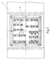
- a punching device 1 is illustrated in FIG. 1, with the help of which a predefined or selectable Hole patterns in flat structures, especially unfired ones Bring ceramic layers, so-called green sheets is how they are in the manufacture of ceramic substrates for electronic components or assemblies Find application.
- the punching device 1 includes a Table 2, which has a substantially flat top 3 and serves the green to be perforated Record sheet. Means for positioning the green Sheets on the table and for moving or moving the same are not further illustrated.
- a punching head 4 is arranged above the table 2 to which a base body 5 belongs, which is essentially flat is formed and with the table 2 a gap 6 Implementation and implementation of the green sheet defined.
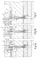
- the Basic body is by means not further illustrated in a predetermined position with respect to the table 2 positioned. If necessary, he can go to table 2 and be moved away from it so that the gap 6 narrows or opens. In operation, i.e. especially for However, the punching head 4 is used to carry out punching operations not moved. This is particularly from something less schematic representation according to Figure 2.
- the table 2, below which a receiving space 7 for Stamping waste and a corresponding discharge device are arranged, is overlapped by a frame 8, the has at its top an opening 9 into which the Immerse the punching head 4 with part of its base body 5 can.
- stamps 10, 11 and other stamps not illustrated For punching the inserted into the flat gap 6 Green sheets or other flat material, individual, on the punching head 4 provided stamps 10, 11 and other stamps not illustrated further moved in this way with their free end from the Step out of the base body 5, cross the gap 6 and in a corresponding opposite, in the table 2 enter the intended opening.
- the stamps 10, 11 are can be operated independently of one another.
- To the Drive is a drive unit 12, to the individual electric drive devices 13, 14 belong.
- each stamp 10, 11 is preferably its own, independent operable drive device assigned. In FIG. 2 is based on the stamp 11 and the drive device 14 symbolically illustrated.
- the drive device 14 is by one in detail magnetic drive or not further illustrated formed an electrodynamic drive that targeted can be controlled separately and when actuated one at its Bottom 15 protruding shaft 16 by a distance moved down.
- the drive device 14 is like the other drive devices, too, via corresponding Carrier elements 17 connected to the base body 5 and held so that the shaft 16 with the stamp 11 is aligned.
- the shaft 16 of the Stamp 11 serves a coupling device 18 to which, as shown in FIG 4 shows a coupling element 19 and one on the Stamp 11 provided head 20 belong.
- the head 20 of the Stamp 11 is formed by a cylindrical section, which has a larger diameter than one cylindrical directly adjoining the head 20 Shank section 21 of the stamp 11. This goes on its lower end in Figure 4 over a transition region 22 into a cylindrical stamping section 23.
- the shaft section 21 serves for the storage and guidance of the Stamp 11 on the base body 5. This has one to the punch 11 coaxial through bore 24, in a guide bushing 25 for the stamp 11 is arranged is.
- the guide bush 25 guides the shaft section 21 and thus the stamp 11 with little play and axially displaceable.
- the stamping section 23 projects into a through opening 26 of a guiding and stripping element 27, which on the Bottom of the base body 5 is seated in the bore 24.
- the stamp 11 is in a retracted position A if the punch section 23 does not come out of the opening 26 stands out.
- the stamp 10 or 11 then takes its advanced position B (punching position) on.
- That belonging to the coupling device 18 and of the coupling element 19 carried by the shaft 16 points to Inclusion of the on the shaft portion 21 of the stamp 11th molded or soldered on this cylindrical Head 20 has a receiving space 28 which is transverse to the Stamp 11, i.e. opens in a lateral direction X.
- the Recording space 28 is in relation to the longitudinal direction of the Stamp 11, which corresponds to its direction of movement Y, by two trained parallel to each other at a distance Surfaces, namely a flat surface 29 and one also flat bearing surface 30 limits its distance from each other is only slightly larger than the axial Length of the head 20. This sits with little play in the Recording room 28.
- the part of the coupling element which engages under the head 20 19, on which the contact surface 30 is formed, is forked or, in other words, with provided with an open edge 31 through which the Shaft section 21 of the stamp 11 extends.
- the open edge slot-like opening 31 is in the X direction Side open. However, their width is less than that Diameter of the head 20 so that this is not through the Opening 31 can slip.
- the coupling element 19 is, as also from Figure 4 emerges on its from the drive device 14 remote end with a serving as a positioning surface Inclined surface 32 provided in cooperation with an edge 33 formed on the base body 5 Positioning device for transferring the coupling element 19 has an upper position in which the Stamp 11 is in its retracted position A.
- the Edge 33 forms an abutment for the inclined surface 32.
- stamps 10, 11 are like all other stamps also, equally trained among themselves. Also agree those used to guide and store the stamp Guide bushings 25 and the guiding and stripping devices 27, and the coupling devices 18 and the Drive devices 13, 14 structurally completely with each other match, so the above description of the Stamp 11 and the parts cooperating with it Elements representative of the remaining stamps and the parts and elements interacting with them applies.
- the Stamps and drive devices can be grouped be arranged, as can be seen from Figure 3.
- the whole, drive unit formed by all drive devices 12 is mounted so that it is moved in the X direction can be so that all coupling elements 19th with the corresponding heads 20 of those assigned to them Stamps get in and out of engagement.
- a head plate 34 which is on a corresponding sliding surface 35 of the base body 5 in the X direction is slidably arranged.
- the head plate 34 On their top 36, the head plate 34 has a support surface area for each stamp 37 on that in a common plane with the contact surface 30 of each coupling element 19th If this is in an upper position, the retreat position A of the stamp 10, 11 defining position.
- the head plate 34 has 10, 11 for each stamp an opening 38 (opening) through which the respective Coupling element can pass through and to the Bearing area 37 borders.
- the bearing surface area 37 goes into an insertion slope about.
- a bulge 38a which is configured to the shaft portion 21 of the stamp 10, 11 record if the Head plate 34 under the respective head 20 of the stamp 10, 11 is pushed.
- the bulge 38a is open End of the opening 31 opposite and is practically in straight extension of the same arranged.
- the head plate 34 is displaceable in the X direction stored, the displacement is so large that the heads 20 of the punches 10, 11 from the coupling elements 19 are passed to the head plate 34 when the drive unit 12 together with the head plate 34 moved to uncouple the drive unit 12 in the X direction becomes.
- the head plate 34 is preferably with a Locking device connected, the moving only permitted together with the drive unit. At removed drive unit, the head plate is then locked.
- the thickness of the head plate 34 is preferably as large dimensioned as the thickness of the under each head 20th engaging part of the coupling element, i.e. the distance between the support surface 30 and that on the other Side of the relevant forked end face. This ensures that the bearing surface 30 and the bearing surface area 37 in a common plane lie when the drive unit 12 of the stamps 10, 11 by lateral displacement of the stamps 10, 11 is uncoupled.
- the coupling elements 19 arrive in attachment with one directly to the respective Edge 33 of the base body 5 adjoining the area Sliding surface 35, which is the position of the coupling elements 19th specifies.
- the heads 20 of all stamps are now from the Head plate 34 worn.
- the drive devices can be removed individually or in groups, whereby the Stamps are accessible. They can be used individually or in groups be replaced.
- all coupling elements 19 find the heads 20 in the correct position.
- the heads are straight and without height offset next to the respective recording room. Recoupling is possible without any problems, without the heads being subjected to 20 lateral forces.
- a punching device 1, in particular for punching of holes or hole patterns in green sheets, stamps 10, 11 on, the coupling elements 19 with drive devices 13, 14 are connected.
- the coupling elements are hook-shaped elements, the heads 20 of the Reach in under punch 10, 11 with a forked section.
- the coupling elements 19 is a head plate 34 assigned, which has openings 38 through which the Coupling elements 19 can dive.
- the head plate 34 is about level with the forked section the coupling elements 19 arranged when the stamp 10, 11 are in the retracted position.
- a side slot-like bulge 38a of the opening 38 is located between the fork fingers of the coupling element 19th trained slot opposite, so when uncoupling or coupling the drive devices from the plungers 10, 11 or to the plunger 10, 11, the heads 20 of the stamp 10, 11 in the retracted position A from the coupling elements 19 to the head plate 34 or from the head plate 34 to the Coupling elements 19 are passed.
Landscapes
- Engineering & Computer Science (AREA)
- Mechanical Engineering (AREA)
- Life Sciences & Earth Sciences (AREA)
- Forests & Forestry (AREA)
- Manufacturing & Machinery (AREA)
- Microelectronics & Electronic Packaging (AREA)
- Structural Engineering (AREA)
- Chemical & Material Sciences (AREA)
- Ceramic Engineering (AREA)
- Perforating, Stamping-Out Or Severing By Means Other Than Cutting (AREA)
- Vessels And Coating Films For Discharge Lamps (AREA)
- Punching Or Piercing (AREA)
Applications Claiming Priority (2)
| Application Number | Priority Date | Filing Date | Title |
|---|---|---|---|
| DE19855578A DE19855578C1 (de) | 1998-12-02 | 1998-12-02 | Stanzeinrichtung mit wechselbaren Stempeln |
| DE19855578 | 1998-12-02 |
Publications (3)
| Publication Number | Publication Date |
|---|---|
| EP1005963A2 true EP1005963A2 (fr) | 2000-06-07 |
| EP1005963A3 EP1005963A3 (fr) | 2002-08-14 |
| EP1005963B1 EP1005963B1 (fr) | 2005-04-13 |
Family
ID=7889728
Family Applications (1)
| Application Number | Title | Priority Date | Filing Date |
|---|---|---|---|
| EP99112221A Expired - Lifetime EP1005963B1 (fr) | 1998-12-02 | 1999-06-25 | Dispositif de poinçonnage ayant des poinçons remplaçables |
Country Status (6)
| Country | Link |
|---|---|
| US (2) | US6481323B1 (fr) |
| EP (1) | EP1005963B1 (fr) |
| JP (2) | JP2000173541A (fr) |
| AT (1) | ATE293032T1 (fr) |
| DE (2) | DE19855578C1 (fr) |
| ES (1) | ES2238792T3 (fr) |
Cited By (1)
| Publication number | Priority date | Publication date | Assignee | Title |
|---|---|---|---|---|
| EP1604751A1 (fr) * | 2004-06-09 | 2005-12-14 | Groz-Beckert KG | Dispositif de poinçonnage et poinçon |
Families Citing this family (15)
| Publication number | Priority date | Publication date | Assignee | Title |
|---|---|---|---|---|
| DE19855578C1 (de) * | 1998-12-02 | 2000-09-21 | Groz Beckert Kg | Stanzeinrichtung mit wechselbaren Stempeln |
| US6779426B1 (en) * | 1999-12-21 | 2004-08-24 | Atlas Die Llc | Die rule retention device and retaining board incorporating same |
| DE10246591A1 (de) * | 2002-10-05 | 2004-04-22 | Daimlerchrysler Ag | Stempelwerkzeug |
| DE10300831B4 (de) * | 2003-01-10 | 2006-10-26 | Groz-Beckert Kg | Stanzeinrichtung für Green Sheets |
| DE10311911B4 (de) * | 2003-03-17 | 2006-04-20 | Gs-Konstruktion Gmbh | Schnellwechselvorrichtung für Stanz,- Schneid- oder Lochstempel |
| DE102005060026B4 (de) * | 2005-12-14 | 2013-08-29 | Ms Spaichingen Gmbh | Vorrichtung zur Durchführung von Stanz- und/oder Schweiß- und/oder Klebearbeiten |
| EP1993335B1 (fr) * | 2007-05-14 | 2012-03-14 | Groz-Beckert KG | Dispositif de poinçonnage doté d'un tampon de changement et d'un modèle de poinçon variable |
| KR101071775B1 (ko) * | 2007-12-13 | 2011-10-11 | 기아자동차주식회사 | 판넬 가변트림라인 가공장치 |
| GB2459877A (en) * | 2008-05-08 | 2009-11-11 | Corridoor Ltd | Die for paperboard blanks, including selectively operable pins |
| DE202009010128U1 (de) | 2009-07-24 | 2009-10-08 | Josef Weischer Gmbh | Stanzvorrichtung |
| IT1400285B1 (it) * | 2010-06-04 | 2013-05-24 | Euromac Spa | Gruppo multi-utensile per presse punzonatrici |
| JP5552936B2 (ja) * | 2010-07-21 | 2014-07-16 | 岩崎電気株式会社 | 外球保護構造を備えたセラミックメタルハライドランプ |
| CN106363697B (zh) * | 2016-11-14 | 2018-01-12 | 杭州临安恒生科技股份有限公司 | Led灯罩自动冲料下料装置 |
| CN108312232A (zh) * | 2018-04-16 | 2018-07-24 | 厦门盈趣科技股份有限公司 | 一种冲切装置 |
| DE202019000468U1 (de) * | 2019-02-01 | 2019-02-22 | WISTA Werkzeugfertigungs-GmbH | Stanz-/Perforiermaschine |
Family Cites Families (19)
| Publication number | Priority date | Publication date | Assignee | Title |
|---|---|---|---|---|
| US629862A (en) * | 1899-05-20 | 1899-08-01 | William A Langjahr | Punching-machine. |
| US732279A (en) * | 1901-10-14 | 1903-06-30 | George Howlett Davis | Electrically-controlled perforating-machine. |
| US1257836A (en) * | 1917-01-25 | 1918-02-26 | Elizabeth F Boyle | Music-roll perforator. |
| US3051377A (en) * | 1958-07-11 | 1962-08-28 | Smith Corona Marchant Inc | Perforator |
| GB929412A (en) * | 1958-09-09 | 1963-06-19 | Svenska Dataregister Ab | Thrust transmitting device |
| US3452925A (en) * | 1967-05-31 | 1969-07-01 | Mosler Safe Co | Card punching and notching method and apparatus |
| US4235089A (en) * | 1979-05-29 | 1980-11-25 | Vecchi John C | Progressive stamping press |
| FR2519509A1 (fr) | 1981-12-31 | 1983-07-08 | Europ Composants Electron | Procede et dispositif pour la mise en boitier de composants electroniques |
| US4480782A (en) * | 1982-12-30 | 1984-11-06 | Toyota Jidosha Kabushiki Kaisha | Punch press die assembly with punch selecting mechanism |
| US4685613A (en) * | 1986-09-16 | 1987-08-11 | Frank Schambre | Reciprocable tool mounting module |
| JPH02124295A (ja) * | 1988-10-28 | 1990-05-11 | Ushio Kk | 多軸穿孔装置 |
| DE3915489C1 (fr) * | 1989-05-12 | 1990-05-23 | C. Behrens Ag, 3220 Alfeld, De | |
| US5024127A (en) * | 1989-10-10 | 1991-06-18 | International Business Machines Corporation | Punching mechanism |
| US5090284A (en) * | 1989-12-19 | 1992-02-25 | Hitachi Seiko, Ltd | Mechanisms for driving punch pins in punching apparatus |
| US5214991A (en) * | 1990-08-30 | 1993-06-01 | Hitachi, Ltd. | Punching apparatus |
| US5211095A (en) * | 1992-08-20 | 1993-05-18 | Murata Machinery, Limited | Arrangement enabling variably oriented punching with each tool in a multiple tool holder |
| US5233895A (en) * | 1992-11-12 | 1993-08-10 | International Business Machines Corp. | Magnetic plate punch actuator |
| US6223636B1 (en) * | 1998-08-03 | 2001-05-01 | International Business Machines Corporation | Low-cost high-density gang punch |
| DE19855578C1 (de) * | 1998-12-02 | 2000-09-21 | Groz Beckert Kg | Stanzeinrichtung mit wechselbaren Stempeln |
-
1998
- 1998-12-02 DE DE19855578A patent/DE19855578C1/de not_active Expired - Lifetime
-
1999
- 1999-06-25 ES ES99112221T patent/ES2238792T3/es not_active Expired - Lifetime
- 1999-06-25 EP EP99112221A patent/EP1005963B1/fr not_active Expired - Lifetime
- 1999-06-25 AT AT99112221T patent/ATE293032T1/de active
- 1999-06-25 DE DE59911899T patent/DE59911899D1/de not_active Expired - Lifetime
- 1999-11-30 US US09/450,700 patent/US6481323B1/en not_active Expired - Lifetime
- 1999-12-01 JP JP11342508A patent/JP2000173541A/ja active Pending
-
2000
- 2000-11-30 JP JP2000008502U patent/JP3078029U/ja not_active Expired - Lifetime
-
2002
- 2002-11-04 US US10/286,795 patent/US6619542B2/en not_active Expired - Lifetime
Cited By (2)
| Publication number | Priority date | Publication date | Assignee | Title |
|---|---|---|---|---|
| EP1604751A1 (fr) * | 2004-06-09 | 2005-12-14 | Groz-Beckert KG | Dispositif de poinçonnage et poinçon |
| US7578224B2 (en) | 2004-06-09 | 2009-08-25 | Groz-Beckert Kg | Punching device and punching die for it |
Also Published As
| Publication number | Publication date |
|---|---|
| EP1005963A3 (fr) | 2002-08-14 |
| JP3078029U (ja) | 2001-06-22 |
| US20030061927A1 (en) | 2003-04-03 |
| DE59911899D1 (de) | 2005-05-19 |
| US6481323B1 (en) | 2002-11-19 |
| ATE293032T1 (de) | 2005-04-15 |
| DE19855578C1 (de) | 2000-09-21 |
| US6619542B2 (en) | 2003-09-16 |
| JP2000173541A (ja) | 2000-06-23 |
| EP1005963B1 (fr) | 2005-04-13 |
| ES2238792T3 (es) | 2005-09-01 |
Similar Documents
| Publication | Publication Date | Title |
|---|---|---|
| EP1005963B1 (fr) | Dispositif de poinçonnage ayant des poinçons remplaçables | |
| DE69112688T2 (de) | Ausrichtvorrichtung zum Positionieren eines Steckergehäuses während des Drahteinführens. | |
| DE19520053B4 (de) | Bestückungsvorrichtung für Halbleiterelemente | |
| EP0272450B2 (fr) | Dispositif pour le test de plaquettes de circuit imprimé | |
| DE4128933A1 (de) | Stanzvorrichtung | |
| EP2694231B1 (fr) | Dispositif de transfert pour une presse ou un train de presses comprenant une transmission et support de base échangeable | |
| EP0287071B1 (fr) | Dispositif de changement d'outil pour machines à percer travaillant en coordonnées pour plaques à circuit imprimé | |
| EP1993335B1 (fr) | Dispositif de poinçonnage doté d'un tampon de changement et d'un modèle de poinçon variable | |
| DE3839892A1 (de) | Orientierungsvorrichtung fuer parallelepipedfoermige bauteile | |
| DE102019202939A1 (de) | Plattformeinheit, 3D-Druckvorrichtung und 3D-Druckverfahren | |
| EP0426798B1 (fr) | Dispositif de manipulation d'objets et son application | |
| EP2233626B1 (fr) | Aide à l'introduction destinée au garnissage de planches à pointes | |
| EP0331163A1 (fr) | Dispositif de contact pour dispositif de test pour tester des cartes imprimées ou similaires | |
| DE102008020368B4 (de) | Buchse für elektrisches Bauteil | |
| DE102006025361A1 (de) | Ausstoßeinheit zum Abtrennen von Bauelementen aus einer im Wesentlichen ebenen Anordnung von Bauelementen | |
| DE4209385C2 (de) | Preßmaschine für elektronische Komponenten des Chip-Types | |
| EP0054250A2 (fr) | Dispositif et méthode pour fixer une plaque en métal dur à la tête d'une tarière à spire | |
| DE4210650C2 (de) | Preßverfahren für elektronische Komponenten des Chip-Types | |
| DE19750643A1 (de) | Anschlußeinsetzmaschine mit verbessertem Schermechanismus | |
| DE2642040C3 (de) | Maschine zum automatischen Widerstandsschweißen von elektrische Kontakte bildenden Metallplättchen auf vorbestimmte Stellen eines Trägerbandes | |
| DE2625531A1 (de) | Vorrichtung zur herstellung von zusammengesetzten erzeugnissen | |
| WO2017194659A1 (fr) | Dispositif de placement hybride pour broches d'éjection et/ou griffes d'éjection | |
| DE69019707T2 (de) | Verfahren zum Befestigen von Laschen an den Enden elektrischer Drähte und in diesem Verfahren verwendeter Apparat. | |
| DE102021128728B3 (de) | Einpressmaschine zum Einpressen von Bauteilen in ein Substrat, insbesondere in eine Leiter- oder Trägerplatte, mit Wechseleinheit | |
| DE102019123099B3 (de) | Vorrichtung und Verfahren zum Herstellen von Schaltmodulen mit einem Gehäuse und zumindest einer darin eingeführten Elektronikkomponente |
Legal Events
| Date | Code | Title | Description |
|---|---|---|---|
| PUAI | Public reference made under article 153(3) epc to a published international application that has entered the european phase |
Free format text: ORIGINAL CODE: 0009012 |
|
| AK | Designated contracting states |
Kind code of ref document: A2 Designated state(s): AT BE CH CY DE DK ES FI FR GB GR IE IT LI LU MC NL PT SE |
|
| AX | Request for extension of the european patent |
Free format text: AL;LT;LV;MK;RO;SI |
|
| PUAL | Search report despatched |
Free format text: ORIGINAL CODE: 0009013 |
|
| AK | Designated contracting states |
Kind code of ref document: A3 Designated state(s): AT BE CH CY DE DK ES FI FR GB GR IE IT LI LU MC NL PT SE |
|
| AX | Request for extension of the european patent |
Free format text: AL;LT;LV;MK;RO;SI |
|
| RIC1 | Information provided on ipc code assigned before grant |
Free format text: 7B 26F 1/04 A, 7B 26F 1/02 B, 7B 23D 35/00 B, 7B 26D 7/26 B, 7H 05K 3/00 B |
|
| 17P | Request for examination filed |
Effective date: 20030117 |
|
| AKX | Designation fees paid |
Designated state(s): AT DE ES FR GB IT |
|
| 17Q | First examination report despatched |
Effective date: 20030728 |
|
| GRAP | Despatch of communication of intention to grant a patent |
Free format text: ORIGINAL CODE: EPIDOSNIGR1 |
|
| GRAS | Grant fee paid |
Free format text: ORIGINAL CODE: EPIDOSNIGR3 |
|
| GRAA | (expected) grant |
Free format text: ORIGINAL CODE: 0009210 |
|
| AK | Designated contracting states |
Kind code of ref document: B1 Designated state(s): AT DE ES FR GB IT |
|
| REG | Reference to a national code |
Ref country code: GB Ref legal event code: FG4D Free format text: NOT ENGLISH |
|
| GBT | Gb: translation of ep patent filed (gb section 77(6)(a)/1977) |
Effective date: 20050413 |
|
| REG | Reference to a national code |
Ref country code: IE Ref legal event code: FG4D Free format text: LANGUAGE OF EP DOCUMENT: GERMAN |
|
| REF | Corresponds to: |
Ref document number: 59911899 Country of ref document: DE Date of ref document: 20050519 Kind code of ref document: P |
|
| REG | Reference to a national code |
Ref country code: ES Ref legal event code: FG2A Ref document number: 2238792 Country of ref document: ES Kind code of ref document: T3 |
|
| ET | Fr: translation filed | ||
| PLBE | No opposition filed within time limit |
Free format text: ORIGINAL CODE: 0009261 |
|
| STAA | Information on the status of an ep patent application or granted ep patent |
Free format text: STATUS: NO OPPOSITION FILED WITHIN TIME LIMIT |
|
| 26N | No opposition filed |
Effective date: 20060116 |
|
| PGFP | Annual fee paid to national office [announced via postgrant information from national office to epo] |
Ref country code: GB Payment date: 20120622 Year of fee payment: 14 Ref country code: FR Payment date: 20120705 Year of fee payment: 14 |
|
| PGFP | Annual fee paid to national office [announced via postgrant information from national office to epo] |
Ref country code: IT Payment date: 20120627 Year of fee payment: 14 Ref country code: ES Payment date: 20120627 Year of fee payment: 14 |
|
| GBPC | Gb: european patent ceased through non-payment of renewal fee |
Effective date: 20130625 |
|
| REG | Reference to a national code |
Ref country code: FR Ref legal event code: ST Effective date: 20140228 |
|
| PG25 | Lapsed in a contracting state [announced via postgrant information from national office to epo] |
Ref country code: GB Free format text: LAPSE BECAUSE OF NON-PAYMENT OF DUE FEES Effective date: 20130625 |
|
| PG25 | Lapsed in a contracting state [announced via postgrant information from national office to epo] |
Ref country code: IT Free format text: LAPSE BECAUSE OF NON-PAYMENT OF DUE FEES Effective date: 20130625 Ref country code: FR Free format text: LAPSE BECAUSE OF NON-PAYMENT OF DUE FEES Effective date: 20130701 |
|
| REG | Reference to a national code |
Ref country code: ES Ref legal event code: FD2A Effective date: 20140707 |
|
| PG25 | Lapsed in a contracting state [announced via postgrant information from national office to epo] |
Ref country code: ES Free format text: LAPSE BECAUSE OF NON-PAYMENT OF DUE FEES Effective date: 20130626 |
|
| PGFP | Annual fee paid to national office [announced via postgrant information from national office to epo] |
Ref country code: DE Payment date: 20180630 Year of fee payment: 20 |
|
| PGFP | Annual fee paid to national office [announced via postgrant information from national office to epo] |
Ref country code: AT Payment date: 20180525 Year of fee payment: 20 |
|
| REG | Reference to a national code |
Ref country code: DE Ref legal event code: R071 Ref document number: 59911899 Country of ref document: DE |
|
| REG | Reference to a national code |
Ref country code: AT Ref legal event code: MK07 Ref document number: 293032 Country of ref document: AT Kind code of ref document: T Effective date: 20190625 |