EP1006008A1 - Bandage pneumatique radial - Google Patents
Bandage pneumatique radial Download PDFInfo
- Publication number
- EP1006008A1 EP1006008A1 EP99123248A EP99123248A EP1006008A1 EP 1006008 A1 EP1006008 A1 EP 1006008A1 EP 99123248 A EP99123248 A EP 99123248A EP 99123248 A EP99123248 A EP 99123248A EP 1006008 A1 EP1006008 A1 EP 1006008A1
- Authority
- EP
- European Patent Office
- Prior art keywords
- carcass
- fold back
- tire
- carcass plies
- plies
- Prior art date
- Legal status (The legal status is an assumption and is not a legal conclusion. Google has not performed a legal analysis and makes no representation as to the accuracy of the status listed.)
- Granted
Links
- 239000011324 bead Substances 0.000 claims abstract description 21
- 230000002787 reinforcement Effects 0.000 claims description 10
- 239000000945 filler Substances 0.000 description 4
- 239000000835 fiber Substances 0.000 description 3
- 238000010030 laminating Methods 0.000 description 3
- 238000004519 manufacturing process Methods 0.000 description 3
- 229910000831 Steel Inorganic materials 0.000 description 2
- 238000011156 evaluation Methods 0.000 description 2
- 230000002093 peripheral effect Effects 0.000 description 2
- 230000001737 promoting effect Effects 0.000 description 2
- 239000010959 steel Substances 0.000 description 2
- 239000004677 Nylon Substances 0.000 description 1
- 229920002302 Nylon 6,6 Polymers 0.000 description 1
- 229920000297 Rayon Polymers 0.000 description 1
- 229920006231 aramid fiber Polymers 0.000 description 1
- 238000006243 chemical reaction Methods 0.000 description 1
- 238000007796 conventional method Methods 0.000 description 1
- 238000006073 displacement reaction Methods 0.000 description 1
- 239000000463 material Substances 0.000 description 1
- 229920001778 nylon Polymers 0.000 description 1
- 229920000728 polyester Polymers 0.000 description 1
- 239000002964 rayon Substances 0.000 description 1
Images


Classifications
-
- B—PERFORMING OPERATIONS; TRANSPORTING
- B60—VEHICLES IN GENERAL
- B60C—VEHICLE TYRES; TYRE INFLATION; TYRE CHANGING; CONNECTING VALVES TO INFLATABLE ELASTIC BODIES IN GENERAL; DEVICES OR ARRANGEMENTS RELATED TO TYRES
- B60C15/00—Tyre beads, e.g. ply turn-up or overlap
- B60C15/0009—Tyre beads, e.g. ply turn-up or overlap features of the carcass terminal portion
- B60C15/0036—Tyre beads, e.g. ply turn-up or overlap features of the carcass terminal portion with high ply turn-up, i.e. folded around the bead core and terminating radially above the point of maximum section width
- B60C15/0045—Tyre beads, e.g. ply turn-up or overlap features of the carcass terminal portion with high ply turn-up, i.e. folded around the bead core and terminating radially above the point of maximum section width with ply turn-up up to the belt edges, i.e. folded around the bead core and extending to the belt edges
-
- B—PERFORMING OPERATIONS; TRANSPORTING
- B60—VEHICLES IN GENERAL
- B60C—VEHICLE TYRES; TYRE INFLATION; TYRE CHANGING; CONNECTING VALVES TO INFLATABLE ELASTIC BODIES IN GENERAL; DEVICES OR ARRANGEMENTS RELATED TO TYRES
- B60C15/00—Tyre beads, e.g. ply turn-up or overlap
- B60C15/0009—Tyre beads, e.g. ply turn-up or overlap features of the carcass terminal portion
- B60C15/0036—Tyre beads, e.g. ply turn-up or overlap features of the carcass terminal portion with high ply turn-up, i.e. folded around the bead core and terminating radially above the point of maximum section width
-
- B—PERFORMING OPERATIONS; TRANSPORTING
- B60—VEHICLES IN GENERAL
- B60C—VEHICLE TYRES; TYRE INFLATION; TYRE CHANGING; CONNECTING VALVES TO INFLATABLE ELASTIC BODIES IN GENERAL; DEVICES OR ARRANGEMENTS RELATED TO TYRES
- B60C15/00—Tyre beads, e.g. ply turn-up or overlap
- B60C15/06—Flipper strips, fillers, or chafing strips and reinforcing layers for the construction of the bead
-
- B—PERFORMING OPERATIONS; TRANSPORTING
- B60—VEHICLES IN GENERAL
- B60C—VEHICLE TYRES; TYRE INFLATION; TYRE CHANGING; CONNECTING VALVES TO INFLATABLE ELASTIC BODIES IN GENERAL; DEVICES OR ARRANGEMENTS RELATED TO TYRES
- B60C9/00—Reinforcements or ply arrangement of pneumatic tyres
- B60C9/02—Carcasses
- B60C9/04—Carcasses the reinforcing cords of each carcass ply arranged in a substantially parallel relationship
- B60C9/08—Carcasses the reinforcing cords of each carcass ply arranged in a substantially parallel relationship the cords extend transversely from bead to bead, i.e. radial ply
-
- Y—GENERAL TAGGING OF NEW TECHNOLOGICAL DEVELOPMENTS; GENERAL TAGGING OF CROSS-SECTIONAL TECHNOLOGIES SPANNING OVER SEVERAL SECTIONS OF THE IPC; TECHNICAL SUBJECTS COVERED BY FORMER USPC CROSS-REFERENCE ART COLLECTIONS [XRACs] AND DIGESTS
- Y10—TECHNICAL SUBJECTS COVERED BY FORMER USPC
- Y10T—TECHNICAL SUBJECTS COVERED BY FORMER US CLASSIFICATION
- Y10T152/00—Resilient tires and wheels
- Y10T152/10—Tires, resilient
- Y10T152/10495—Pneumatic tire or inner tube
- Y10T152/10819—Characterized by the structure of the bead portion of the tire
- Y10T152/10828—Chafer or sealing strips
Definitions
- the present invention relates to a pneumatic radial tire in which a carcass ply (carcass layer) is constructed by a semiradial structure, particularly to a pneumatic radial tire promoting driving stability without being accompanied by an increase in mass or a reduction in productivity.
- a tire in which a carcass cord of a carcass ply is arranged by less than 90 degree relative to a tire equator is particularly referred to as a semi-radial tire.
- a conventional semi-radial tire for a passenger vehicle as shown by Fig. 3A, two sheets of carcass plies 21 and 22 in which carcass cords are intersected with each other between the plies, are arranged to reach bead portions 25 from a tread portion 23 via left and right side portions 24 and both end portions thereof are folded back to wrap bead fillers 27 from the inner side to the outer side of the tire respectively around left and right bead cores 26.
- the tread portion 23 is arranged with two sheets of belt layers 28 over the entire periphery of the tire along the peripheral direction of the tire on the outer side of the outer side carcass ply 21.
- a fold back portion 21b of the carcass ply 21 constituting the outermost side on an inner side of the bead core 26 in the bead portion 25, is extended to the side of the tread portion 23 along an unfolded portion 21a of the carcass ply 21 (that is, main body portion).
- a fold back portion 22b of the carcass ply 22 rides over a distal end 21e of the fold back portion 21b to cover a total of the fold back portion 21b and is successively extended to the side of the tread portion 23 along the main body portion 21a. Therefore, a distal end 22e of the fold back portion 22b is disposed on the side of the tread portion 23 relative to the distal end 21e of the fold back portion 21b.
- a reinforcement layer comprising steel cords or fiber cords are arranged on the outer side of the bead filler 27.
- a reinforcement layer comprising steel cords or fiber cords are arranged on the outer side of the bead filler 27.
- such an additional arrangement of the reinforcement layer gives rise to an increase in a mass of the tire by that amount, increases also tire fabrication steps and is obliged to submit to disadvantage resulting in a reduction in the productivity.
- a pneumatic radial tire comprising a plurality of sheets of carcass plies in which carcass cords of the carcass plies are inclined to a tire equator by an angle equal to or more than 65 degree and less than 90 degree and are intersected with each other between, the plies both end portions of the carcass plies being mounted to fold back from an inner side to an outer side of the tire respectively around left and right bead cores and wherein a fold back portion of the carcass ply constituting an outermost side on an inner side of the bead core in the plurality of sheets of carcass plies is laminated on an unfolded portion of the carcass ply, the carcass cords of the carcass plies are intersected with each other between laminated layers thereof and a length of the fold back portion is made longer than any of the fold back portions of all of the remaining carcass plies.
- the length of the fold back portion of the carcass ply constituting the outermost side on the inner side of the bead core and extended from the main body portion is made longer than any of fold back portions of all of the remaining carcass plies and therefore, a laminated layer region in which carcass cords intersect with each other between laminated layers of the main body portion and the fold back portion can be made wider than that of the conventional tire of Fig. 3A and Fig. 3B.
- the laminated layer region in which the carcass cords intersect with each other in this way is provided with the flexural rigidity larger than that of the laminated layer region in which the carcass cords are brought into a state in which the carcass cords are in parallel with each other between the layers and therefore, according to the invention, compared with the conventional tire of Fig. 3A and Fig. 3B, the lateral rigidity of the side of the tire can be increased and the driving stability can be promoted.
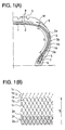
- a tire of the invention as shown by Fig. 1A, two sheets of carcass plies 1 and 2 in which carcass cords are laminated to intersect with each other between the plies, are arranged to reach bead portions 5 from a tread portion 3 via left and right side portions 4 and both end portions thereof are folded back to wrap bead fillers 7 from the inner side to the outer side of the tire respectively around left and right bead cores 6.
- the respective carcass cords of the carcass plies 1 and 2 are inclined by an angle of less than 90 degree relative to the tire equator.
- the tread portion 3 is arranged with two sheets of belt layers 8 over the entire periphery of the tire along the peripheral direction of the tire on the outer side of the outer side carcass ply 1.
- a fold back portion 1b of the carcass ply 1 constituting the outermost side on an inner side of the bead core 6 in the bead portion 5, is extended to an inner side of a wing tip 9 at a vicinity of an end portion of the shoulder along a main body portion 1a of the carcass ply 1 and is directly laminated on the main body portion 1a.
- a fold back portion 2b of the carcass ply 2 is extended to the side of the tread portion 3 along the fold back portion 1b and by directly laminating on the fold back portion 1b.
- a length of the fold back portion 1b is longer than a length of the fold back portion 2b. That is, a distal end 1e of the fold back portion 1b is disposed on the side of the tread portion 23 relative to a distal end 2e of the fold back portion 2b.
- Notation 2a designates a main body portion of the carcass ply 2.
- the fold back portion 1b and the main body portion 1a are laminated to each other such that a carcass cord 1c of the fold back portion 1b and the carcass cord 1c of the main body portion 1a intersect with each other in a region S excluding a portion where the bead filler 7 is interposed.
- S of Fig. 1A is equal to S'+S'' of Fig. 3A and S>S' in the regions S and S' in which the carcass cords intersect with each other between the layers and therefore, the flexural rigidity of the side portion of the tire of Fig. 1A is larger than that of the tire of Fig. 3A, further, the driving stability is more excellent.
- materials of the both tires are quite the same, the fabrication steps also stays the same and therefore, the tire mass and the productivity stay quite the same.
- Fig. 2 is a semi-sectional view of a semi-radial tire in the meridian direction showing other embodiment of the invention.
- the semi-radial tire is constructed by a constitution similar to that in the above-described embodiment except that an reinforcement layer 11 is arranged on the outer side of the fold back portions 1b and 2b of the carcass plies 1 and 2.
- the reinforcement layer 11 comprises reinforcement cords of steel cords or organic fiber cords and the reinforcement cords intersect with the carcass cord 2c of the fold back portion 2b on the outermost side. According to such a tire, the rigidity of the bead portion 5 can further be increased.
- cords comprising organic fiber of nylon, polyester, aramid fiber or rayon.
- any of angle ranges which have conventionally been used in semi-radial tires are applicable and the angle ranges are preferably equal to or more than 65 degree and less than 90 degree relative to the tire equator, more preferably equal to or more than 65 degree and less than 87 degree.
- a number of implanting the carcass cords may also fall in a range which has been applied to the conventional semi-radial tire and the number is preferably 45 pieces through 55 pieces / 50 mm at the tire equator.
- the length of the fold back portion of the carcass ply is not particularly restricted, when the distal end is arranged to the tread side rather than a maximum width portion of the tire, the feature of the present invention can fully be utilized and it is preferable that the distal end of the fold back portion of the carcass ply laminated on the outermost side is extended to a vicinity of an edge portion of the tread shoulder, particularly to an inner side of the wing chip.
- the carcass plies can be laminated up to a maximum of four sheets.
- a tire according to the invention and the conventional tire constructed by a common constitution in which the tire size is 225/45R17 and two layers of carcass plies are arranged such that nylon 66 cords of 1260d/2 are inclined by 70 degree relative to the tire equator and a number of ends thereof at the tire equator is 50 pieces / 50 mm and by a constitution in which arrangement of distal ends of two fold back portions differ from each other as respectively shown by Figs. 1A and 1B and Figs. 3A and 3B.
- S 50 mm
- S' 30 mm
- S'' 20 mm.
- the respective tires are filled with air under an internal pressure of 200kPa and a total of the outer periphery of the tread portion is brought into a fixed state, a displacement in an axial direction of tire is applied from the rim and the reaction force is measured as the lateral rigidity of the side.
- An evaluation is carried out by inverse numbers and is designated by indices with an inverse number of a measured value of the conventional tire as 100. The larger the index value, the more excellent is the lateral rigidity of the side. The result is shown in Table 1.
- the fold back portion of the carcass ply constituting the outermost side on an inner side of the bead core is laminated to the unfolded portion of the carcass ply (that is, main body portion)
- the carcass cords of the carcass plies intersect with each other between the laminated layers and the length of the fold back portion is made longer than any of the fold back portions of the total carcass plies and accordingly, while making the mass and the productivity of the invented tire at the same levels as those of the conventional pneumatic radial tire, the region of laminating the carcass cords to intersect with each other between the layers can be maximized and accordingly, the side lateral rigidity can be increased as large as possible and the driving stability can be promoted.
Landscapes
- Engineering & Computer Science (AREA)
- Mechanical Engineering (AREA)
- Tires In General (AREA)
Applications Claiming Priority (2)
| Application Number | Priority Date | Filing Date | Title |
|---|---|---|---|
| JP34022398 | 1998-11-30 | ||
| JP34022398A JP3868132B2 (ja) | 1998-11-30 | 1998-11-30 | 空気入りラジアルタイヤ |
Publications (2)
| Publication Number | Publication Date |
|---|---|
| EP1006008A1 true EP1006008A1 (fr) | 2000-06-07 |
| EP1006008B1 EP1006008B1 (fr) | 2005-01-26 |
Family
ID=18334885
Family Applications (1)
| Application Number | Title | Priority Date | Filing Date |
|---|---|---|---|
| EP99123248A Expired - Lifetime EP1006008B1 (fr) | 1998-11-30 | 1999-11-29 | Bandage pneumatique radial |
Country Status (4)
| Country | Link |
|---|---|
| US (1) | US6296031B1 (fr) |
| EP (1) | EP1006008B1 (fr) |
| JP (1) | JP3868132B2 (fr) |
| DE (1) | DE69923415T2 (fr) |
Cited By (1)
| Publication number | Priority date | Publication date | Assignee | Title |
|---|---|---|---|---|
| CN109955654A (zh) * | 2017-12-26 | 2019-07-02 | 东洋橡胶工业株式会社 | 充气轮胎 |
Families Citing this family (3)
| Publication number | Priority date | Publication date | Assignee | Title |
|---|---|---|---|---|
| US7320350B2 (en) * | 2005-07-08 | 2008-01-22 | Bridgestone Firestone North American Tire, Llc | Sidewall reinforcing layer for pneumatic tires |
| JP7132098B2 (ja) | 2018-11-14 | 2022-09-06 | 株式会社ブリヂストン | タイヤ |
| JP2025022579A (ja) * | 2023-08-03 | 2025-02-14 | 株式会社ブリヂストン | タイヤの製造方法 |
Citations (8)
| Publication number | Priority date | Publication date | Assignee | Title |
|---|---|---|---|---|
| FR1413598A (fr) * | 1963-11-14 | 1965-10-08 | Goodyear Tire & Rubber | Procédé de traitement des extrémités des câblés dans un pneumatique |
| GB2096951A (en) * | 1981-04-17 | 1982-10-27 | Goodyear Tire & Rubber | Motorcycle tire |
| EP0196266A2 (fr) * | 1985-03-25 | 1986-10-01 | The Goodyear Tire & Rubber Company | Bandage pneumatique |
| JPS62205804A (ja) * | 1986-03-05 | 1987-09-10 | Bridgestone Corp | 重荷重用空気入りバイアスタイヤ |
| EP0484831A1 (fr) * | 1990-11-03 | 1992-05-13 | Continental Aktiengesellschaft | Bandage pneumatique pour bicyclette |
| US5117888A (en) * | 1988-05-30 | 1992-06-02 | The Ohtsu Tire & Rubber Co. Ltd. | Radial tire with reinforcing layer in bead region |
| EP0631889A1 (fr) * | 1993-06-29 | 1995-01-04 | The Goodyear Tire & Rubber Company | Construction de serrage verrouillée, se terminant en hauteur |
| EP0819553A2 (fr) * | 1996-07-17 | 1998-01-21 | Sumitomo Rubber Industries Ltd. | Bandage pneumatique |
Family Cites Families (6)
| Publication number | Priority date | Publication date | Assignee | Title |
|---|---|---|---|---|
| US3244215A (en) * | 1963-11-14 | 1966-04-05 | Goodyear Tire & Rubber | Tire cord endings |
| US4854362A (en) * | 1988-05-23 | 1989-08-08 | The Goodyear Tire & Rubber Company | Pneumatic tire |
| JPH07246807A (ja) * | 1994-03-08 | 1995-09-26 | Sumitomo Rubber Ind Ltd | 空気入りラジアルタイヤ |
| JPH07290911A (ja) * | 1994-04-27 | 1995-11-07 | Ohtsu Tire & Rubber Co Ltd :The | ラリー用空気入りラジアルタイヤ |
| JP3667810B2 (ja) * | 1995-02-28 | 2005-07-06 | 住友ゴム工業株式会社 | 空気入りラジアルタイヤ |
| JPH08324213A (ja) * | 1995-05-30 | 1996-12-10 | Yokohama Rubber Co Ltd:The | 空気入りラジアルタイヤ |
-
1998
- 1998-11-30 JP JP34022398A patent/JP3868132B2/ja not_active Expired - Fee Related
-
1999
- 1999-11-24 US US09/448,138 patent/US6296031B1/en not_active Expired - Lifetime
- 1999-11-29 EP EP99123248A patent/EP1006008B1/fr not_active Expired - Lifetime
- 1999-11-29 DE DE69923415T patent/DE69923415T2/de not_active Expired - Lifetime
Patent Citations (8)
| Publication number | Priority date | Publication date | Assignee | Title |
|---|---|---|---|---|
| FR1413598A (fr) * | 1963-11-14 | 1965-10-08 | Goodyear Tire & Rubber | Procédé de traitement des extrémités des câblés dans un pneumatique |
| GB2096951A (en) * | 1981-04-17 | 1982-10-27 | Goodyear Tire & Rubber | Motorcycle tire |
| EP0196266A2 (fr) * | 1985-03-25 | 1986-10-01 | The Goodyear Tire & Rubber Company | Bandage pneumatique |
| JPS62205804A (ja) * | 1986-03-05 | 1987-09-10 | Bridgestone Corp | 重荷重用空気入りバイアスタイヤ |
| US5117888A (en) * | 1988-05-30 | 1992-06-02 | The Ohtsu Tire & Rubber Co. Ltd. | Radial tire with reinforcing layer in bead region |
| EP0484831A1 (fr) * | 1990-11-03 | 1992-05-13 | Continental Aktiengesellschaft | Bandage pneumatique pour bicyclette |
| EP0631889A1 (fr) * | 1993-06-29 | 1995-01-04 | The Goodyear Tire & Rubber Company | Construction de serrage verrouillée, se terminant en hauteur |
| EP0819553A2 (fr) * | 1996-07-17 | 1998-01-21 | Sumitomo Rubber Industries Ltd. | Bandage pneumatique |
Non-Patent Citations (1)
| Title |
|---|
| PATENT ABSTRACTS OF JAPAN vol. 012, no. 057 (M - 670) 20 February 1988 (1988-02-20) * |
Cited By (2)
| Publication number | Priority date | Publication date | Assignee | Title |
|---|---|---|---|---|
| CN109955654A (zh) * | 2017-12-26 | 2019-07-02 | 东洋橡胶工业株式会社 | 充气轮胎 |
| CN109955654B (zh) * | 2017-12-26 | 2020-09-22 | 东洋橡胶工业株式会社 | 充气轮胎 |
Also Published As
| Publication number | Publication date |
|---|---|
| US6296031B1 (en) | 2001-10-02 |
| DE69923415D1 (de) | 2005-03-03 |
| EP1006008B1 (fr) | 2005-01-26 |
| JP2000158918A (ja) | 2000-06-13 |
| DE69923415T2 (de) | 2005-12-22 |
| JP3868132B2 (ja) | 2007-01-17 |
Similar Documents
| Publication | Publication Date | Title |
|---|---|---|
| EP1203672B1 (fr) | Bandage pneumatique | |
| US5441093A (en) | Motorcycle radial tire with folded breaker ply and spirally wound band ply | |
| EP1342592B1 (fr) | Bandage pneumatique pour moto | |
| US7128114B2 (en) | Pneumatic tire and method of manufacturing the tire | |
| JP3702911B2 (ja) | 空気入りラジアルタイヤ | |
| JPH01309805A (ja) | 空気入りタイヤ | |
| EP0850788A1 (fr) | Bandage pneumatique radial | |
| JP3540966B2 (ja) | 空気入りラジアルタイヤ | |
| JP2002144814A (ja) | 空気入りラジアルタイヤ | |
| CN109070641B (zh) | 充气轮胎 | |
| JP4420504B2 (ja) | 空気入りタイヤ | |
| EP0565339A1 (fr) | Bandage pneumatique pour moto | |
| EP1006008B1 (fr) | Bandage pneumatique radial | |
| JP4132275B2 (ja) | 空気入りラジアルタイヤ | |
| JPH05238208A (ja) | 空気入りタイヤ | |
| JP3837219B2 (ja) | 空気入りラジアルタイヤ | |
| JP3868133B2 (ja) | 空気入りラジアルタイヤ | |
| JP2007161027A (ja) | 空気入りタイヤ | |
| JP3124851B2 (ja) | 重荷重用タイヤ | |
| EP1488939A1 (fr) | Pneumatique | |
| JP2001191744A (ja) | 空気入りラジアルタイヤ | |
| JP2768425B2 (ja) | 空気入りタイヤ | |
| JPH10109503A (ja) | 空気入りラジアルタイヤ | |
| JP7669750B2 (ja) | 空気入りタイヤ | |
| JPH07290912A (ja) | 空気入りタイヤ |
Legal Events
| Date | Code | Title | Description |
|---|---|---|---|
| PUAI | Public reference made under article 153(3) epc to a published international application that has entered the european phase |
Free format text: ORIGINAL CODE: 0009012 |
|
| AK | Designated contracting states |
Kind code of ref document: A1 Designated state(s): DE FR GB IT |
|
| AX | Request for extension of the european patent |
Free format text: AL;LT;LV;MK;RO;SI |
|
| 17P | Request for examination filed |
Effective date: 20000829 |
|
| AKX | Designation fees paid |
Free format text: DE FR GB IT |
|
| 17Q | First examination report despatched |
Effective date: 20020917 |
|
| GRAP | Despatch of communication of intention to grant a patent |
Free format text: ORIGINAL CODE: EPIDOSNIGR1 |
|
| GRAS | Grant fee paid |
Free format text: ORIGINAL CODE: EPIDOSNIGR3 |
|
| GRAA | (expected) grant |
Free format text: ORIGINAL CODE: 0009210 |
|
| AK | Designated contracting states |
Kind code of ref document: B1 Designated state(s): DE FR GB IT |
|
| REG | Reference to a national code |
Ref country code: GB Ref legal event code: FG4D |
|
| REF | Corresponds to: |
Ref document number: 69923415 Country of ref document: DE Date of ref document: 20050303 Kind code of ref document: P |
|
| PLBE | No opposition filed within time limit |
Free format text: ORIGINAL CODE: 0009261 |
|
| STAA | Information on the status of an ep patent application or granted ep patent |
Free format text: STATUS: NO OPPOSITION FILED WITHIN TIME LIMIT |
|
| ET | Fr: translation filed | ||
| 26N | No opposition filed |
Effective date: 20051027 |
|
| REG | Reference to a national code |
Ref country code: FR Ref legal event code: PLFP Year of fee payment: 17 |
|
| REG | Reference to a national code |
Ref country code: FR Ref legal event code: PLFP Year of fee payment: 18 |
|
| REG | Reference to a national code |
Ref country code: FR Ref legal event code: PLFP Year of fee payment: 19 |
|
| REG | Reference to a national code |
Ref country code: FR Ref legal event code: PLFP Year of fee payment: 20 |
|
| PGFP | Annual fee paid to national office [announced via postgrant information from national office to epo] |
Ref country code: DE Payment date: 20181113 Year of fee payment: 20 |
|
| PGFP | Annual fee paid to national office [announced via postgrant information from national office to epo] |
Ref country code: GB Payment date: 20181128 Year of fee payment: 20 Ref country code: FR Payment date: 20181011 Year of fee payment: 20 Ref country code: IT Payment date: 20181122 Year of fee payment: 20 |
|
| REG | Reference to a national code |
Ref country code: DE Ref legal event code: R071 Ref document number: 69923415 Country of ref document: DE |
|
| REG | Reference to a national code |
Ref country code: GB Ref legal event code: PE20 Expiry date: 20191128 |
|
| PG25 | Lapsed in a contracting state [announced via postgrant information from national office to epo] |
Ref country code: GB Free format text: LAPSE BECAUSE OF EXPIRATION OF PROTECTION Effective date: 20191128 |