EP1006032A2 - Vehicle wheel unit - Google Patents
Vehicle wheel unit Download PDFInfo
- Publication number
- EP1006032A2 EP1006032A2 EP99118947A EP99118947A EP1006032A2 EP 1006032 A2 EP1006032 A2 EP 1006032A2 EP 99118947 A EP99118947 A EP 99118947A EP 99118947 A EP99118947 A EP 99118947A EP 1006032 A2 EP1006032 A2 EP 1006032A2
- Authority
- EP
- European Patent Office
- Prior art keywords
- wheel
- signal
- module
- vehicle
- control
- Prior art date
- Legal status (The legal status is an assumption and is not a legal conclusion. Google has not performed a legal analysis and makes no representation as to the accuracy of the status listed.)
- Granted
Links
- 238000004364 calculation method Methods 0.000 claims description 10
- 230000006870 function Effects 0.000 claims description 8
- 230000001133 acceleration Effects 0.000 claims description 4
- 230000009467 reduction Effects 0.000 claims description 2
- 238000000034 method Methods 0.000 description 8
- 238000011161 development Methods 0.000 description 5
- 230000008901 benefit Effects 0.000 description 4
- 230000005540 biological transmission Effects 0.000 description 4
- 238000011156 evaluation Methods 0.000 description 3
- 238000012545 processing Methods 0.000 description 3
- 238000012546 transfer Methods 0.000 description 3
- 230000001419 dependent effect Effects 0.000 description 2
- 238000005315 distribution function Methods 0.000 description 2
- 230000000903 blocking effect Effects 0.000 description 1
- 230000001934 delay Effects 0.000 description 1
- 230000006872 improvement Effects 0.000 description 1
- 238000009434 installation Methods 0.000 description 1
- 230000008569 process Effects 0.000 description 1
- 230000001737 promoting effect Effects 0.000 description 1
- 230000002123 temporal effect Effects 0.000 description 1
- 238000012549 training Methods 0.000 description 1
- 230000003313 weakening effect Effects 0.000 description 1
Images


Classifications
-
- B—PERFORMING OPERATIONS; TRANSPORTING
- B60—VEHICLES IN GENERAL
- B60T—VEHICLE BRAKE CONTROL SYSTEMS OR PARTS THEREOF; BRAKE CONTROL SYSTEMS OR PARTS THEREOF, IN GENERAL; ARRANGEMENT OF BRAKING ELEMENTS ON VEHICLES IN GENERAL; PORTABLE DEVICES FOR PREVENTING UNWANTED MOVEMENT OF VEHICLES; VEHICLE MODIFICATIONS TO FACILITATE COOLING OF BRAKES
- B60T13/00—Transmitting braking action from initiating means to ultimate brake actuator with power assistance or drive; Brake systems incorporating such transmitting means, e.g. air-pressure brake systems
- B60T13/10—Transmitting braking action from initiating means to ultimate brake actuator with power assistance or drive; Brake systems incorporating such transmitting means, e.g. air-pressure brake systems with fluid assistance, drive, or release
- B60T13/66—Electrical control in fluid-pressure brake systems
- B60T13/662—Electrical control in fluid-pressure brake systems characterised by specified functions of the control system components
-
- B—PERFORMING OPERATIONS; TRANSPORTING
- B60—VEHICLES IN GENERAL
- B60T—VEHICLE BRAKE CONTROL SYSTEMS OR PARTS THEREOF; BRAKE CONTROL SYSTEMS OR PARTS THEREOF, IN GENERAL; ARRANGEMENT OF BRAKING ELEMENTS ON VEHICLES IN GENERAL; PORTABLE DEVICES FOR PREVENTING UNWANTED MOVEMENT OF VEHICLES; VEHICLE MODIFICATIONS TO FACILITATE COOLING OF BRAKES
- B60T8/00—Arrangements for adjusting wheel-braking force to meet varying vehicular or ground-surface conditions, e.g. limiting or varying distribution of braking force
- B60T8/32—Arrangements for adjusting wheel-braking force to meet varying vehicular or ground-surface conditions, e.g. limiting or varying distribution of braking force responsive to a speed condition, e.g. acceleration or deceleration
- B60T8/321—Arrangements for adjusting wheel-braking force to meet varying vehicular or ground-surface conditions, e.g. limiting or varying distribution of braking force responsive to a speed condition, e.g. acceleration or deceleration deceleration
Definitions
- the invention relates to a wheel module for a vehicle with an electrically controllable braking system (EBS) Control of the braking force on at least one wheel of the Vehicle according to the preamble of claim 1.
- EBS electrically controllable braking system
- Such a wheel module is known from EP 0 467 112 B1.
- the known wheel module is part of an electrically controllable Braking system, which wheel modules, central modules and donor facilities such.
- B. a brake value transmitter having.
- the known wheel module is a wheel one Assigned to the vehicle.
- Using the same bike assigned rotational speed sensor is a Signal representing the rotational speed of the wheel generated and the wheel module assigned to this wheel Evaluation fed.
- One arranged in the wheel module electronic control device with a microprocessor evaluates this signal and sends a calculated one Speed signal via a data bus system out.
- Several wheel modules are connected via the data bus system, which each send out a speed signal, connected to a central module.
- the central module evaluates the speed signals received by the data bus system and calculates z.
- B. a vehicle reference speed, for an anti-lock control is required. This vehicle reference speed and if necessary, further, for an anti-lock control sends required calculation results the central module then back to the wheel modules, which this data then for an anti-lock control use on the wheel assigned to them.
- the invention is therefore based on the object Specify wheel module and a braking system in which the Data transmission effort is reduced.
- the invention has the advantage that the effort for Data transmission between the modules of the braking system is reduced to an extremely low level by the for brake control with anti-lock control necessary calculation results calculated from the input signals, such as B. a vehicle reference speed, Slip signals, acceleration signals, Brake force reduction, stop and / or reconstruction signals, not in a central location, d. H. in a central module, calculated and via the data bus system to the Wheel modules is transmitted, but directly in a wheel module is calculated locally. Because in particular an anti-lock control is also very time critical an improvement in the control quality can be achieved because of time delays, which result from a data transfer between the central module and the wheel module avoided become.
- Wheel module is that it is also without a central module or even if the central module fails Limitations regarding the anti-lock control procedure operate. So even without a central module e.g. B. a so-called modified individual regulation, such as. known from DE 28 51 107 C2, on a steerable axis to mitigate changes in yaw moment be carried out. Even more, the specialist common control principles, e.g. variable Axis control or modified axis control can both with and without a central module become.
- Another advantage of the invention is that the same control program is provided in each wheel module can be so that regardless of the number of used Only one wheel module in a vehicle Control program is to be created, reducing the development effort is relatively small.
- the invention becomes a definition of the wheel assignment of a wheel module by entering a wheel position parameter that is in a electronic control device provided in the wheel module is entered.
- This has the Advantage that initially identical wheel modules are manufactured can be, which only at a relatively late Time, e.g. B. when installed in a vehicle, get their function assigned in detail.
- a Wheel assignment is necessary, for example, in order to steerable axle of a vehicle the anti-lock control according to another principle, e.g. B. as already mentioned Modified individual regulation to be carried out than on a non-steerable axle of the vehicle for example a so-called individual regulation is carried out.
- Entering the wheel position parameter can e.g. B. manually by operating a diagnostic device that the Corresponding data transmitted to wheel modules become. If a central module is provided in the brake system is then takes according to an advantageous development of the invention the central module the assignment the wheel assignment automatically before, for. B. once at First installation of the brake system. Then in the central module information about the wheel allocation and saved the braking system.
- the invention does not transmit all wheel modules their respective speed signal, but only those wheel modules whose speed signals are required in other wheel modules. This will the effort for data transmission was kept low.
- the electronic control device can advantageously of a wheel module based on the wheel position parameter detect whether the speed signal is above the data bus system is to be transmitted or not.
- a braking system with several wheel modules from the previous one described type and to be equipped with a central module, these modules via one or more data bus systems to exchange information with each other are connected.
- the central module is preferably used here to execute more centrally, only once in the Vehicle required brake control functions. So the central module are preferably so-called brake management functions assigned. This means for example, an axle load-dependent braking force distribution function, an even wear of the brake force distribution function promoting the brake pads or a regulation of vehicle deceleration.
- the central module can also be other central Functions such as B. an engine control as part of a Execute traction control.
- FIG. 1 is the internal structure of a wheel module (1) shown schematically. From one in the wheel module (1) arranged electronic control device is for only a microcomputer (28) provides a better overview non-volatile memory chip (23) and an output amplifier (35). Further, usually in practice used and known to the expert additional Circuit parts such as level adjustments, analog / digital converters, Drivers, etc. are not shown in detail.
- the microcomputer (28) is via a data bus system (7) with further wheel modules and optionally also connected to a central module.
- Data bus system (7) can preferably be a CAN data bus be used.
- the microcomputer (28) sends an actuating signal to a valve device (29) via an output amplifier (35).
- the valve device (29) is designed as a 3/3-way valve. Depending on the control signal, the valve device (29) can supply a supply pressure (P B ) supplied to it via a pressure medium line (25) on the output side to a brake cylinder (30) connected to the wheel module, which is connected to a wheel (31) for mechanical actuation Wheel brake is used to be forwarded.
- the valve device (29) and the brake cylinder (30) thus form an actuator for adjusting the braking force on the wheel (31).
- the brake pressure in the brake cylinder (30) can be reduced or kept at an existing value by means of the valve device (29). In the latter two cases, the brake cylinder (30) is not connected to the supply pressure (P B ).
- the brake pressure present in the brake cylinder (30), which represents the actual braking force, is converted by means of a pressure sensor (33) into an electrical signal which is fed to the microcomputer (28).
- the microcomputer (28) is a means a signal generated by a rotational speed sensor (32) Via an electrical line (34) supplied for evaluation.
- the rotational speed sensor (32) is preferred as an electromagnetic pulse encoder trained and does not work with one in FIG. 1 shown, provided with a variety of teeth Pole wheel together. This is due to rotations of the magnet wheel generated signal is a sequence of voltage pulses, their temporal distance from each other is a measure of Speed of rotation of the wheel (31) is.
- the microcomputer (28) calculated from the time intervals below Use of additional information in the wheel module are stored, e.g. the circumference of the wheel (31), a speed signal.
- the microcomputer is connected to an electrical line (22) (28) Signals from other sensors, e.g. B. from one Brake pad wear sensor supplied. About the line (22) the microcomputer (28) can also store data from a non-volatile memory chip (23), e.g. B. an EEPROM, read or write data there. In the memory chip (23) contains information such as the wheel position parameter and the circumference of the wheel (31) storable.
- a non-volatile memory chip e.g. B. an EEPROM, read or write data there.
- the memory chip (23) contains information such as the wheel position parameter and the circumference of the wheel (31) storable.
- the microcomputer (28) receives from the data bus system (7) a braking value which is to be set on the wheel (31) Specifies target braking force.
- the braking value is either directly from one connected to the brake pedal Brake value transmitter or from one with the brake value transmitter connected central module.
- the wheel module has the task of converting this braking value into a corresponding one Braking force or a brake pressure in the brake cylinder (30) convert so that the vehicle according to the Brake pedal actuation is braked.
- the wheel module (1) can also be inserted into the brake cylinder (30) be structurally integrated, which is a very compact structure and results in a simplified assembly.
- the wheels of a wheel or axle group of the vehicle are assigned and applied with the same brake pressure are to be connected to the wheel module become.
- the anti-lock control procedure basically consists of similar Program steps to be assigned to the respective wheels (101, 102, 103, 104, 105, 201, 202, 203, 204, 205, 301, 302, 303, 304, 305, 401, 402, 403, 404, 405) and on the other hand from common, for several or all bikes valid program steps (10, 11).
- Program steps to be assigned to the wheels are also referred to as control channels.
- Control channel 1 consists of the program steps (101, 102, 103, 104, 105)
- control channel 2 consists of the program steps (201, 202, 203, 204, 205)
- control channel 3 consists of the program steps (301, 302, 303, 304, 305)
- control channel 4 exists from the program steps (401, 402, 403, 404, 405).
- a different number can also be used control channels, e.g. two or three control channels.
- Each of the control channels is basically for processing an input signal from a rotational speed sensor and to output an actuating signal for a valve device is provided.
- the anti-lock control procedure shown could therefore be in one corresponding control unit also for anti-lock control of four wheels of a vehicle in the sense of one Four-channel anti-lock braking system can be used.
- the signal only one of the rotational speed sensor (32) of the control channels hereinafter referred to as the main control channel is referred for evaluation.
- the remaining Control channels hereinafter referred to as additional control channels, get their speed information from the data bus system (7).
- a logical switch (106, 206, 306, 406) provided by programming the wheel module can be set within the wheel allocation can.
- each calculated control signal is a logical one Selection switch (12) is provided, which on the same Is programmable and preferably such is programmed that the steep signal from the main control channel is output to the valve device (29).
- control channel 1 was created by Wheel assignment of the wheel module defined as the main control channel.
- Control channel 1 is like the control channel 2, for an anti-lock control one on a steerable Front axle of a vehicle arranged wheel intended.
- the program steps (101, 201, 301, 401) are for one Implementation of the speed sensor (32) output signal, e.g. the sequence of impulses with variable time interval in which of the following Program steps processable speed signal intended.
- the signal from the rotation speed sensor (32) processed in program step (101).
- the Control channels 2, 3 and 4, as mentioned, receive their speed information from the data bus system (7).
- the speed signal calculated in program step (101) is used in addition to the control channel 1 also transmitted on the data bus system (7) (not shown).
- Control channels 3 and 4 are in the present embodiment a so-called individual regulation made, d. H. there will be no intermediate result for a modified Individual regulation calculated. Therefore, without Calculation of further intermediate results in the control channels 3 and 4 each calculated a steep signal.
- variable axis control would be used between the program steps (304, 404) and (305, 405) one for the control channels 3 and 4 common program step analogous to the program step (11) is provided, in which then calculation steps for the aforementioned variable axis control would have to be carried out.
- the Main control channel which is finally the control signal for the valve device (29) generates as a result of the direct Connection to the signal from that assigned to the wheel module Rotational speed sensor (32) with a special frequently updated and therefore very current Speed information supplied.
- the additional control channels get their speed information from the data bus system (7) usually with a lower one Update frequency. This is a high Control quality in dynamic processes on the wheel, in particular with the anti-lock control, achievable.
- the wheel position parameter contains information via the setting of the logic switches (106, 206, 306, 406, 12).
- the number of the main control channel is also used become, i.e. in the present case it would be Then set the wheel position parameter to the value 1.
- the setting of the logic switches (106, 206, 306, 406, 12) would then be from the microcomputer (28) Derive value.
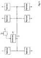
- FIG. 3 shows an arrangement of wheel modules (1, 2, 3, 4, 5, 6) and a central module (8), which to control the braking system of a three-axle vehicle, e.g. B. with a front axle and two rear axles, serves.
- the wheel modules (1, 2, 3, 4, 5, 6) are one below the other and with the central module (8) via the data bus system (7) connected.
- the wheel modules are all from same type, d. H. they have the one described in FIG. 1 Structure and that described in FIG. 2 Program structure.
- the central module (8) is with a Brake value transmitter (9) connected to the brake actuation emits a signal representing the driver. This signal is processed in the central module (8).
- the processing result is via the data bus system (7) the wheel modules (1, 2, 3, 4, 5, 6) as Brake value sent.
- the central module (8) preferably transmits the first time Commissioning of the brake system or the vehicle information about the wheel assignment of a wheel module to each of the wheel modules. This information is in a wheel module then in the non-volatile memory (23) saved and is continuously available from now on.
- the central module (8) and the brake value transmitter (9) can also be summarized in one unit.
- the brake value transmitter would be (9) via a suitable interface device directly connected to the data bus system (7).
- the brake value sent by the brake value transmitter then represents the driver's braking request.
- the determination the wheel assignment of the wheel modules in this case by using a diagnostic device that preferably also when commissioning the Brake system is connected to the data bus system (7), performed.
- the diagnostic tool is switched off after the Assignment procedure removed.
- the wheel modules (3, 4) are one Rear axle, e.g. B. the drive axle, the vehicle assigned.
- the wheel position parameters in the wheel modules (1, 2, 3, 4) are set such that the control signal of the control channel of the valve device (29) is supplied, the control channel number of the numbering of the corresponding wheel module according to FIG. 3.
- the control channel is in the wheel module (1) 1 defined as the main control channel in the wheel module (2)
- control channel 2 is main control channel and so on.
- the wheel modules (5, 6) are a further rear axle assigned to the vehicle.
- the wheel assignment of these wheel modules (5, 6) corresponds to the wheel modules (3, 4), which are also assigned to a rear axle been. Accordingly, in the wheel module (5) Control channel (3) has been defined as the main control channel, while in the wheel module (6) the control channel (4) is fixed has been. When using additional wheel modules these would depend on the type of vehicle axle which they are assigned a corresponding wheel assignment.
Landscapes
- Engineering & Computer Science (AREA)
- Transportation (AREA)
- Mechanical Engineering (AREA)
- Regulating Braking Force (AREA)
Abstract
Description
Die Erfindung betrifft ein Radmodul für ein Fahrzeug
mit einem elektrisch steuerbaren Bremssystem (EBS) zur
Steuerung der Bremskraft an wenigstens einem Rad des
Fahrzeuges gemäß dem Oberbegriff des Patentanspruchs 1.The invention relates to a wheel module for a vehicle
with an electrically controllable braking system (EBS)
Control of the braking force on at least one wheel of the
Vehicle according to the preamble of
Ein derartiges Radmodul ist aus der EP 0 467 112 B1 bekannt.Such a wheel module is known from EP 0 467 112 B1.
Das bekannte Radmodul ist Teil eines elektrisch steuerbaren Bremssystems, welches Radmoduln, Zentralmoduln sowie Gebereinrichtungen, wie z. B. einen Bremswertgeber, aufweist. Das bekannte Radmodul ist einem Rad eines Fahrzeuges zugeordnet. Mittels eines demselben Rad zugeordneten Drehgeschwindigkeitssensors wird ein die Drehgeschwindigkeit des Rades repräsentierendes Signal erzeugt und dem diesem Rad zugeordneten Radmodul zur Auswertung zugeführt. Eine in dem Radmodul angeordnete elektronische Steuereinrichtung mit einem Mikroprozessor wertet dieses Signal aus und sendet ein daraus berechnetes Geschwindigkeitssignal über ein Datenbussystem aus. Über das Datenbussystem sind mehrere Radmoduln, die jeweils ein Geschwindigkeitssignal aussenden, mit einem Zentralmodul verbunden. Das Zentralmodul wertet die vom Datenbussystem empfangenen Geschwindigkeitssignale aus und berechnet hieraus z. B. eine Fahrzeugreferenzgeschwindigkeit, die für eine Antiblockier-Regelung erforderlich ist. Diese Fahrzeugreferenzgeschwindigkeit und gegebenenfalls weitere, für eine Antiblockier-Regelung erforderliche Rechenergebnisse sendet das Zentralmodul sodann an die Radmoduln zurück, welche diese Daten dann für eine Antiblockier-Regelung an dem ihnen zugeordneten Rad verwenden.The known wheel module is part of an electrically controllable Braking system, which wheel modules, central modules and donor facilities such. B. a brake value transmitter, having. The known wheel module is a wheel one Assigned to the vehicle. Using the same bike assigned rotational speed sensor is a Signal representing the rotational speed of the wheel generated and the wheel module assigned to this wheel Evaluation fed. One arranged in the wheel module electronic control device with a microprocessor evaluates this signal and sends a calculated one Speed signal via a data bus system out. Several wheel modules are connected via the data bus system, which each send out a speed signal, connected to a central module. The central module evaluates the speed signals received by the data bus system and calculates z. B. a vehicle reference speed, for an anti-lock control is required. This vehicle reference speed and if necessary, further, for an anti-lock control sends required calculation results the central module then back to the wheel modules, which this data then for an anti-lock control use on the wheel assigned to them.
Demzufolge müssen über das Datenbussystem relativ viele Daten zwischen den daran angeschlossenen Moduln ausgetauscht werden.As a result, a relatively large number must be available via the data bus system Data exchanged between the modules connected to it become.
Der Erfindung liegt daher die Aufgabe zugrunde, ein Radmodul sowie ein Bremssystem anzugeben, bei dem der Aufwand für die Datenübertragung verringert ist.The invention is therefore based on the object Specify wheel module and a braking system in which the Data transmission effort is reduced.
Diese Aufgabe wird durch die im Patentanspruch 1 angegebene
Erfindung gelöst. Weiterbildungen und vorteilhafte
Ausgestaltungen der Erfindung sind in den Unteransprüchen
angegeben.This object is achieved by the specified in
Die Erfindung hat den Vorteil, daß der Aufwand für die
Datenübertragung zwischen den Moduln des Bremssystems
auf ein äußerst geringes Maß reduziert wird, indem die
für eine Bremsensteuerung mit Antiblockier-Regelung
notwendigen, aus den Eingangssignalen berechneten Rechenergebnisse,
wie z. B. eine Fahrzeugreferenzgeschwindigkeit,
Schlupfsignale, Beschleunigungssignale,
Bremskraftverringerungs-, Halte- und/oder Wiederaufbausignale,
nicht an zentraler Stelle, d. h. in einem Zentralmodul,
berechnet und über das Datenbussystem an die
Radmoduln übertragen wird, sondern direkt in einem Radmodul
lokal berechnet wird. Da insbesondere eine Antiblockier-Regelung
sehr zeitkritisch ist, ist außerdem
eine Verbesserung der Regelgüte erzielbar, weil Zeitverzögerungen,
die infolge einer Datenübertragung zwischen
dem Zentralmodul und dem Radmodul entstehen, vermieden
werden. Ein weiterer Vorteil des erfindungsgemäßen
Radmoduls besteht darin, daß es auch ohne Zentralmodul
bzw. auch nach Ausfall des Zentralmoduls ohne
Einschränkungen hinsichtlich der Antiblockier-Regelverfahren
betrieben werden. So kann sogar ohne Zentralmodul
z. B. eine sogenannte Modifizierte Individualregelung,
wie z.B. aus der DE 28 51 107 C2 bekannt, an einer
lenkbaren Achse zur Abschwächung von Giermomentänderungen
ausgeführt werden. Auch weitere, dem Fachmann
im einzelnen geläufige Regelungsprinzipien wie z.B. Variable
Achsregelung oder Modifizierte Achsregelung können
sowohl mit als auch ohne Zentralmodul ausgeführt
werden.The invention has the advantage that the effort for
Data transmission between the modules of the braking system
is reduced to an extremely low level by the
for brake control with anti-lock control
necessary calculation results calculated from the input signals,
such as B. a vehicle reference speed,
Slip signals, acceleration signals,
Brake force reduction, stop and / or reconstruction signals,
not in a central location, d. H. in a central module,
calculated and via the data bus system to the
Wheel modules is transmitted, but directly in a wheel module
is calculated locally. Because in particular an anti-lock control
is also very time critical
an improvement in the control quality can be achieved because of time delays,
which result from a data transfer between
the central module and the wheel module avoided
become. Another advantage of the invention
Wheel module is that it is also without a central module
or even if the central module fails
Limitations regarding the anti-lock control procedure
operate. So even without a central module
e.g. B. a so-called modified individual regulation,
such as. known from
Ein weiterer Vorteil der Erfindung besteht darin, daß in jedem Radmodul das gleiche Steuerprogramm vorgesehen sein kann, so daß unabhängig von der Zahl der eingesetzten Radmoduln in einem Fahrzeug nur ein einziges Steuerprogramm zu erstellen ist, wodurch der Entwicklungsaufwand relativ gering ist.Another advantage of the invention is that the same control program is provided in each wheel module can be so that regardless of the number of used Only one wheel module in a vehicle Control program is to be created, reducing the development effort is relatively small.
Gemäß einer vorteilhaften Weiterbildung der Erfindung wird eine Festlegung der Radzuordnung eines Radmoduls durch Eingabe eines Radpositionsparameters, der in eine in dem Radmodul vorgesehene elektronische Steuereinrichtung eingegeben wird, vorgenommen. Dies hat den Vorteil, daß zunächst identische Radmoduln hergestellt werden können, welche erst zu einem relativ späten Zeitpunkt, z. B. bei ihrer Installation in einem Fahrzeug, ihre Funktion im Detail zugewiesen bekommen. Eine Radzuordnung ist beispielsweise notwendig, um an einer lenkbaren Achse eines Fahrzeuges die Antiblockier-Regelung nach einem anderen Prinzip, z. B. als bereits erwähnte Modifizierte Individualregelung, durchzuführen als an einer nicht lenkbaren Achse des Fahrzeuges, an der beispielsweise eine sogenannte Individualregelung durchgeführt wird.According to an advantageous development of the invention becomes a definition of the wheel assignment of a wheel module by entering a wheel position parameter that is in a electronic control device provided in the wheel module is entered. This has the Advantage that initially identical wheel modules are manufactured can be, which only at a relatively late Time, e.g. B. when installed in a vehicle, get their function assigned in detail. A Wheel assignment is necessary, for example, in order to steerable axle of a vehicle the anti-lock control according to another principle, e.g. B. as already mentioned Modified individual regulation to be carried out than on a non-steerable axle of the vehicle for example a so-called individual regulation is carried out.
Die Eingabe des Radpositionsparameters kann z. B. manuell durch Bedienung eines Diagnosegerätes, welches den Radmoduln entsprechende Daten übermittelt, vorgenommen werden. Falls in dem Bremssystem ein Zentralmodul vorgesehen ist, dann nimmt gemäß einer vorteilhaften Weiterbildung der Erfindung das Zentralmodul die Zuweisung der Radzuordnung automatisch vor, z. B. einmalig bei Erstinstallation der Bremsanlage. Hierfür sind dann in dem Zentralmodul Informationen über die Radzuordnung und die Bremsanlage gespeichert.Entering the wheel position parameter can e.g. B. manually by operating a diagnostic device that the Corresponding data transmitted to wheel modules become. If a central module is provided in the brake system is then takes according to an advantageous development of the invention the central module the assignment the wheel assignment automatically before, for. B. once at First installation of the brake system. Then in the central module information about the wheel allocation and saved the braking system.
Zur Durchführung bestimmter Regelungsfunktionen, bei denen Geschwindigkeitsinformationen mehrerer Räder vorliegen müssen, z. B. Modifizierte Individualregelung, ist es notwendig, daß bestimmte Radmoduln das aus dem Signal des ihnen zugeordneten Drehgeschwindigkeitssensors berechnete Geschwindigkeitssignal über das Datenbussystem übertragen. Gemäß einer vorteilhaften Weiterbildung der Erfindung übertragen jedoch nicht alle Radmoduln ihr jeweiliges Geschwindigkeitssignal, sondern nur diejenigen Radmoduln, deren Geschwindigkeitssignale in anderen Radmoduln benötigt werden. Hierdurch wird der Aufwand für die Datenübertragung gering gehalten. In vorteilhafter Weise kann die elektronische Steuereinrichtung eines Radmoduls anhand des Radpositionsparameters erkennen, ob das Geschwindigkeitssignal über das Datenbussystem übertragen werden soll oder nicht.To perform certain control functions at which have speed information from several wheels need, e.g. B. Modified individual regulations, it is necessary that certain wheel modules from the Signal of the rotation speed sensor assigned to them calculated speed signal via the data bus system transfer. According to an advantageous development However, the invention does not transmit all wheel modules their respective speed signal, but only those wheel modules whose speed signals are required in other wheel modules. This will the effort for data transmission was kept low. The electronic control device can advantageously of a wheel module based on the wheel position parameter detect whether the speed signal is above the data bus system is to be transmitted or not.
Gemäß einer vorteilhaften Weiterbildung der Erfindung übertragen Radmoduln, die infolge der Festlegung der Radzuordnung an einer dritten oder weiteren Fahrzeugachse, d. h. nicht an der lenkbaren oder der angetriebenen Achse, angeordnet sind, kein Geschwindigkeitssignal über das Datenbussystem. Hierdurch ist das Bremssystem modular um eine im Prinzip unbegrenzte Anzahl von Radmoduln je nach Anforderungen durch das Fahrzeug erweiterbar, ohne daß der Aufwand für die Datenübertragung nennenswert steigt oder besondere Anpassungsarbeiten erforderlich wären.According to an advantageous development of the invention transmit wheel modules that result from the determination of the Wheel assignment on a third or further vehicle axle, d. H. not on the steerable or the driven Axis, are arranged, no speed signal via the data bus system. This is it Braking system modular by an unlimited number in principle of wheel modules depending on the requirements by the Vehicle expandable without the expense of data transmission appreciable increases or special adjustment work would be required.
Eine vorteilhafte Ausgestaltung der Erfindung besteht darin, ein Bremssystem mit mehreren Radmoduln der zuvor beschriebenen Art sowie mit einem Zentralmodul auszustatten, wobei diese Moduln über ein oder mehrere Datenbussysteme zum Austausch von Informationen miteinander verbunden sind. Das Zentralmodul dient hierbei vorzugsweise zur Ausführung zentraler, nur einmal in dem Fahrzeug benötigter Bremsensteuerungsfunktionen. So werden dem Zentralmodul vorzugsweise sogenannte Bremsenmanagement-Funktionen zugewiesen. Hierunter versteht man beispielsweise eine achslastabhängige Bremskraftverteilungsfunktion, eine einen gleichmäßigen Verschleiß der Bremsbeläge fördernde Bremskraftverteilungsfunktion oder auch eine Regelung der Fahrzeugverzögerung. Das Zentralmodul kann auch weitere zentrale Funktionen, wie z. B. eine Motorregelung als Teil einer Antriebsschlupfregelung, ausführen.An advantageous embodiment of the invention exists therein, a braking system with several wheel modules from the previous one described type and to be equipped with a central module, these modules via one or more data bus systems to exchange information with each other are connected. The central module is preferably used here to execute more centrally, only once in the Vehicle required brake control functions. So the central module are preferably so-called brake management functions assigned. This means for example, an axle load-dependent braking force distribution function, an even wear of the brake force distribution function promoting the brake pads or a regulation of vehicle deceleration. The central module can also be other central Functions such as B. an engine control as part of a Execute traction control.
Die Erfindung wird im folgenden anhand eines Ausführungsbeispiels unter Zuhilfenahme von Zeichnungen näher erläutert.The invention is described below using an exemplary embodiment with the help of drawings explained.
Es zeigen
- Fig. 1
- das erfindungsgemäße Radmodul in schematischer Darstellung und
- Fig. 2
- einen schematischen Ablaufplan der in einem Radmodul zur Antiblockier-Regelung auszuführenden Programmschritte und
- Fig. 3
- ein elektrisch gesteuertes Bremssystem mit mehreren Radmoduln und einem Zentralmodul.
- Fig. 1
- the wheel module according to the invention in a schematic representation and
- Fig. 2
- a schematic flow chart of the program steps to be carried out in a wheel module for anti-lock control and
- Fig. 3
- an electrically controlled braking system with several wheel modules and a central module.
In den Figuren werden gleiche Bezugszeichen für einander entsprechende Teile und Funktionen verwendet.In the figures, the same reference numerals are used for one another appropriate parts and functions used.
In der Fig. 1 ist der innere Aufbau eines Radmoduls (1) schematisch dargestellt. Von einer in dem Radmodul (1) angeordneten elektronischen Steuereinrichtung ist zur besseren Übersicht nur ein Mikrocomputer (28), ein nichtflüchtiger Speicherbaustein (23) und ein Ausgangsverstärker (35) dargestellt. Weitere, in der Praxis üblicherweise eingesetzte und dem Fachmann bekannte zusätzliche Schaltungsteile, wie Pegelanpassungen, Analog-/Digitalwandler, Treiber usw. sind nicht näher dargestellt.1 is the internal structure of a wheel module (1) shown schematically. From one in the wheel module (1) arranged electronic control device is for only a microcomputer (28) provides a better overview non-volatile memory chip (23) and an output amplifier (35). Further, usually in practice used and known to the expert additional Circuit parts such as level adjustments, analog / digital converters, Drivers, etc. are not shown in detail.
Der Mikrocomputer (28), der vorzugsweise vom Typ 68010 der Firma Motorola bzw. ein anderer 16 Bit Mikrocomputer ist, wird über eine elektrische Leitung (24) mit Betriebsspannung versorgt. Der Mikrocomputer (28) ist über ein Datenbussystem (7) mit weiteren Radmoduln und gegebenenfalls auch einem Zentralmodul verbunden. Als Datenbussystem (7) kann vorzugsweise ein CAN-Datenbus eingesetzt werden.The microcomputer (28), which is preferably of the 68010 type from Motorola or another 16 bit microcomputer is with an electrical line (24) Operating voltage supplied. The microcomputer (28) is via a data bus system (7) with further wheel modules and optionally also connected to a central module. As Data bus system (7) can preferably be a CAN data bus be used.
Der Mikrocomputer (28) gibt bei Bedarf über einen Ausgangsverstärker (35) ein Stellsignal an eine Ventileinrichtung (29) ab. Die Ventileinrichtung (29) ist als 3/3-Wegeventil ausgebildet. Mittels der Ventileinrichtung (29) kann in Abhängigkeit von dem Stellsignal ein ihr über eine Drückmittelleitung (25) zugeführter Vorratsdruck (PB) ausgangsseitig an einen mit dem Radmodul verbundenen Bremszylinder (30), welcher zur mechanischen Betätigung einer mit einem Rad (31) verbundenen Radbremse dient, weitergeleitet werden. Die Ventileinrichtung (29) und der Bremszylinder (30) bilden somit einen Aktuator zur Einstellung der Bremskraft an dem Rad (31).If necessary, the microcomputer (28) sends an actuating signal to a valve device (29) via an output amplifier (35). The valve device (29) is designed as a 3/3-way valve. Depending on the control signal, the valve device (29) can supply a supply pressure (P B ) supplied to it via a pressure medium line (25) on the output side to a brake cylinder (30) connected to the wheel module, which is connected to a wheel (31) for mechanical actuation Wheel brake is used to be forwarded. The valve device (29) and the brake cylinder (30) thus form an actuator for adjusting the braking force on the wheel (31).
Bei entsprechenden anderen Stellsignalen kann mittels der Ventileinrichtung (29) der Bremsdruck in dem Bremszylinder (30) reduziert oder auf einem vorhandenen Wert gehalten werden. In den beiden letztgenannten Fällen ist der Bremszylinder (30) nicht mit dem Vorratsdruck (PB) verbunden. Der jeweils in dem Bremszylinder (30) vorliegende Bremsdruck, welcher die Ist-Bremskraft repräsentiert, wird mittels eines Drucksensors (33) in ein elektrisches Signal umgewandelt, welches dem Mikrocomputer (28) zugeführt wird.In the case of corresponding other actuating signals, the brake pressure in the brake cylinder (30) can be reduced or kept at an existing value by means of the valve device (29). In the latter two cases, the brake cylinder (30) is not connected to the supply pressure (P B ). The brake pressure present in the brake cylinder (30), which represents the actual braking force, is converted by means of a pressure sensor (33) into an electrical signal which is fed to the microcomputer (28).
Des weiteren wird dem Mikrocomputer (28) ein mittels eines Drehgeschwindigkeitssensors (32) erzeugtes Signal über eine elektrische Leitung (34) zur Auswertung zugeführt. Der Drehgeschwindigkeitssensor (32) ist vorzugsweise als elektromagnetisch wirkender Impulsdrehzahlgeber ausgebildet und wirkt mit einem in der Fig. 1 nicht dargestellten, mit einer Vielzahl von Zähnen versehenen Polrad zusammen. Das infolge von Drehungen des Polrades erzeugte Signal ist eine Folge von Spannungsimpulsen, deren zeitlicher Abstand voneinander ein Maß für die Drehgeschwindigkeit des Rades (31) ist. Der Mikrocomputer (28) berechnet aus den zeitlichen Abständen unter Verwendung zusätzlicher Informationen, die in dem Radmodul gespeichert sind, wie z.B. dem Umfang des Rades (31), ein Geschwindigkeitssignal.Furthermore, the microcomputer (28) is a means a signal generated by a rotational speed sensor (32) Via an electrical line (34) supplied for evaluation. The rotational speed sensor (32) is preferred as an electromagnetic pulse encoder trained and does not work with one in FIG. 1 shown, provided with a variety of teeth Pole wheel together. This is due to rotations of the magnet wheel generated signal is a sequence of voltage pulses, their temporal distance from each other is a measure of Speed of rotation of the wheel (31) is. The microcomputer (28) calculated from the time intervals below Use of additional information in the wheel module are stored, e.g. the circumference of the wheel (31), a speed signal.
Über eine elektrische Leitung (22) werden dem Mikrocomputer (28) Signale weiterer Sensoren, z. B. von einem Bremsbelag-Verschleißsensor, zugeführt. Über die Leitung (22) kann der Mikrocomputer (28) außerdem Daten von einem nichtflüchtigen Speicherbaustein (23), z. B. einem EEPROM, lesen bzw. Daten dorthin schreiben. In dem Speicherbaustein (23) sind Informationen wie z.B. der Radpositionsparameter und der Umfang des Rades (31) speicherbar. The microcomputer is connected to an electrical line (22) (28) Signals from other sensors, e.g. B. from one Brake pad wear sensor supplied. About the line (22) the microcomputer (28) can also store data from a non-volatile memory chip (23), e.g. B. an EEPROM, read or write data there. In the memory chip (23) contains information such as the wheel position parameter and the circumference of the wheel (31) storable.
Der Mikrocomputer (28) empfängt von dem Datenbussystem (7) einen Bremswert, der die an dem Rad (31) einzustellende Soll-Bremskraft angibt. Der Bremswert wird entweder direkt von einem mit dem Bremspedal verbundenem Bremswertgeber oder von einem mit dem Bremswertgeber verbundenen Zentralmodul ausgesandt. Das Radmodul hat die Aufgabe, diesen Bremswert in eine entsprechende Bremskraft bzw. einen Bremsdruck in den Bremszylinder (30) umzuwandeln, so daß das Fahrzeug nach Maßgabe der Bremspedalbetätigung gebremst wird.The microcomputer (28) receives from the data bus system (7) a braking value which is to be set on the wheel (31) Specifies target braking force. The braking value is either directly from one connected to the brake pedal Brake value transmitter or from one with the brake value transmitter connected central module. The wheel module has the task of converting this braking value into a corresponding one Braking force or a brake pressure in the brake cylinder (30) convert so that the vehicle according to the Brake pedal actuation is braked.
Falls hierbei durch Auswertung des von dem Drehgeschwindigkeitssensor (32) gelieferten Signals ein beginnendes Blockieren des Rades (31) erkannt wird, wird der Bremsdruck abweichend von dem infolge des Bremswertes normalerweise einzustellenden Bremsdruck im Rahmen eines Antiblockier-Regelungsverfahrens in bekannter Weise verringert bzw. durch kontinuierliche Anpassungen derart moduliert, daß der Schlupf des Rades (31) auf einen konstanten Wert von etwa 20% eingeregelt wird. Im Rahmen dieses Antiblockier-Regelungsverfahrens werden in dem Mikrocomputer (28) neben dem von dem Drehgeschwindigkeitssensor (32) erzeugten Geschwindigkeitssignal noch weitere Geschwindigkeitssignale von anderen Radmoduln berücksichtigt.If in this case by evaluating the speed of rotation sensor (32) delivered signal an beginning Blocking the wheel (31) is detected the brake pressure deviates from that due to the braking value brake pressure normally to be set in the frame an anti-lock control method in a known Reduced way or through continuous adjustments modulated so that the slip of the wheel (31) a constant value of about 20% is set. in the Under this anti-lock control procedure in the microcomputer (28) next to that of the rotational speed sensor (32) generated speed signal other speed signals from others Wheel modules taken into account.
Das Radmodul (1) kann auch in den Bremszylinder (30) baulich integriert sein, was einen sehr kompakten Aufbau und eine vereinfachte Montage ergibt. The wheel module (1) can also be inserted into the brake cylinder (30) be structurally integrated, which is a very compact structure and results in a simplified assembly.
In einer anderen vorteilhaften Ausführungsform können statt eines Bremszylinders auch mehrere Bremszylinder, die den Rädern einer Rad- oder Achsgruppe des Fahrzeuges zugeordnet sind und mit dem gleichen Bremsdruck beaufschlagt werden sollen, mit dem Radmodul verbunden werden. In diesem Fall wäre in dem Radmodul eine Anschlußmöglichkeit für einen oder mehrere weitere Drehgeschwindigkeitssensoren vorgesehen, die zur Ermittlung der Drehgeschwindigkeiten der übrigen Räder der Rad- oder Achsgruppe dienen.In another advantageous embodiment, can instead of one brake cylinder, several brake cylinders, the wheels of a wheel or axle group of the vehicle are assigned and applied with the same brake pressure are to be connected to the wheel module become. In this case there would be a connection option in the wheel module for one or more additional rotation speed sensors provided for the determination the rotational speeds of the other wheels of the wheel or Serve axis group.
In der Fig. 2 ist beispielhaft eine Abfolge von einzelnen Programmschritten eines Antiblockier-Regelungsverfahrens, wie es in dem Mikrocomputer (28) ausgeführt wird, dargestellt. Das Antiblockier-Regelungsverfahren besteht vom Prinzip her einerseits aus gleichartigen, den jeweiligen Rädern zuzuordnenden Programmschritten (101, 102, 103, 104, 105, 201, 202, 203, 204, 205, 301, 302, 303, 304, 305, 401, 402, 403, 404, 405) und andererseits aus gemeinsamen, für mehrere oder alle Räder gültigen Programmschritten (10, 11). Die gleichartigen, den Rädern zuzuordnenden Programmschritte werden auch als Regelkanäle bezeichnet.2 shows a sequence of individual examples Program steps of an anti-lock control method, as stated in the microcomputer (28) is shown. The anti-lock control procedure basically consists of similar Program steps to be assigned to the respective wheels (101, 102, 103, 104, 105, 201, 202, 203, 204, 205, 301, 302, 303, 304, 305, 401, 402, 403, 404, 405) and on the other hand from common, for several or all bikes valid program steps (10, 11). The like, Program steps to be assigned to the wheels are also referred to as control channels.
In dem Beispiel gemäß Fig. 2 sind vier Regelkanäle dargestellt.
Der Regelkanal 1 besteht aus den Programmschritten
(101, 102, 103, 104, 105), der Regelkanal 2
besteht aus den Programmschritten (201, 202, 203, 204,
205), der Regelkanal 3 besteht aus den Programmschritten
(301, 302, 303, 304, 305) und der Regelkanal 4 besteht
aus den Programmschritten (401, 402, 403, 404,
405). Je nach Anwendungsfall kann auch eine andere Anzahl
von Regelkanälen vorgesehen sein, z.B. zwei oder
drei Regelkanäle.In the example according to FIG. 2, four control channels are shown.
Jeder der Regelkanäle ist grundsätzlich für die Verarbeitung eines Eingangssignals von einem Drehgeschwindigkeitssensor und zur Ausgabe eines Stellsignals für eine Ventileinrichtung vorgesehen. Das dargestellte Antiblockier-Regelungsverfahren könnte somit in einem entsprechenden Steuergerät auch zur Antiblockier-Regelung von vier Rädern eines Fahrzeuges im Sinne eines Vierkanal-Antiblockiersystems verwendet werden.Each of the control channels is basically for processing an input signal from a rotational speed sensor and to output an actuating signal for a valve device is provided. The anti-lock control procedure shown could therefore be in one corresponding control unit also for anti-lock control of four wheels of a vehicle in the sense of one Four-channel anti-lock braking system can be used.
Im Unterschied zu einem Vierkanal-Antiblockiersystem weist jedoch die in dem Radmodul (1) vorgesehene elektronische Steuereinrichtung nur für einen Drehgeschwindigkeitssensor (32) und eine Ventileinrichtung (29) Anschlußmöglichkeiten auf. Aus diesem Grunde wird das Signal von dem Drehgeschwindigkeitssensor (32) nur einem der Regelkanäle, der im folgenden als Hauptregelkanal bezeichnet wird, zur Auswertung zugeführt. Die übrigen Regelkanäle, im folgenden als Zusatzregelkanäle bezeichnet, erhalten ihre Geschwindigkeitsinformation von dem Datenbussystem (7). Für die Auswahl der Datenquelle für die Geschwindigkeitsinformation ist in jedem Regelkanal ein logischer Umachalter (106, 206, 306, 406) vorgesehen, welcher mittels Programmierung des Radmoduls im Rahmen der Radzuordnung eingestellt werden kann.In contrast to a four-channel anti-lock braking system however, has the electronic provided in the wheel module (1) Control device for only one speed sensor (32) and a valve device (29) connection options on. For this reason, the signal only one of the rotational speed sensor (32) of the control channels, hereinafter referred to as the main control channel is referred for evaluation. The remaining Control channels, hereinafter referred to as additional control channels, get their speed information from the data bus system (7). For the selection of the data source for the speed information is in each control channel a logical switch (106, 206, 306, 406) provided by programming the wheel module can be set within the wheel allocation can.
Ebenso ist für die Weitergabe der von den vier Regelkanälen jeweils berechneten Stellsignale ein logischer Auswahlschalter (12) vorgesehen, welcher auf die gleiche Weise programmierbar ist und vorzugsweise derart programmiert wird, daß das Steilsignal von dem Hauptregelkanal an die Ventileinrichtung (29) ausgegeben wird.Likewise, for the transfer of the four control channels each calculated control signal is a logical one Selection switch (12) is provided, which on the same Is programmable and preferably such is programmed that the steep signal from the main control channel is output to the valve device (29).
Im Beispiel gemäß Fig. 2 wurde der Regelkanal 1 per
Radzuordnung des Radmoduls als Hauptregelkanal definiert.
Der Regelkanal 1 ist, ebenso wie der Regelkanal
2, für eine Antiblockier-Regelung eines an einer lenkbaren
Vorderachse eines Fahrzeuges angeordneten Rades
vorgesehen.In the example according to FIG. 2,
Zwischen der Eingabe der Geschwindigkeitssignale in die Regelkanäle und der Ausgabe des Stellsignals werden verschiedene, dem Fachmann im einzelnen bekannte Programmschritte einer Antiblockier-Regelung ausgeführt. Beispielhaft seien hier die Programmschritte
- Geschwindigkeitssignal berechnen (101, 201, 301, 401),
- Radreferenzgeschwindigkeit berechnen (102, 202, 302, 402),
- Fahrzeugreferenzgeschwindigkeit berechnen (10),
- Radschlupf berechnen (103, 203, 303, 403),
- Verzögerung/Beschleunigung berechnen (104, 204, 304, 404),
- Modifizierte Individualregelung (11) und
- Stellsignal berechnen (105, 205, 305, 405)
- Calculate speed signal (101, 201, 301, 401),
- Calculate wheel reference speed (102, 202, 302, 402),
- Calculate vehicle reference speed (10),
- Calculate wheel slip (103, 203, 303, 403),
- Calculate deceleration / acceleration (104, 204, 304, 404),
- Modified individual regulation (11) and
- Calculate control signal (105, 205, 305, 405)
Die Programmschritte (101, 201, 301, 401) sind für eine
Umsetzung des von dem Drehgeschwindigkeitssensor (32)
abgegebenen Signals, z.B. der Folge von Impulsen mit
veränderlichem zeitlichen Abstand, in das von den nachfolgenden
Programmschritten verarbeitbare Geschwindigkeitssignal
vorgesehen. Im vorliegenden Ausführungsbeispiel
wird das Signal von dem Drehgeschwindigkeitssensor
(32) in dem Programmschritt (101) verarbeitet. Die
Regelkanäle 2, 3 und 4 erhalten, wie erwähnt, ihre Geschwindigkeitsinformation
von dem Datenbussystem (7).
Das in dem Programmschritt (101) berechnete Geschwindigkeitssignal
wird neben der Verwendung in dem Regelkanal
1 außerdem auf dem Datenbussystem (7) ausgesendet
(nicht dargestellt).The program steps (101, 201, 301, 401) are for one
Implementation of the speed sensor (32)
output signal, e.g. the sequence of impulses with
variable time interval in which of the following
Program steps processable speed signal
intended. In the present embodiment
the signal from the rotation speed sensor
(32) processed in program step (101). The
Wie aus der Fig. 2 hervorgeht, wird für jeden Regelkanal eine eigene, radbezogene Referenzgeschwindigkeit, die sogenannte Radreferenzgeschwindigkeit, berechnet (Programmschritte 102, 202, 302, 402). In einem darauffolgenden, gemeinsamen Programmschritt (10) wird aus allen zuvor berechneten Radreferenzgeschwindigkeiten als erstes Zwischenergebnis der Berechnungen eine gemeinsame Fahrzeugreferenzgeschwindigkeit berechnet.As is apparent from Fig. 2, for each control channel a separate, wheel-related reference speed, the so-called wheel reference speed (Program steps 102, 202, 302, 402). In a subsequent common program step (10) is made all previously calculated wheel reference speeds a common intermediate result of the calculations Vehicle reference speed calculated.
Sodann wird unter Zuhilfenahme der gemeinsamen Fahrzeugreferenzgeschwindigkeit in jedem Regelkanal ein Radschlupf für jedes Rad berechnet (Programmschritte 103, 203, 303, 403). Des weiteren wird ebenfalls für jedes Rad in jedem Regelkanal die momentane Verzögerung bzw. Beschleunigung berechnet (Programmischritte 104, 204, 304, 404).Then, using the common vehicle reference speed in each control channel Wheel slip calculated for each wheel (program steps 103, 203, 303, 403). Furthermore, also for every wheel in every control channel the current deceleration or acceleration calculated (program steps 104, 204, 304, 404).
In einem weiteren Programmschritt (11) wird für die Regelkanäle
1 und 2 ein weiteres Zwischenergebnis berechnet,
welches bei der abschließenden Berechnung des
Stellsignals für die Ventileinrichtung eine Abschwächung
des Giermoments an der Vorderachse im Sinne der
bereits erwähnten Modifizierten Individualregelung bewirkt.In a further program step (11) for the
Unter Anwendung dieses weiteren Zwischenergebnisses
wird daraufhin in den einzelnen Regelkanälen 1 und 2
ein jeweiliges Stellsignal berechnet.Using this further interim result
is then in the
Bei den den Hinterrädern eines Fahrzeuges zuzuordnenden
Regelkanälen 3 und 4 wird im vorliegenden Ausführungsbeispiel
eine sogenannte Individualregelung vorgenommen,
d. h. es wird kein Zwischenergebnis für eine Modifizierte
Individualregelung berechnet. Daher wird ohne
Berechnung weiterer Zwischenergebnisse in den Regelkanälen
3 und 4 jeweils ein Steilsignal berechnet.For those assigned to the rear wheels of a
Falls an den Hinterrädern z.B. eine Variable Achsregelung
zum Einsatz käme, wäre zwischen den Programmschritten
(304, 404) und (305, 405) ein für die Regelkanäle
3 und 4 gemeinsamer Programmschritt analog zu
dem Programmschritt (11) vorgesehen, in dem dann Rechenschritte
für die zuvor genannte Variable Achsregelung
auszuführen wären.If on the rear wheels e.g. a variable axis control
would be used would be between the program steps
(304, 404) and (305, 405) one for the
Bei der zuvor beschriebenen Programmstruktur wird der Hauptregelkanal, der schließlich das Stellsignal für die Ventileinrichtung (29) erzeugt, infolge der direkten Anbindung an das Signal von dem dem Radmodul zugeordneten Drehgeschwindigkeitssensor (32) mit einer besonders häufig aktualisierten und somit sehr aktuellen Geschwindigkeitsinformation versorgt. Die Zusatzregelkanäle erhalten ihre Geschwindigkeitsinformation von dem Datenbussystem (7) in der Regel mit einer geringeren Aktualisierungshäufigkeit. Hierdurch ist eine hohe Regelgüte bei dynamischen Vorgängen an dem Rad, insbesondere bei der Antiblockier-Regelung, erzielbar.In the program structure described above, the Main control channel, which is finally the control signal for the valve device (29) generates as a result of the direct Connection to the signal from that assigned to the wheel module Rotational speed sensor (32) with a special frequently updated and therefore very current Speed information supplied. The additional control channels get their speed information from the data bus system (7) usually with a lower one Update frequency. This is a high Control quality in dynamic processes on the wheel, in particular with the anti-lock control, achievable.
Bei dem anhand der Fig. 2 beschriebenen Ausführungsbeispiel
enthält der Radpositionsparameter Informationen
über die Einstellung der logischen Schalter (106, 206,
306, 406, 12). Als Radpositionsparameter kann beispielsweise
auch die Nummer des Hauptregelkanals verwendet
werden, d.h. im vorliegenden Fall wäre der
Radpositionsparameter dann auf den Wert 1 zu setzen.
Die Einstellung der logischen Schalter (106, 206, 306,
406, 12) wäre dann von dem Mikrocomputer (28) von diesem
Wert abzuleiten.In the embodiment described with reference to FIG. 2
the wheel position parameter contains information
via the setting of the logic switches (106, 206,
306, 406, 12). For example, as a wheel position parameter
the number of the main control channel is also used
become, i.e. in the present case it would be
Then set the wheel position parameter to the
Statt der zuvor beschriebenen Programmstruktur mit vier Regelkanälen wäre auch die Verwendung einer anderen Anzahl von Regelkanälen denkbar.Instead of the previously described program structure with four Control channels would also use a different number of control channels conceivable.
In der Fig. 3 ist eine Anordnung von Radmoduln (1, 2, 3, 4, 5, 6) und einem Zentralmodul (8) dargestellt, die zur Steuerung der Bremsanlage eines dreiachsigen Fahrzeuges, z. B. mit einer Vorderachse und zwei Hinterachsen, dient. Die Radmoduln (1, 2, 3, 4, 5, 6) sind untereinander und mit dem Zentralmodul (8) über das Datenbussystem (7) verbunden. Die Radmoduln sind alle vom gleichen Typ, d. h. sie weisen den gemäß den Fig. 1 beschriebenen Aufbau und die gemäß Fig. 2 beschriebene Programmstruktur auf. Das Zentralmodul (8) ist mit einem Bremswertgeber (9) verbunden, der ein die Bremsbetätigung durch den Fahrer repräsentierendes Signal abgibt. Dieses Signal wird in dem Zentralmodul (8) verarbeitet. Das Verarbeitungsergebnis wird über das Datenbussystem (7) den Radmoduln (1, 2, 3, 4, 5, 6) als Bremswert zugesandt. Bei dieser Verarbeitung führt das Zentralmodul unter anderem zentrale, fahrzeugweite Bremsensteuerungsfunktionen, wie z. B. achslastabhängige Bremskraftverteilung, durch. Hierfür stehen dem Zentralmodul (8) Signale weiterer Sensoren bzw. Informationen von den Radmoduln zur Verfügung (nicht dargestellt).3 shows an arrangement of wheel modules (1, 2, 3, 4, 5, 6) and a central module (8), which to control the braking system of a three-axle vehicle, e.g. B. with a front axle and two rear axles, serves. The wheel modules (1, 2, 3, 4, 5, 6) are one below the other and with the central module (8) via the data bus system (7) connected. The wheel modules are all from same type, d. H. they have the one described in FIG. 1 Structure and that described in FIG. 2 Program structure. The central module (8) is with a Brake value transmitter (9) connected to the brake actuation emits a signal representing the driver. This signal is processed in the central module (8). The processing result is via the data bus system (7) the wheel modules (1, 2, 3, 4, 5, 6) as Brake value sent. This leads to this processing Central module including central, vehicle-wide Brake control functions, such as. B. axle load dependent Brake force distribution, by. This is what Central module (8) Signals from other sensors or information available from the wheel modules (not shown).
Das Zentralmodul (8) überträgt vorzugsweise bei erstmaliger Inbetriebnahme der Bremsanlage bzw. des Fahrzeuges eine Information über die Radzuordnung eines Radmoduls an jedes der Radmoduln. Diese Information wird in einem Radmodul dann in dem nichtflüchtigen Speicher (23) gespeichert und steht fortan ständig zur Verfügung.The central module (8) preferably transmits the first time Commissioning of the brake system or the vehicle information about the wheel assignment of a wheel module to each of the wheel modules. This information is in a wheel module then in the non-volatile memory (23) saved and is continuously available from now on.
Das Zentralmodul (8) und der Bremswertgeber (9) können auch in einer Baueinheit zusammengefaßt sein.The central module (8) and the brake value transmitter (9) can also be summarized in one unit.
Wie bereits erwähnt, ist es auch möglich, eine elektrische Steuerung der Bremsanlage ohne Verwendung des Zentralmoduls (8) nur Verwendung von Radmoduln (1, 2, 3, 4, 5, 6) durchzuführen. In diesem Fall wäre der Bremswertgeber (9) über eine geeignete Schnittstelleneinrichtung direkt mit dem Datenbussystem (7) verbunden. Der von dem Bremswertgeber ausgesandte Bremswert stellt dann den Bremswunsch des Fahrers dar. Die Festlegung der Radzuordnung der Radmoduln wird in diesem Fall durch Verwendung eines Diagnosegerätes, das vorzugsweise ebenfalls bei erstmaliger Inbetriebnahme der Bremsanlage mit dem Datenbussystem (7) verbunden wird, vorgenommen. Das Diagnosegerät wird nach Beendigung der Zuordnungsprozedur wieder entfernt.As already mentioned, it is also possible to use an electrical one Control of the brake system without using the central module (8) only use of wheel modules (1, 2, 3, 4, 5, 6). In this case the brake value transmitter would be (9) via a suitable interface device directly connected to the data bus system (7). The brake value sent by the brake value transmitter then represents the driver's braking request. The determination the wheel assignment of the wheel modules in this case by using a diagnostic device that preferably also when commissioning the Brake system is connected to the data bus system (7), performed. The diagnostic tool is switched off after the Assignment procedure removed.
In der in der Fig. 3 dargestellten Anordnung sind die
Radmoduln (1, 2) einer lenkbaren Vorderachse eines
Fahrzeuges zugeordnet. Die Radmoduln (3, 4) sind einer
Hinterachse, z. B. der Antriebsachse, des Fahrzeuges
zugeordnet. Die Radpositionsparameter in den Radmoduln
(1, 2, 3, 4) sind derart eingestellt, daß das Stellsignal
desjenigen Regelkanals der Ventileinrichtung (29)
zugeführt wird, dessen Regelkanalnummer der Numerierung
des entsprechenden Radmoduls gemäß Fig. 3 entspricht.
Mit anderen Worten, in dem Radmodul (1) ist der Regelkanal
1 als Hauptregelkanal definiert, in dem Radmodul
(2) ist der Regelkanal 2 Hauptregelkanal und so fort.In the arrangement shown in FIG. 3, the
Wheel modules (1, 2) of a steerable front axle
Assigned to the vehicle. The wheel modules (3, 4) are one
Rear axle, e.g. B. the drive axle, the vehicle
assigned. The wheel position parameters in the wheel modules
(1, 2, 3, 4) are set such that the control signal
of the control channel of the valve device (29)
is supplied, the control channel number of the numbering
of the corresponding wheel module according to FIG. 3.
In other words, the control channel is in the wheel module (1)
1 defined as the main control channel in the wheel module
(2)
Die Radmoduln (5, 6) sind einer weiteren Hinterachse des Fahrzeuges zugeordnet. Die Radzuordnung dieser Radmoduln (5, 6) ist entsprechend den Radmoduln (3, 4), die ebenfalls einer Hinterachse zugeordnet sind, vorgenommen worden. In dem Radmodul (5) ist demzufolge der Regelkanal (3) als Hauptregelkanal festgelegt worden, während in dem Radmodul (6) der Regelkanal (4) festgelegt worden ist. Bei Verwendung zusätzlicher Radmoduln würden diese je nach Art der Fahrzeugachse, welcher sie zugeordnet sind, eine entsprechende Radzuordnung erhalten.The wheel modules (5, 6) are a further rear axle assigned to the vehicle. The wheel assignment of these wheel modules (5, 6) corresponds to the wheel modules (3, 4), which are also assigned to a rear axle been. Accordingly, in the wheel module (5) Control channel (3) has been defined as the main control channel, while in the wheel module (6) the control channel (4) is fixed has been. When using additional wheel modules these would depend on the type of vehicle axle which they are assigned a corresponding wheel assignment.
Claims (12)
Applications Claiming Priority (2)
| Application Number | Priority Date | Filing Date | Title |
|---|---|---|---|
| DE19854788A DE19854788B4 (en) | 1998-11-27 | 1998-11-27 | Wheel module for a vehicle |
| DE19854788 | 1998-11-27 |
Publications (3)
| Publication Number | Publication Date |
|---|---|
| EP1006032A2 true EP1006032A2 (en) | 2000-06-07 |
| EP1006032A3 EP1006032A3 (en) | 2001-05-16 |
| EP1006032B1 EP1006032B1 (en) | 2007-05-30 |
Family
ID=7889239
Family Applications (1)
| Application Number | Title | Priority Date | Filing Date |
|---|---|---|---|
| EP99118947A Expired - Lifetime EP1006032B1 (en) | 1998-11-27 | 1999-09-25 | Vehicle wheel unit |
Country Status (4)
| Country | Link |
|---|---|
| US (1) | US6216080B1 (en) |
| EP (1) | EP1006032B1 (en) |
| JP (1) | JP2000198431A (en) |
| DE (2) | DE19854788B4 (en) |
Families Citing this family (12)
| Publication number | Priority date | Publication date | Assignee | Title |
|---|---|---|---|---|
| DE10135600A1 (en) | 2001-07-20 | 2003-02-06 | Wabco Gmbh & Co Ohg | Anti-lock braking system |
| DE10161498A1 (en) * | 2001-12-14 | 2003-06-26 | Wabco Gmbh & Co Ohg | Solenoid unit |
| DE10203207B4 (en) * | 2002-01-21 | 2015-03-26 | Volkswagen Ag | Electromechanical brake system |
| DE10221079B4 (en) | 2002-05-11 | 2011-01-20 | Wabco Gmbh | Anti-lock braking system for a wheeled vehicle |
| US20050071070A1 (en) * | 2003-09-26 | 2005-03-31 | Peter Nilsson | Brake system with distributed electronic control units responsive to sensor input |
| DE102004059546A1 (en) | 2004-12-09 | 2006-06-22 | Lucas Automotive Gmbh | Electronic system for operating an electromechanical parking brake system |
| FR2880322B1 (en) * | 2005-01-06 | 2007-08-17 | Haldex Brake Products Ltd | CENTRAL ELECTRONIC CONTROL NETWORK FOR SYSTEMS FOR CONTROLLING OR REGULATING THE SUSPENSION AND DYNAMICS OF VEHICLES ON HEAVY VEHICLES |
| DE102007015995B4 (en) * | 2007-04-03 | 2015-10-08 | Zf Friedrichshafen Ag | Axle module for a vehicle |
| DE102007021646A1 (en) * | 2007-05-09 | 2008-11-13 | Wabco Gmbh | modulator |
| DE102007059688A1 (en) * | 2007-12-12 | 2009-06-25 | Lucas Automotive Gmbh | Actuator device and method for driving the actuator device |
| DE102008009522B4 (en) | 2008-02-16 | 2021-12-16 | Zf Cv Systems Hannover Gmbh | Procedure for calibrating wheel speeds |
| DE102023203549A1 (en) * | 2023-04-19 | 2024-10-24 | Continental Automotive Technologies GmbH | Electromechanically operated wheel brake with central control electronics |
Citations (2)
| Publication number | Priority date | Publication date | Assignee | Title |
|---|---|---|---|---|
| DE2851107C2 (en) | 1978-11-25 | 1990-03-08 | Wabco Westinghouse Fahrzeugbremsen GmbH, 3000 Hannover | Circuit arrangement for improving the driving stability of vehicles equipped with anti-lock braking systems |
| EP0467112B1 (en) | 1990-07-17 | 1994-12-28 | WABCO GmbH | Electronic brake system for road vehicles |
Family Cites Families (9)
| Publication number | Priority date | Publication date | Assignee | Title |
|---|---|---|---|---|
| DE4122484A1 (en) * | 1991-07-06 | 1993-01-07 | Teves Gmbh Alfred | CIRCUIT FOR DETECTING WHEEL SENSOR DEFECTS |
| DE4135691C2 (en) | 1991-10-25 | 1998-04-16 | Aeg Westinghouse Transport | Arrangement for driving and braking control of vehicles that are equipped with several single wheel drive and braking modules |
| US5288139A (en) * | 1992-06-05 | 1994-02-22 | Allied-Signal Inc. | Electropneumatic braking system |
| DE19521175C1 (en) * | 1995-06-10 | 1996-07-11 | Continental Ag | Electrically or electronically controlled brake system |
| JPH09207745A (en) * | 1996-01-30 | 1997-08-12 | Nissan Motor Co Ltd | Anti-skid control device |
| DE19615203A1 (en) * | 1996-04-18 | 1997-10-23 | Bosch Gmbh Robert | Device for the detection of electromagnetic interference |
| DE19627731A1 (en) * | 1996-07-10 | 1998-01-15 | Abb Patent Gmbh | System for the drive and brake control of a rail vehicle |
| DE19634567B4 (en) * | 1996-08-27 | 2007-11-29 | Robert Bosch Gmbh | Electric brake system |
| DE19713252A1 (en) * | 1997-03-29 | 1998-10-01 | Bosch Gmbh Robert | Method and device for determining a variable describing the vehicle speed |
-
1998
- 1998-11-27 DE DE19854788A patent/DE19854788B4/en not_active Expired - Lifetime
-
1999
- 1999-09-25 EP EP99118947A patent/EP1006032B1/en not_active Expired - Lifetime
- 1999-09-25 DE DE59914357T patent/DE59914357D1/en not_active Expired - Lifetime
- 1999-11-24 JP JP11374544A patent/JP2000198431A/en active Pending
- 1999-11-29 US US09/450,863 patent/US6216080B1/en not_active Expired - Lifetime
Patent Citations (2)
| Publication number | Priority date | Publication date | Assignee | Title |
|---|---|---|---|---|
| DE2851107C2 (en) | 1978-11-25 | 1990-03-08 | Wabco Westinghouse Fahrzeugbremsen GmbH, 3000 Hannover | Circuit arrangement for improving the driving stability of vehicles equipped with anti-lock braking systems |
| EP0467112B1 (en) | 1990-07-17 | 1994-12-28 | WABCO GmbH | Electronic brake system for road vehicles |
Also Published As
| Publication number | Publication date |
|---|---|
| DE19854788A1 (en) | 2000-05-31 |
| DE19854788B4 (en) | 2009-12-03 |
| US6216080B1 (en) | 2001-04-10 |
| DE59914357D1 (en) | 2007-07-12 |
| EP1006032B1 (en) | 2007-05-30 |
| EP1006032A3 (en) | 2001-05-16 |
| JP2000198431A (en) | 2000-07-18 |
Similar Documents
| Publication | Publication Date | Title |
|---|---|---|
| EP0481043B1 (en) | System with interconnected controllers for motor vehicles | |
| EP0467112B2 (en) | Electronic brake system for road vehicles | |
| DE4227083C2 (en) | Electronic braking system, in particular for road vehicles | |
| EP0295396B1 (en) | Braking system for a steerable vehicle with 2 or more axles with at least rear axle driving | |
| EP0996558A1 (en) | Method and device for stabilizing a vehicle | |
| WO2009152981A1 (en) | Brake system and method for controlling a vehicle brake | |
| EP0949130B2 (en) | Control device for a vehicle brake system | |
| EP1006032B1 (en) | Vehicle wheel unit | |
| EP0189077B1 (en) | Brake pressure regulating device | |
| EP0985586B1 (en) | Anti lock system for a vehicle electromechanical brake system based on a fuzzy controller | |
| EP1125067A1 (en) | Method and device for monitoring the movements of an actuator | |
| DE19910048A1 (en) | Method and device for monitoring the movement of an actuator | |
| DE69722124T2 (en) | Method for determining a time of replacement and vehicle control device which is capable of displaying a time of replacement of an actuator | |
| EP1254792B1 (en) | Apparatus and method for controlling vehicle functions | |
| EP1233893B1 (en) | Method and device for controlling a brake system | |
| EP0927119A1 (en) | Method and device for determining a variable describing the speed of a vehicle | |
| EP0914998B1 (en) | Method for synchronising the brake forces between two parts of a vehicle unit | |
| DE102019108620B4 (en) | Method and control unit for controlling a steering brake function for a vehicle and braking system for a vehicle | |
| EP3500460B1 (en) | Method for adjusting brake pressures, brake system of a motor vehicle for carrying out the method, and motor vehicle comprising such a brake system | |
| EP2213535B1 (en) | ABS control method for a vehicle and vehicle with an ABS braking system | |
| EP1515881A1 (en) | Method and device for setting a desired longitudinal deceleration or longitudinal acceleration | |
| EP0629533B1 (en) | Method of operating a brake system for a vehicle | |
| EP1171334B1 (en) | Method and device for regulating braking effect | |
| DE4121473A1 (en) | DEVICE AND METHOD FOR ANTI-BLOCKING CONTROL FOR MOTOR VEHICLES | |
| EP3500461B1 (en) | Method for adjusting brake pressures, brake system of a motor vehicle for carrying out the method, and motor vehicle comprising such a brake system |
Legal Events
| Date | Code | Title | Description |
|---|---|---|---|
| PUAI | Public reference made under article 153(3) epc to a published international application that has entered the european phase |
Free format text: ORIGINAL CODE: 0009012 |
|
| AK | Designated contracting states |
Kind code of ref document: A2 Designated state(s): DE FR IT NL SE |
|
| AX | Request for extension of the european patent |
Free format text: AL;LT;LV;MK;RO;SI |
|
| PUAL | Search report despatched |
Free format text: ORIGINAL CODE: 0009013 |
|
| AK | Designated contracting states |
Kind code of ref document: A3 Designated state(s): AT BE CH CY DE DK ES FI FR GB GR IE IT LI LU MC NL PT SE |
|
| AX | Request for extension of the european patent |
Free format text: AL;LT;LV;MK;RO;SI |
|
| RIC1 | Information provided on ipc code assigned before grant |
Free format text: 7B 60T 8/00 A, 7B 60T 13/74 B |
|
| 17P | Request for examination filed |
Effective date: 20011116 |
|
| AKX | Designation fees paid |
Free format text: DE FR IT NL SE |
|
| GRAP | Despatch of communication of intention to grant a patent |
Free format text: ORIGINAL CODE: EPIDOSNIGR1 |
|
| RAP1 | Party data changed (applicant data changed or rights of an application transferred) |
Owner name: WABCO GMBH |
|
| GRAS | Grant fee paid |
Free format text: ORIGINAL CODE: EPIDOSNIGR3 |
|
| GRAA | (expected) grant |
Free format text: ORIGINAL CODE: 0009210 |
|
| AK | Designated contracting states |
Kind code of ref document: B1 Designated state(s): DE FR IT NL SE |
|
| REG | Reference to a national code |
Ref country code: SE Ref legal event code: TRGR |
|
| REF | Corresponds to: |
Ref document number: 59914357 Country of ref document: DE Date of ref document: 20070712 Kind code of ref document: P |
|
| ET | Fr: translation filed | ||
| PLBE | No opposition filed within time limit |
Free format text: ORIGINAL CODE: 0009261 |
|
| STAA | Information on the status of an ep patent application or granted ep patent |
Free format text: STATUS: NO OPPOSITION FILED WITHIN TIME LIMIT |
|
| 26N | No opposition filed |
Effective date: 20080303 |
|
| PGFP | Annual fee paid to national office [announced via postgrant information from national office to epo] |
Ref country code: DE Payment date: 20140930 Year of fee payment: 16 Ref country code: NL Payment date: 20140829 Year of fee payment: 16 |
|
| PGFP | Annual fee paid to national office [announced via postgrant information from national office to epo] |
Ref country code: SE Payment date: 20140918 Year of fee payment: 16 |
|
| PGFP | Annual fee paid to national office [announced via postgrant information from national office to epo] |
Ref country code: IT Payment date: 20140915 Year of fee payment: 16 |
|
| PGFP | Annual fee paid to national office [announced via postgrant information from national office to epo] |
Ref country code: FR Payment date: 20140926 Year of fee payment: 16 |
|
| REG | Reference to a national code |
Ref country code: DE Ref legal event code: R119 Ref document number: 59914357 Country of ref document: DE |
|
| PG25 | Lapsed in a contracting state [announced via postgrant information from national office to epo] |
Ref country code: IT Free format text: LAPSE BECAUSE OF NON-PAYMENT OF DUE FEES Effective date: 20150925 |
|
| REG | Reference to a national code |
Ref country code: SE Ref legal event code: EUG |
|
| PG25 | Lapsed in a contracting state [announced via postgrant information from national office to epo] |
Ref country code: SE Free format text: LAPSE BECAUSE OF NON-PAYMENT OF DUE FEES Effective date: 20150926 |
|
| REG | Reference to a national code |
Ref country code: NL Ref legal event code: MM Effective date: 20151001 |
|
| REG | Reference to a national code |
Ref country code: FR Ref legal event code: ST Effective date: 20160531 |
|
| PG25 | Lapsed in a contracting state [announced via postgrant information from national office to epo] |
Ref country code: DE Free format text: LAPSE BECAUSE OF NON-PAYMENT OF DUE FEES Effective date: 20160401 |
|
| PG25 | Lapsed in a contracting state [announced via postgrant information from national office to epo] |
Ref country code: FR Free format text: LAPSE BECAUSE OF NON-PAYMENT OF DUE FEES Effective date: 20150930 Ref country code: NL Free format text: LAPSE BECAUSE OF NON-PAYMENT OF DUE FEES Effective date: 20151001 |