EP1006032A2 - Module de roue pour une voiture - Google Patents
Module de roue pour une voiture Download PDFInfo
- Publication number
- EP1006032A2 EP1006032A2 EP99118947A EP99118947A EP1006032A2 EP 1006032 A2 EP1006032 A2 EP 1006032A2 EP 99118947 A EP99118947 A EP 99118947A EP 99118947 A EP99118947 A EP 99118947A EP 1006032 A2 EP1006032 A2 EP 1006032A2
- Authority
- EP
- European Patent Office
- Prior art keywords
- wheel
- signal
- module
- vehicle
- control
- Prior art date
- Legal status (The legal status is an assumption and is not a legal conclusion. Google has not performed a legal analysis and makes no representation as to the accuracy of the status listed.)
- Granted
Links
- 238000004364 calculation method Methods 0.000 claims description 10
- 230000006870 function Effects 0.000 claims description 8
- 230000001133 acceleration Effects 0.000 claims description 4
- 230000009467 reduction Effects 0.000 claims description 2
- 238000000034 method Methods 0.000 description 8
- 238000011161 development Methods 0.000 description 5
- 230000008901 benefit Effects 0.000 description 4
- 230000005540 biological transmission Effects 0.000 description 4
- 238000011156 evaluation Methods 0.000 description 3
- 238000012545 processing Methods 0.000 description 3
- 238000012546 transfer Methods 0.000 description 3
- 230000001419 dependent effect Effects 0.000 description 2
- 238000005315 distribution function Methods 0.000 description 2
- 230000000903 blocking effect Effects 0.000 description 1
- 230000001934 delay Effects 0.000 description 1
- 230000006872 improvement Effects 0.000 description 1
- 238000009434 installation Methods 0.000 description 1
- 230000008569 process Effects 0.000 description 1
- 230000001737 promoting effect Effects 0.000 description 1
- 230000002123 temporal effect Effects 0.000 description 1
- 238000012549 training Methods 0.000 description 1
- 230000003313 weakening effect Effects 0.000 description 1
Images


Classifications
-
- B—PERFORMING OPERATIONS; TRANSPORTING
- B60—VEHICLES IN GENERAL
- B60T—VEHICLE BRAKE CONTROL SYSTEMS OR PARTS THEREOF; BRAKE CONTROL SYSTEMS OR PARTS THEREOF, IN GENERAL; ARRANGEMENT OF BRAKING ELEMENTS ON VEHICLES IN GENERAL; PORTABLE DEVICES FOR PREVENTING UNWANTED MOVEMENT OF VEHICLES; VEHICLE MODIFICATIONS TO FACILITATE COOLING OF BRAKES
- B60T13/00—Transmitting braking action from initiating means to ultimate brake actuator with power assistance or drive; Brake systems incorporating such transmitting means, e.g. air-pressure brake systems
- B60T13/10—Transmitting braking action from initiating means to ultimate brake actuator with power assistance or drive; Brake systems incorporating such transmitting means, e.g. air-pressure brake systems with fluid assistance, drive, or release
- B60T13/66—Electrical control in fluid-pressure brake systems
- B60T13/662—Electrical control in fluid-pressure brake systems characterised by specified functions of the control system components
-
- B—PERFORMING OPERATIONS; TRANSPORTING
- B60—VEHICLES IN GENERAL
- B60T—VEHICLE BRAKE CONTROL SYSTEMS OR PARTS THEREOF; BRAKE CONTROL SYSTEMS OR PARTS THEREOF, IN GENERAL; ARRANGEMENT OF BRAKING ELEMENTS ON VEHICLES IN GENERAL; PORTABLE DEVICES FOR PREVENTING UNWANTED MOVEMENT OF VEHICLES; VEHICLE MODIFICATIONS TO FACILITATE COOLING OF BRAKES
- B60T8/00—Arrangements for adjusting wheel-braking force to meet varying vehicular or ground-surface conditions, e.g. limiting or varying distribution of braking force
- B60T8/32—Arrangements for adjusting wheel-braking force to meet varying vehicular or ground-surface conditions, e.g. limiting or varying distribution of braking force responsive to a speed condition, e.g. acceleration or deceleration
- B60T8/321—Arrangements for adjusting wheel-braking force to meet varying vehicular or ground-surface conditions, e.g. limiting or varying distribution of braking force responsive to a speed condition, e.g. acceleration or deceleration deceleration
Definitions
- the invention relates to a wheel module for a vehicle with an electrically controllable braking system (EBS) Control of the braking force on at least one wheel of the Vehicle according to the preamble of claim 1.
- EBS electrically controllable braking system
- Such a wheel module is known from EP 0 467 112 B1.
- the known wheel module is part of an electrically controllable Braking system, which wheel modules, central modules and donor facilities such.
- B. a brake value transmitter having.
- the known wheel module is a wheel one Assigned to the vehicle.
- Using the same bike assigned rotational speed sensor is a Signal representing the rotational speed of the wheel generated and the wheel module assigned to this wheel Evaluation fed.
- One arranged in the wheel module electronic control device with a microprocessor evaluates this signal and sends a calculated one Speed signal via a data bus system out.
- Several wheel modules are connected via the data bus system, which each send out a speed signal, connected to a central module.
- the central module evaluates the speed signals received by the data bus system and calculates z.
- B. a vehicle reference speed, for an anti-lock control is required. This vehicle reference speed and if necessary, further, for an anti-lock control sends required calculation results the central module then back to the wheel modules, which this data then for an anti-lock control use on the wheel assigned to them.
- the invention is therefore based on the object Specify wheel module and a braking system in which the Data transmission effort is reduced.
- the invention has the advantage that the effort for Data transmission between the modules of the braking system is reduced to an extremely low level by the for brake control with anti-lock control necessary calculation results calculated from the input signals, such as B. a vehicle reference speed, Slip signals, acceleration signals, Brake force reduction, stop and / or reconstruction signals, not in a central location, d. H. in a central module, calculated and via the data bus system to the Wheel modules is transmitted, but directly in a wheel module is calculated locally. Because in particular an anti-lock control is also very time critical an improvement in the control quality can be achieved because of time delays, which result from a data transfer between the central module and the wheel module avoided become.
- Wheel module is that it is also without a central module or even if the central module fails Limitations regarding the anti-lock control procedure operate. So even without a central module e.g. B. a so-called modified individual regulation, such as. known from DE 28 51 107 C2, on a steerable axis to mitigate changes in yaw moment be carried out. Even more, the specialist common control principles, e.g. variable Axis control or modified axis control can both with and without a central module become.
- Another advantage of the invention is that the same control program is provided in each wheel module can be so that regardless of the number of used Only one wheel module in a vehicle Control program is to be created, reducing the development effort is relatively small.
- the invention becomes a definition of the wheel assignment of a wheel module by entering a wheel position parameter that is in a electronic control device provided in the wheel module is entered.
- This has the Advantage that initially identical wheel modules are manufactured can be, which only at a relatively late Time, e.g. B. when installed in a vehicle, get their function assigned in detail.
- a Wheel assignment is necessary, for example, in order to steerable axle of a vehicle the anti-lock control according to another principle, e.g. B. as already mentioned Modified individual regulation to be carried out than on a non-steerable axle of the vehicle for example a so-called individual regulation is carried out.
- Entering the wheel position parameter can e.g. B. manually by operating a diagnostic device that the Corresponding data transmitted to wheel modules become. If a central module is provided in the brake system is then takes according to an advantageous development of the invention the central module the assignment the wheel assignment automatically before, for. B. once at First installation of the brake system. Then in the central module information about the wheel allocation and saved the braking system.
- the invention does not transmit all wheel modules their respective speed signal, but only those wheel modules whose speed signals are required in other wheel modules. This will the effort for data transmission was kept low.
- the electronic control device can advantageously of a wheel module based on the wheel position parameter detect whether the speed signal is above the data bus system is to be transmitted or not.
- a braking system with several wheel modules from the previous one described type and to be equipped with a central module, these modules via one or more data bus systems to exchange information with each other are connected.
- the central module is preferably used here to execute more centrally, only once in the Vehicle required brake control functions. So the central module are preferably so-called brake management functions assigned. This means for example, an axle load-dependent braking force distribution function, an even wear of the brake force distribution function promoting the brake pads or a regulation of vehicle deceleration.
- the central module can also be other central Functions such as B. an engine control as part of a Execute traction control.
- FIG. 1 is the internal structure of a wheel module (1) shown schematically. From one in the wheel module (1) arranged electronic control device is for only a microcomputer (28) provides a better overview non-volatile memory chip (23) and an output amplifier (35). Further, usually in practice used and known to the expert additional Circuit parts such as level adjustments, analog / digital converters, Drivers, etc. are not shown in detail.
- the microcomputer (28) is via a data bus system (7) with further wheel modules and optionally also connected to a central module.
- Data bus system (7) can preferably be a CAN data bus be used.
- the microcomputer (28) sends an actuating signal to a valve device (29) via an output amplifier (35).
- the valve device (29) is designed as a 3/3-way valve. Depending on the control signal, the valve device (29) can supply a supply pressure (P B ) supplied to it via a pressure medium line (25) on the output side to a brake cylinder (30) connected to the wheel module, which is connected to a wheel (31) for mechanical actuation Wheel brake is used to be forwarded.
- the valve device (29) and the brake cylinder (30) thus form an actuator for adjusting the braking force on the wheel (31).
- the brake pressure in the brake cylinder (30) can be reduced or kept at an existing value by means of the valve device (29). In the latter two cases, the brake cylinder (30) is not connected to the supply pressure (P B ).
- the brake pressure present in the brake cylinder (30), which represents the actual braking force, is converted by means of a pressure sensor (33) into an electrical signal which is fed to the microcomputer (28).
- the microcomputer (28) is a means a signal generated by a rotational speed sensor (32) Via an electrical line (34) supplied for evaluation.
- the rotational speed sensor (32) is preferred as an electromagnetic pulse encoder trained and does not work with one in FIG. 1 shown, provided with a variety of teeth Pole wheel together. This is due to rotations of the magnet wheel generated signal is a sequence of voltage pulses, their temporal distance from each other is a measure of Speed of rotation of the wheel (31) is.
- the microcomputer (28) calculated from the time intervals below Use of additional information in the wheel module are stored, e.g. the circumference of the wheel (31), a speed signal.
- the microcomputer is connected to an electrical line (22) (28) Signals from other sensors, e.g. B. from one Brake pad wear sensor supplied. About the line (22) the microcomputer (28) can also store data from a non-volatile memory chip (23), e.g. B. an EEPROM, read or write data there. In the memory chip (23) contains information such as the wheel position parameter and the circumference of the wheel (31) storable.
- a non-volatile memory chip e.g. B. an EEPROM, read or write data there.
- the memory chip (23) contains information such as the wheel position parameter and the circumference of the wheel (31) storable.
- the microcomputer (28) receives from the data bus system (7) a braking value which is to be set on the wheel (31) Specifies target braking force.
- the braking value is either directly from one connected to the brake pedal Brake value transmitter or from one with the brake value transmitter connected central module.
- the wheel module has the task of converting this braking value into a corresponding one Braking force or a brake pressure in the brake cylinder (30) convert so that the vehicle according to the Brake pedal actuation is braked.
- the wheel module (1) can also be inserted into the brake cylinder (30) be structurally integrated, which is a very compact structure and results in a simplified assembly.
- the wheels of a wheel or axle group of the vehicle are assigned and applied with the same brake pressure are to be connected to the wheel module become.
- the anti-lock control procedure basically consists of similar Program steps to be assigned to the respective wheels (101, 102, 103, 104, 105, 201, 202, 203, 204, 205, 301, 302, 303, 304, 305, 401, 402, 403, 404, 405) and on the other hand from common, for several or all bikes valid program steps (10, 11).
- Program steps to be assigned to the wheels are also referred to as control channels.
- Control channel 1 consists of the program steps (101, 102, 103, 104, 105)
- control channel 2 consists of the program steps (201, 202, 203, 204, 205)
- control channel 3 consists of the program steps (301, 302, 303, 304, 305)
- control channel 4 exists from the program steps (401, 402, 403, 404, 405).
- a different number can also be used control channels, e.g. two or three control channels.
- Each of the control channels is basically for processing an input signal from a rotational speed sensor and to output an actuating signal for a valve device is provided.
- the anti-lock control procedure shown could therefore be in one corresponding control unit also for anti-lock control of four wheels of a vehicle in the sense of one Four-channel anti-lock braking system can be used.
- the signal only one of the rotational speed sensor (32) of the control channels hereinafter referred to as the main control channel is referred for evaluation.
- the remaining Control channels hereinafter referred to as additional control channels, get their speed information from the data bus system (7).
- a logical switch (106, 206, 306, 406) provided by programming the wheel module can be set within the wheel allocation can.
- each calculated control signal is a logical one Selection switch (12) is provided, which on the same Is programmable and preferably such is programmed that the steep signal from the main control channel is output to the valve device (29).
- control channel 1 was created by Wheel assignment of the wheel module defined as the main control channel.
- Control channel 1 is like the control channel 2, for an anti-lock control one on a steerable Front axle of a vehicle arranged wheel intended.
- the program steps (101, 201, 301, 401) are for one Implementation of the speed sensor (32) output signal, e.g. the sequence of impulses with variable time interval in which of the following Program steps processable speed signal intended.
- the signal from the rotation speed sensor (32) processed in program step (101).
- the Control channels 2, 3 and 4, as mentioned, receive their speed information from the data bus system (7).
- the speed signal calculated in program step (101) is used in addition to the control channel 1 also transmitted on the data bus system (7) (not shown).
- Control channels 3 and 4 are in the present embodiment a so-called individual regulation made, d. H. there will be no intermediate result for a modified Individual regulation calculated. Therefore, without Calculation of further intermediate results in the control channels 3 and 4 each calculated a steep signal.
- variable axis control would be used between the program steps (304, 404) and (305, 405) one for the control channels 3 and 4 common program step analogous to the program step (11) is provided, in which then calculation steps for the aforementioned variable axis control would have to be carried out.
- the Main control channel which is finally the control signal for the valve device (29) generates as a result of the direct Connection to the signal from that assigned to the wheel module Rotational speed sensor (32) with a special frequently updated and therefore very current Speed information supplied.
- the additional control channels get their speed information from the data bus system (7) usually with a lower one Update frequency. This is a high Control quality in dynamic processes on the wheel, in particular with the anti-lock control, achievable.
- the wheel position parameter contains information via the setting of the logic switches (106, 206, 306, 406, 12).
- the number of the main control channel is also used become, i.e. in the present case it would be Then set the wheel position parameter to the value 1.
- the setting of the logic switches (106, 206, 306, 406, 12) would then be from the microcomputer (28) Derive value.
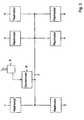
- FIG. 3 shows an arrangement of wheel modules (1, 2, 3, 4, 5, 6) and a central module (8), which to control the braking system of a three-axle vehicle, e.g. B. with a front axle and two rear axles, serves.
- the wheel modules (1, 2, 3, 4, 5, 6) are one below the other and with the central module (8) via the data bus system (7) connected.
- the wheel modules are all from same type, d. H. they have the one described in FIG. 1 Structure and that described in FIG. 2 Program structure.
- the central module (8) is with a Brake value transmitter (9) connected to the brake actuation emits a signal representing the driver. This signal is processed in the central module (8).
- the processing result is via the data bus system (7) the wheel modules (1, 2, 3, 4, 5, 6) as Brake value sent.
- the central module (8) preferably transmits the first time Commissioning of the brake system or the vehicle information about the wheel assignment of a wheel module to each of the wheel modules. This information is in a wheel module then in the non-volatile memory (23) saved and is continuously available from now on.
- the central module (8) and the brake value transmitter (9) can also be summarized in one unit.
- the brake value transmitter would be (9) via a suitable interface device directly connected to the data bus system (7).
- the brake value sent by the brake value transmitter then represents the driver's braking request.
- the determination the wheel assignment of the wheel modules in this case by using a diagnostic device that preferably also when commissioning the Brake system is connected to the data bus system (7), performed.
- the diagnostic tool is switched off after the Assignment procedure removed.
- the wheel modules (3, 4) are one Rear axle, e.g. B. the drive axle, the vehicle assigned.
- the wheel position parameters in the wheel modules (1, 2, 3, 4) are set such that the control signal of the control channel of the valve device (29) is supplied, the control channel number of the numbering of the corresponding wheel module according to FIG. 3.
- the control channel is in the wheel module (1) 1 defined as the main control channel in the wheel module (2)
- control channel 2 is main control channel and so on.
- the wheel modules (5, 6) are a further rear axle assigned to the vehicle.
- the wheel assignment of these wheel modules (5, 6) corresponds to the wheel modules (3, 4), which are also assigned to a rear axle been. Accordingly, in the wheel module (5) Control channel (3) has been defined as the main control channel, while in the wheel module (6) the control channel (4) is fixed has been. When using additional wheel modules these would depend on the type of vehicle axle which they are assigned a corresponding wheel assignment.
Landscapes
- Engineering & Computer Science (AREA)
- Transportation (AREA)
- Mechanical Engineering (AREA)
- Regulating Braking Force (AREA)
Applications Claiming Priority (2)
| Application Number | Priority Date | Filing Date | Title |
|---|---|---|---|
| DE19854788A DE19854788B4 (de) | 1998-11-27 | 1998-11-27 | Radmodul für ein Fahrzeug |
| DE19854788 | 1998-11-27 |
Publications (3)
| Publication Number | Publication Date |
|---|---|
| EP1006032A2 true EP1006032A2 (fr) | 2000-06-07 |
| EP1006032A3 EP1006032A3 (fr) | 2001-05-16 |
| EP1006032B1 EP1006032B1 (fr) | 2007-05-30 |
Family
ID=7889239
Family Applications (1)
| Application Number | Title | Priority Date | Filing Date |
|---|---|---|---|
| EP99118947A Expired - Lifetime EP1006032B1 (fr) | 1998-11-27 | 1999-09-25 | Module de roue pour une voiture |
Country Status (4)
| Country | Link |
|---|---|
| US (1) | US6216080B1 (fr) |
| EP (1) | EP1006032B1 (fr) |
| JP (1) | JP2000198431A (fr) |
| DE (2) | DE19854788B4 (fr) |
Families Citing this family (12)
| Publication number | Priority date | Publication date | Assignee | Title |
|---|---|---|---|---|
| DE10135600A1 (de) | 2001-07-20 | 2003-02-06 | Wabco Gmbh & Co Ohg | Antiblockiersystem |
| DE10161498A1 (de) * | 2001-12-14 | 2003-06-26 | Wabco Gmbh & Co Ohg | Magnetspuleneinheit |
| DE10203207B4 (de) * | 2002-01-21 | 2015-03-26 | Volkswagen Ag | Elektromechanische Bremsanlage |
| DE10221079B4 (de) | 2002-05-11 | 2011-01-20 | Wabco Gmbh | Antiblockiersystem für ein Radfahrzeug |
| US20050071070A1 (en) * | 2003-09-26 | 2005-03-31 | Peter Nilsson | Brake system with distributed electronic control units responsive to sensor input |
| DE102004059546A1 (de) | 2004-12-09 | 2006-06-22 | Lucas Automotive Gmbh | Elektronisches System zum Betreiben einer elektromechanischen Feststell-Bremsanlage |
| FR2880322B1 (fr) * | 2005-01-06 | 2007-08-17 | Haldex Brake Products Ltd | Reseau de commande electronique central pour des systemes de commande ou de regulation de la suspension et de la dynamique des vehicules sur les vehicules lourds |
| DE102007015995B4 (de) * | 2007-04-03 | 2015-10-08 | Zf Friedrichshafen Ag | Achsmodul für ein Fahrzeug |
| DE102007021646A1 (de) | 2007-05-09 | 2008-11-13 | Wabco Gmbh | Modulator |
| DE102007059688A1 (de) * | 2007-12-12 | 2009-06-25 | Lucas Automotive Gmbh | Aktuatoreinrichtung und Verfahren zum Ansteuern der Aktuatoreinrichtung |
| DE102008009522B4 (de) | 2008-02-16 | 2021-12-16 | Zf Cv Systems Hannover Gmbh | Verfahren zur Kalibrierung von Radgeschwindigkeiten |
| DE102023203549A1 (de) * | 2023-04-19 | 2024-10-24 | Continental Automotive Technologies GmbH | Elektromechanisch betreibbare Radbremse mit zentraler Ansteuerelektronik |
Citations (2)
| Publication number | Priority date | Publication date | Assignee | Title |
|---|---|---|---|---|
| DE2851107C2 (de) | 1978-11-25 | 1990-03-08 | Wabco Westinghouse Fahrzeugbremsen GmbH, 3000 Hannover | Schaltungsanordnung zur Verbesserung der Fahrstabilität von mit blockiergeschützten Bremsanlagen ausgerüsteten Fahrzeugen |
| EP0467112B1 (fr) | 1990-07-17 | 1994-12-28 | WABCO GmbH | Système de freinage électronique pour véhicules |
Family Cites Families (9)
| Publication number | Priority date | Publication date | Assignee | Title |
|---|---|---|---|---|
| DE4122484A1 (de) * | 1991-07-06 | 1993-01-07 | Teves Gmbh Alfred | Schaltungsanordnung zur erkennung von radsensordefekten |
| DE4135691C2 (de) | 1991-10-25 | 1998-04-16 | Aeg Westinghouse Transport | Anordnung zur Fahr- und Bremsregelung von Fahrzeugen, die mit mehreren Einzelrad-Antriebs- und Bremsmodulen ausgerüstet sind |
| US5288139A (en) * | 1992-06-05 | 1994-02-22 | Allied-Signal Inc. | Electropneumatic braking system |
| DE19521175C1 (de) * | 1995-06-10 | 1996-07-11 | Continental Ag | Elektrisch regelbares Bremssystem |
| JPH09207745A (ja) * | 1996-01-30 | 1997-08-12 | Nissan Motor Co Ltd | アンチスキッド制御装置 |
| DE19615203A1 (de) * | 1996-04-18 | 1997-10-23 | Bosch Gmbh Robert | Einrichtung zur Erkennung von elektromagnetischen Einstreuungen |
| DE19627731A1 (de) * | 1996-07-10 | 1998-01-15 | Abb Patent Gmbh | System für die Antriebs- und Bremsensteuerung eines Schienenfahrzeuges |
| DE19634567B4 (de) * | 1996-08-27 | 2007-11-29 | Robert Bosch Gmbh | Elektrisches Bremssystem |
| DE19713252A1 (de) * | 1997-03-29 | 1998-10-01 | Bosch Gmbh Robert | Verfahren und Vorrichtung zur Ermittlung einer die Fahrzeuggeschwindigkeit beschreibenden Größe |
-
1998
- 1998-11-27 DE DE19854788A patent/DE19854788B4/de not_active Expired - Lifetime
-
1999
- 1999-09-25 EP EP99118947A patent/EP1006032B1/fr not_active Expired - Lifetime
- 1999-09-25 DE DE59914357T patent/DE59914357D1/de not_active Expired - Lifetime
- 1999-11-24 JP JP11374544A patent/JP2000198431A/ja active Pending
- 1999-11-29 US US09/450,863 patent/US6216080B1/en not_active Expired - Lifetime
Patent Citations (2)
| Publication number | Priority date | Publication date | Assignee | Title |
|---|---|---|---|---|
| DE2851107C2 (de) | 1978-11-25 | 1990-03-08 | Wabco Westinghouse Fahrzeugbremsen GmbH, 3000 Hannover | Schaltungsanordnung zur Verbesserung der Fahrstabilität von mit blockiergeschützten Bremsanlagen ausgerüsteten Fahrzeugen |
| EP0467112B1 (fr) | 1990-07-17 | 1994-12-28 | WABCO GmbH | Système de freinage électronique pour véhicules |
Also Published As
| Publication number | Publication date |
|---|---|
| JP2000198431A (ja) | 2000-07-18 |
| DE19854788B4 (de) | 2009-12-03 |
| DE59914357D1 (de) | 2007-07-12 |
| EP1006032B1 (fr) | 2007-05-30 |
| US6216080B1 (en) | 2001-04-10 |
| EP1006032A3 (fr) | 2001-05-16 |
| DE19854788A1 (de) | 2000-05-31 |
Similar Documents
| Publication | Publication Date | Title |
|---|---|---|
| EP0481043B1 (fr) | Systeme de regulateurs connectes entre eux-memes pour vehicules a moteur | |
| EP0467112B2 (fr) | Système de freinage électronique pour véhicules | |
| DE19724092B4 (de) | Verfahren und Vorrichtung zur Ermittlung der Fahrzeugmasse | |
| DE4227083C2 (de) | Elektronisches Bremssystem, insbesondere für Straßenfahrzeuge | |
| EP0295396B1 (fr) | Système de freinage pour un véhicule dirigeable, à 2 ou plusieurs essieux, avec entraînement au moins sur les roues arrière | |
| EP0996558A1 (fr) | Procede et dispositif pour la stabilisation d'un vehicule | |
| WO2009152981A1 (fr) | Système de freinage et procédé de commande d'un frein de véhicule | |
| EP0949130B2 (fr) | Dispositif de commande d'un système de freinage de véhicule | |
| EP1006032B1 (fr) | Module de roue pour une voiture | |
| EP0189077B1 (fr) | Dispositif pour la commande de la pression de freinage | |
| EP0985586B1 (fr) | Système d'antiblocage pour un système de freinage électromécanique de véhicule basé sur un régulateur de logique floue | |
| EP1125067A1 (fr) | Procede et dispositif pour la surveillance du mouvement d'un actionneur | |
| DE19910048A1 (de) | Verfahren und Vorrichtung zur Überwachung der Bewegung eines Aktuators | |
| DE69722124T2 (de) | Verfahren zur Feststellung eines Auswechselzeitpunktes und Fahrzeugregelvorrichtung, die in der Lage ist, einen Auswechselzeitpunkt eines Betätigungsorgans anzuzeigen | |
| EP1254792B1 (fr) | Dispositif et procédé de commande de fonctions d'un véhicule | |
| EP1233893B1 (fr) | Procede et dispositif pour assurer la commande d'un systeme de freinage | |
| EP0927119A1 (fr) | Procede et dispositif pour determiner une grandeur representant la vitesse d'un vehicule | |
| EP0914998B1 (fr) | Méthode de mise en accord des forces de freinage de deux parties reliées formant un véhicule | |
| DE102019108620B4 (de) | Verfahren und Steuereinheit zum Steuern einer Lenkbremsfunktion für ein Fahrzeug und Bremssystem für ein Fahrzeug | |
| EP3500460B1 (fr) | Procédé de réglage des pressions de freinage, système de freinage d'un véhicule à moteur pour la mise en oeuvre de ce procédé et véhicule à moteur doté d'un tel système de freinage | |
| EP2213535B1 (fr) | Procédé de réglage ABS pour un véhicule et véhicule doté d'un système de freinage ABS | |
| EP1515881A1 (fr) | Procede et dispositif pour ajuster une deceleration longitudinale ou une acceleration longitudinale voulue | |
| EP0629533B1 (fr) | Procédé d'operation d'un système de freinage pour véhicule | |
| EP1171334B1 (fr) | Procede et dispositif de regulation de la force de freinage | |
| DE4121473A1 (de) | Einrichtung und verfahren zur antiblockier-steuerung fuer kraftfahrzeuge |
Legal Events
| Date | Code | Title | Description |
|---|---|---|---|
| PUAI | Public reference made under article 153(3) epc to a published international application that has entered the european phase |
Free format text: ORIGINAL CODE: 0009012 |
|
| AK | Designated contracting states |
Kind code of ref document: A2 Designated state(s): DE FR IT NL SE |
|
| AX | Request for extension of the european patent |
Free format text: AL;LT;LV;MK;RO;SI |
|
| PUAL | Search report despatched |
Free format text: ORIGINAL CODE: 0009013 |
|
| AK | Designated contracting states |
Kind code of ref document: A3 Designated state(s): AT BE CH CY DE DK ES FI FR GB GR IE IT LI LU MC NL PT SE |
|
| AX | Request for extension of the european patent |
Free format text: AL;LT;LV;MK;RO;SI |
|
| RIC1 | Information provided on ipc code assigned before grant |
Free format text: 7B 60T 8/00 A, 7B 60T 13/74 B |
|
| 17P | Request for examination filed |
Effective date: 20011116 |
|
| AKX | Designation fees paid |
Free format text: DE FR IT NL SE |
|
| GRAP | Despatch of communication of intention to grant a patent |
Free format text: ORIGINAL CODE: EPIDOSNIGR1 |
|
| RAP1 | Party data changed (applicant data changed or rights of an application transferred) |
Owner name: WABCO GMBH |
|
| GRAS | Grant fee paid |
Free format text: ORIGINAL CODE: EPIDOSNIGR3 |
|
| GRAA | (expected) grant |
Free format text: ORIGINAL CODE: 0009210 |
|
| AK | Designated contracting states |
Kind code of ref document: B1 Designated state(s): DE FR IT NL SE |
|
| REG | Reference to a national code |
Ref country code: SE Ref legal event code: TRGR |
|
| REF | Corresponds to: |
Ref document number: 59914357 Country of ref document: DE Date of ref document: 20070712 Kind code of ref document: P |
|
| ET | Fr: translation filed | ||
| PLBE | No opposition filed within time limit |
Free format text: ORIGINAL CODE: 0009261 |
|
| STAA | Information on the status of an ep patent application or granted ep patent |
Free format text: STATUS: NO OPPOSITION FILED WITHIN TIME LIMIT |
|
| 26N | No opposition filed |
Effective date: 20080303 |
|
| PGFP | Annual fee paid to national office [announced via postgrant information from national office to epo] |
Ref country code: DE Payment date: 20140930 Year of fee payment: 16 Ref country code: NL Payment date: 20140829 Year of fee payment: 16 |
|
| PGFP | Annual fee paid to national office [announced via postgrant information from national office to epo] |
Ref country code: SE Payment date: 20140918 Year of fee payment: 16 |
|
| PGFP | Annual fee paid to national office [announced via postgrant information from national office to epo] |
Ref country code: IT Payment date: 20140915 Year of fee payment: 16 |
|
| PGFP | Annual fee paid to national office [announced via postgrant information from national office to epo] |
Ref country code: FR Payment date: 20140926 Year of fee payment: 16 |
|
| REG | Reference to a national code |
Ref country code: DE Ref legal event code: R119 Ref document number: 59914357 Country of ref document: DE |
|
| PG25 | Lapsed in a contracting state [announced via postgrant information from national office to epo] |
Ref country code: IT Free format text: LAPSE BECAUSE OF NON-PAYMENT OF DUE FEES Effective date: 20150925 |
|
| REG | Reference to a national code |
Ref country code: SE Ref legal event code: EUG |
|
| PG25 | Lapsed in a contracting state [announced via postgrant information from national office to epo] |
Ref country code: SE Free format text: LAPSE BECAUSE OF NON-PAYMENT OF DUE FEES Effective date: 20150926 |
|
| REG | Reference to a national code |
Ref country code: NL Ref legal event code: MM Effective date: 20151001 |
|
| REG | Reference to a national code |
Ref country code: FR Ref legal event code: ST Effective date: 20160531 |
|
| PG25 | Lapsed in a contracting state [announced via postgrant information from national office to epo] |
Ref country code: DE Free format text: LAPSE BECAUSE OF NON-PAYMENT OF DUE FEES Effective date: 20160401 |
|
| PG25 | Lapsed in a contracting state [announced via postgrant information from national office to epo] |
Ref country code: FR Free format text: LAPSE BECAUSE OF NON-PAYMENT OF DUE FEES Effective date: 20150930 Ref country code: NL Free format text: LAPSE BECAUSE OF NON-PAYMENT OF DUE FEES Effective date: 20151001 |