EP1006286A2 - Dispositif de charnière - Google Patents
Dispositif de charnière Download PDFInfo
- Publication number
- EP1006286A2 EP1006286A2 EP99305750A EP99305750A EP1006286A2 EP 1006286 A2 EP1006286 A2 EP 1006286A2 EP 99305750 A EP99305750 A EP 99305750A EP 99305750 A EP99305750 A EP 99305750A EP 1006286 A2 EP1006286 A2 EP 1006286A2
- Authority
- EP
- European Patent Office
- Prior art keywords
- cam
- base
- hinge device
- casing
- projection
- Prior art date
- Legal status (The legal status is an assumption and is not a legal conclusion. Google has not performed a legal analysis and makes no representation as to the accuracy of the status listed.)
- Granted
Links
Images





Classifications
-
- H—ELECTRICITY
- H04—ELECTRIC COMMUNICATION TECHNIQUE
- H04B—TRANSMISSION
- H04B1/00—Details of transmission systems, not covered by a single one of groups H04B3/00 - H04B13/00; Details of transmission systems not characterised by the medium used for transmission
- H04B1/38—Transceivers, i.e. devices in which transmitter and receiver form a structural unit and in which at least one part is used for functions of transmitting and receiving
-
- H—ELECTRICITY
- H04—ELECTRIC COMMUNICATION TECHNIQUE
- H04M—TELEPHONIC COMMUNICATION
- H04M1/00—Substation equipment, e.g. for use by subscribers
- H04M1/02—Constructional features of telephone sets
- H04M1/0202—Portable telephone sets, e.g. cordless phones, mobile phones or bar type handsets
- H04M1/0206—Portable telephones comprising a plurality of mechanically joined movable body parts, e.g. hinged housings
- H04M1/0208—Portable telephones comprising a plurality of mechanically joined movable body parts, e.g. hinged housings characterized by the relative motions of the body parts
- H04M1/0214—Foldable telephones, i.e. with body parts pivoting to an open position around an axis parallel to the plane they define in closed position
- H04M1/0216—Foldable in one direction, i.e. using a one degree of freedom hinge
-
- F—MECHANICAL ENGINEERING; LIGHTING; HEATING; WEAPONS; BLASTING
- F16—ENGINEERING ELEMENTS AND UNITS; GENERAL MEASURES FOR PRODUCING AND MAINTAINING EFFECTIVE FUNCTIONING OF MACHINES OR INSTALLATIONS; THERMAL INSULATION IN GENERAL
- F16C—SHAFTS; FLEXIBLE SHAFTS; ELEMENTS OR CRANKSHAFT MECHANISMS; ROTARY BODIES OTHER THAN GEARING ELEMENTS; BEARINGS
- F16C11/00—Pivots; Pivotal connections
- F16C11/02—Trunnions; Crank-pins
-
- G—PHYSICS
- G06—COMPUTING OR CALCULATING; COUNTING
- G06F—ELECTRIC DIGITAL DATA PROCESSING
- G06F1/00—Details not covered by groups G06F3/00 - G06F13/00 and G06F21/00
- G06F1/16—Constructional details or arrangements
- G06F1/1613—Constructional details or arrangements for portable computers
- G06F1/1615—Constructional details or arrangements for portable computers with several enclosures having relative motions, each enclosure supporting at least one I/O or computing function
- G06F1/1616—Constructional details or arrangements for portable computers with several enclosures having relative motions, each enclosure supporting at least one I/O or computing function with folding flat displays, e.g. laptop computers or notebooks having a clamshell configuration, with body parts pivoting to an open position around an axis parallel to the plane they define in closed position
-
- G—PHYSICS
- G06—COMPUTING OR CALCULATING; COUNTING
- G06F—ELECTRIC DIGITAL DATA PROCESSING
- G06F1/00—Details not covered by groups G06F3/00 - G06F13/00 and G06F21/00
- G06F1/16—Constructional details or arrangements
- G06F1/1613—Constructional details or arrangements for portable computers
- G06F1/1633—Constructional details or arrangements of portable computers not specific to the type of enclosures covered by groups G06F1/1615 - G06F1/1626
- G06F1/1662—Details related to the integrated keyboard
- G06F1/1669—Detachable keyboards
-
- G—PHYSICS
- G06—COMPUTING OR CALCULATING; COUNTING
- G06F—ELECTRIC DIGITAL DATA PROCESSING
- G06F1/00—Details not covered by groups G06F3/00 - G06F13/00 and G06F21/00
- G06F1/16—Constructional details or arrangements
- G06F1/1613—Constructional details or arrangements for portable computers
- G06F1/1633—Constructional details or arrangements of portable computers not specific to the type of enclosures covered by groups G06F1/1615 - G06F1/1626
- G06F1/1675—Miscellaneous details related to the relative movement between the different enclosures or enclosure parts
- G06F1/1679—Miscellaneous details related to the relative movement between the different enclosures or enclosure parts for locking or maintaining the movable parts of the enclosure in a fixed position, e.g. latching mechanism at the edge of the display in a laptop or for the screen protective cover of a PDA
-
- G—PHYSICS
- G06—COMPUTING OR CALCULATING; COUNTING
- G06F—ELECTRIC DIGITAL DATA PROCESSING
- G06F1/00—Details not covered by groups G06F3/00 - G06F13/00 and G06F21/00
- G06F1/16—Constructional details or arrangements
- G06F1/1613—Constructional details or arrangements for portable computers
- G06F1/1633—Constructional details or arrangements of portable computers not specific to the type of enclosures covered by groups G06F1/1615 - G06F1/1626
- G06F1/1675—Miscellaneous details related to the relative movement between the different enclosures or enclosure parts
- G06F1/1681—Details related solely to hinges
-
- G—PHYSICS
- G06—COMPUTING OR CALCULATING; COUNTING
- G06F—ELECTRIC DIGITAL DATA PROCESSING
- G06F1/00—Details not covered by groups G06F3/00 - G06F13/00 and G06F21/00
- G06F1/16—Constructional details or arrangements
- G06F1/1613—Constructional details or arrangements for portable computers
- G06F1/1633—Constructional details or arrangements of portable computers not specific to the type of enclosures covered by groups G06F1/1615 - G06F1/1626
- G06F1/1675—Miscellaneous details related to the relative movement between the different enclosures or enclosure parts
- G06F1/1683—Miscellaneous details related to the relative movement between the different enclosures or enclosure parts for the transmission of signal or power between the different housings, e.g. details of wired or wireless communication, passage of cabling
-
- E—FIXED CONSTRUCTIONS
- E05—LOCKS; KEYS; WINDOW OR DOOR FITTINGS; SAFES
- E05D—HINGES OR SUSPENSION DEVICES FOR DOORS, WINDOWS OR WINGS
- E05D11/00—Additional features or accessories of hinges
- E05D11/10—Devices for preventing movement between relatively-movable hinge parts
- E05D11/1028—Devices for preventing movement between relatively-movable hinge parts for maintaining the hinge in two or more positions, e.g. intermediate or fully open
- E05D11/105—Devices for preventing movement between relatively-movable hinge parts for maintaining the hinge in two or more positions, e.g. intermediate or fully open the maintaining means acting perpendicularly to the pivot axis
-
- E—FIXED CONSTRUCTIONS
- E05—LOCKS; KEYS; WINDOW OR DOOR FITTINGS; SAFES
- E05Y—INDEXING SCHEME ASSOCIATED WITH SUBCLASSES E05D AND E05F, RELATING TO CONSTRUCTION ELEMENTS, ELECTRIC CONTROL, POWER SUPPLY, POWER SIGNAL OR TRANSMISSION, USER INTERFACES, MOUNTING OR COUPLING, DETAILS, ACCESSORIES, AUXILIARY OPERATIONS NOT OTHERWISE PROVIDED FOR, APPLICATION THEREOF
- E05Y2999/00—Subject-matter not otherwise provided for in this subclass
Definitions
- This invention relates to a hinge device, and in particular, to a hinge device for a portable electronic device.
- flip-type electronic device Various types of compact electronic devices such as cellular telephones, portable computers (with or without a communication function), electronic note-books, and game computers have come into general use with advances in electronics technology in recent years. These compact devices have flip members (hereinafter referred to as flip-type electronic device), which can be closed when the device is carried, and can be open to a specific size to make the device easy to operate when the device is in use.
- a cellular telephone has a flip member which can be opened and closed. Recently, a detachable flip member has become in wide demand.
- the flip member is attached to the device main body by means of a hinge device.
- the conventional hinge device becomes complicated and large because it must includes a mechanism to maintain the flip member at a predetermined angle when the flip member is opened and closed.
- the hinge device must be simplified, and as the result, the flip member cannot be securely held at the predetermined angle.
- electrical connections between the device main body and the flip member cannot be established in a small limited space.
- the hinge device comprises: a casing having a projection hole; a cam provided in the casing, the cam being rotatable with respect to a rotational axis, movable in the direction of the rotational axis, and undetachable from the casing, the cam having a projection projecting through the projection hole and a cam face surrounding the rotational axis; a flat spring for holding the cam face; a base movable in the direction of the rotational axis, the cam being rotatably attached to the base; and a pressing spring for urging the cam and the base toward the direction of the projection.
- One of the cam and the base has a rotation stopper, and the other has a concavity for receiving the rotation stopper.
- the rotation stopper when the rotation stopper is engaged with the concavity, the rotation is inhibited, preventing slippage of the shaft from a predetermined angle due to a shock.
- This is advantageous when the hinge device is applied to a flip-type portable phone with a flip member, because the present invention increases the holding force for maintaining the flip member opened at a predetermined angle.
- the rotation stopper engaged with the concavity can be released by rotating the cam relative to the base so that the base is pushed against the biasing force by the pressing spring toward the rear.
- the hinge device of the present invention further comprises a engaging mechanism for engaging the base with the casing to prevent rotation of the base relative to the casing.
- the engaging mechanism prevents the base from being rotated relative to the casing and limits the movement of the base so that the base cannot further move to the front.
- the pressing spring urges the base toward the front, the base cannot further move to the front. Therefore, the biasing force toward the front does not act on the cam which is positioned in front of the base. That is, the cam is not pressed onto the casing, thereby preventing occurrence of friction between the cam and the casing.
- the engaging mechanism comprises a slit made in the casing, and a projection formed on the base, and the projection is inserted through the slit.
- the engaging mechanism of the slit in the casing and the projection of said base simplifies the structure of the hinge device, can be easily manufactured, and can be easily positioned when assembled.
- a pair of the flat springs having L-shapes are provided.
- the ends of the flat springs are fixed to the base, while the other ends of the flat springs are in contact with the cam face, and the two flat springs are positioned opposite to each other on both sides of the cam.
- the pressing spring is in contact with the flat springs so that the pressing force is converted by way of the flat spring into a force to close the flat springs.
- the flat spring may have a U-shape, a middle portion of the flat spring is fixed to the base, and both ends of the flat spring are in contact with the cam face.
- the pressing spring is in contact with the flat springs so that the pressing force is converted by way of said flat spring into a force to close said flat springs.
- the closing force of the flat spring is increased.
- the increased closing force produces a large torque on the cam faces.
- the hinge device of the present invention is small, it can produce a torque on the cam faces to make the operation of the flip member stable.
- the cam has a shaft hole extending on the rotational axis, and the base has a shaft inserted in the shaft hole so that the cam is rotatable relative to the base.
- the base supports the rotatable cam, and makes the rotation of the cam stable, preventing misalignment of the cam.
- the casing has a slit and a stopper face at one end of the slit
- the base has a main base which is inserted through the slit and which is movable in the slit.
- the slit is engaged with the base, preventing the rotation of the base relative to the casing. Therefore, the cam can be rotated relative to the casing, and the rotation of the cam becomes more stable. Further, this engaging mechanism is quite simple, thereby simplifying the manufacturing and assembly process of the hinge device.
- the flat spring has a claw inserted in the slit.
- the flat spring is engaged with the slit so that the rotation of the flat spring relative to the casing is inhibited. Therefore, the flat spring can hold the cam securely at a predetermined position.
- the flat spring has a claw, and the base may have a concavity for engaging with the claw. Only the base is in contact with the slit while the flat spring is not in contact with the slit. The rotation of the flat spring relative to the casing is still inhibited.
- the base is made of a material (for example, plastic) easy to slip along the casing, the cam can be smoothly moved forward and backward (in the direction of the rotational axis).
- a through-hole may be made through the base and the cam. Through this through-hole, electrical connections between the flip member and the device main body can be established.
- the hinge device is simplified, can hold the flip member securely, and can reduce the size. Further, this invention makes the manufacturing and assembling process easy, and enhances the durability and reliability of the hinge device. In addition, this invention maintains the detachable mechanism and the mechanism for establishing electrical connections.
- FIGS 1A and 1B show the first embodiment.
- the hinge device 10 comprises a casing 11, a cam 12, an engaging portion 13, a projection 14, a shaft base (or bearing) 15, a flat spring (plate spring) 16, and a pressing spring 17.
- the casing 11 is an approximately rectangular hollow case.
- a projection hole 11a is made in the front side of the casing 12, and stopper slits 11b are made in both sides of the casing 11.
- the casing 11 includes the cam 12 which has a cam face surrounding the rotational axis.
- the cam 12 has the shape, for example, shown in Figure 2.
- the cam 12 is axially symmetrical with respect to the rotational axis O.
- the cam face is composed of holding faces 12a and restoring force receiving faces 12b.
- the flip member When the flip member is closed on the main body, the flip member is positioned at position C. In this situation, the flat spring 16 holds the restoring force receiving faces 12b. The restring force receiving faces 12b are positioned inside a virtual circumference D having the center corresponding to the rotational axis O. Therefore, a torque to close the flip member acts on the flat spring 16 so that the flip is biased toward the closed position.
- the flip member When the flip member is opened from the closed position, that is, when the flat spring 16 is rotated clockwise, the flip member passes position B and quickly (automatically) moves to the opened position.
- the flat spring 16 seems to be rotated, the cam 12 is in fact rotated. That is, one of the cam 12 and the flat spring 16 may be relatively rotated with respect to the other.
- the rotation angle ⁇ is set to, for example, 30 degrees.
- the cam 12 has a rotation stopper 12c which projects to the rear to stop the rotation, as shown in Figure 1.
- the rotation stopper 12c has a triangular cross-section and extends in the direction perpendicular to the rotational axis O.
- a stopper 13 wider than the projection 11a is integrally formed on or coupled to the front portion of the cam 12.
- the projection 14 is integrally formed with or coupled to the front portion of the stopper 13, and projects through the projection holes 11a.
- the projection 14 has a rectangular cross-section to prevent slipping.
- the projection 14 has thread ribs 14a extending in the direction corresponding to the rotational axis. While the shapes, number, and positions of the thread ribs 14a may be appropriately determined, this embodiment has two thread ribs at each corner, that is, eight thread ribs in total at the corners.
- the thread ribs 14a are tightly fit in the hole, thereby enhancing the connection strength.
- the edges of the projection 14 may be round.
- the shaft base 15 is positioned at the back of the cam 12 within the casing 11.
- the shaft base 15 has a concavity 15a which receives the rotation stopper 12c.
- the shaft base 15 has two engaging projections 15b inserted through the engaging slits 11b in both sides of the casing 11.
- the engaging projections 15b slightly project from the sides of the casing 11 through the engaging slits 11b, preventing the shaft base 15 from being rotated relative to the casing 11 and limiting the movement of shaft base 15 so that the shaft base 15 cannot further move to the front. While the engaging projections 15b are engaged with the engaging slits 11b, the shaft base 15 can be freely moved toward the rear.
- the engaging projections 15b do not necessarily project from the sides of the casing 11, and the ends of the engaging projections 15b may correspond to the sides of the casing 11 to make the sides flat.
- the shapes of the projection 14, the cam 12, and the shaft base 15 can be clearly understood from the perspective view of Figure 4.
- the thread ribs 14 are omitted, and the holder faces 12a is not concave but flat, as one example.
- the shaft base 15 has a shaft 15c corresponding to the rotational axis O.
- the cam 12 has a through-hole 12d through which the shaft 15c is inserted.
- the shaft 15c and the through-hole 12d support the smooth rotation of the cam 12 relative to the shaft base 15 with respect to the rotational axis O, preventing misalignment of the shaft 15c.
- an elastic hook 19 whose diameter is greater than the shaft 15c is formed.
- a slit is made in the tip of the elastic hook 19, which can be elastically narrowed.
- the hook 19 is elastically deformed. After the hook 19 has been inserted to the maximum depth, the hook 19 is caught by a step (not shown) inside the through-hole 12d.
- the flat spring 16 has a U-shape providing a biasing force to close the flat spring, and is positioned at the back of the shaft base 15. Free ends of the flat spring 16 press the cam face (the holder faces 12a or the restoring force receiving faces 12b) from the direction perpendicular to the rotational axis O. Thus, the flat spring 16 produces the torque depending on the shape of the cam face in contact with the free ends of the flat spring 16.
- the pressing spring 17 is positioned at the back of the cam 12 within the casing 11.
- the hinge device 10 has the rotation stopper 12c on the cam 12 and the concavity 15a in the shaft base 15.
- resistance is caused that inhibits the rotation of the cam 12 relative to the shaft base 15. This prevents slippage of the shaft from a predetermined angle due to a shock (shown in Figure 6A).
- the rotation stopper 12c engaged with the concavity 12a can be released when the cam 12 is rotated relative to the shaft base 15 so that the shaft base 15 is pushed against the biasing force by the pressing spring 17 toward the rear, as indicated by the arrow D.
- the force to release the rotation stopper 12c may be adjusted by changing the angle of its triangular shape.
- the rotation stopper 12c may employ another shape to adjust the force to release the rotation stopper 12c.
- the engaging projections 15b of the shaft base 15 are engaged with the engaging slits 11b of the casing 11 to limit the movement of the shaft base 15 so that the shaft base 15 cannot move further to the front. Therefore, the biasing force by the pressing spring 17 does not act on the cam 12 in front of the shaft base 15. That is, the cam 12 is not biased to the front by the pressing spring 17. Therefore, the cam 12 is not pressed onto the casing 11, preventing occurrence of friction between the cam 12 and the casing 11.
- the hinge device 10 is detachable when retracting the projection 14.
- the flip member 20 has a flip body 21 and attachments 22.
- the attachments 22 project from and are integrally formed with both corners of the flip body 21. Approximately rectangular mounting holes 22 are made in the attachments 22. The mounting holes 22a are slightly smaller than the casing 11 of the hinge device 10.
- the hinge devices 10 are inserted in the mounting holes 22 and are fixed to the flip member 20.
- the hinge devices 10 are tightly fit in the mounting holes 22a because the hinge devices 10 are forcibly inserted into the slightly smaller mounting holes 22.
- the size of the flip member 20 can be reduced. Particularly, because the hinge device 10 is small in diameter, the flip member 20 becomes thin.
- a portable phone with the flip member 20 will be explained.
- the portable phone 30 has an attachment 31 at its edge.
- the attachment 31 comprises concavities 32 and a center expanding portion 33, and is complementary to the attachments 22 of the flip member 22.
- Mounting holes 33a are made in both ends of the center expanding portion 33.
- the shape and size of the mounting holes 33a are determined depending on the projection 14 of the hinge devices 10.
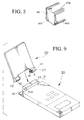
- FIG 9 shows a process for mounting the flip member 20 to the portable phone 30.
- the hinge devices 10 are fixed to the attachments 22 of the flip member 20 so that the projections 14 project inwardly.
- the detachable mechanism of the hinge device 10 that is, by retracting the projections 14 in the direction indicated by the arrow E, the flip member 20 can be mounted to the portable phone 30, and then the biasing force due to the pressing spring 17 urges and restores the projections 14 to connect the flip member 20 to the portable phone 30.
- the flip member 20 may be detached only in the manufacturing and maintenance process. Alternatively, the user may detach the flip member 20 at will.
- the rotation stopper 12c is engaged with the concavity 15a.
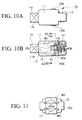
- Figures 10A and 10B show the second embodiment of the present invention. Except for two modified flat springs, the second embodiment is identical to the first embodiment.
- the two flat springs 40 have an L-shape. Base ends of the two flat springs 40 are fixed to points 40a on the shaft base 15, and the other free ends of the flat springs 40 are in contact with points 40b on the cam face from the direction perpendicular to the rotational axis O, so that the two flat springs 40 face each other, that is, are positioned opposite to each other. Bent portions 40c of the flat springs 40 are movable and are positioned at the back of the fixed portions 40a.
- the pressing spring 17 is in contact with the flat spring 40 at points radially outside the fixed portions 40a, and biases the flat springs 40 toward the front along the rotational axis.
- the pressing force F toward the front by the pressing spring 17 is converted into the force G to urge the flat springs 40 inwardly (closing force) by way of the fixed portions 40a as the fulcrums.
- the flat springs 16 hold the cam faces of the cam 12 from the direction perpendicular to the rotational axis O.
- the flat springs 40 produce a torque depending on the shapes of the cam faces in contact with the free ends of the flat springs 40.
- the pressing spring 17, the points of action 40d (functioning as the power points in the leverage operation) of the pressing force by the pressing spring 17, the fixed portions 40a (functioning as the fulcrums in the leverage operation), and the contact portions 40b (functioning the points of action in the leverage operation) constitute a conversion mechanism for converting the pressing force by the pressing spring 17 into the closing force of the flat springs 40.
- the hinge device 10 converts the pressing force F by the pressing spring 17 into the closing force G of the flat springs 40 by way of the fixed portions 40a as the fulcrums. Accordingly, by increasing the pressing force by the pressing spring 17, the closing force by the flat springs 40 can be easily increased. The increased closing force produces a large torque on the cam face. Although the hinge device of the present invention is small, it can produce a large torque on the cam face that makes the operation of the flip member stable.
- Figure 13 shows the third embodiment of the present invention. Except for the arrangement of the flat spring, the other structure of the third embodiment, which includes the shape of the flat spring, is identical to that of the first embodiment.
- the middle portion 50a of the flat spring 50 is fixed to the shaft base 15. It should be noted that bent portions 50b of the flat spring 50 are movable and are positioned at the back of the fixed portion 50a.
- the flat spring 50 has an inherent closing force.
- the additional closing force converted from the pressing force by the pressing spring 17 also acts on the cam faces as the holding force. Therefore, although the hinge device of the present invention is small, it can produce a large torque on the cam faces.
- the present invention is not limited to the above embodiments, and may employ the following structures:
- Figures 14A to 14C show the fourth embodiment.
- Figure 14A is a top view
- Figure 14B is a side view
- Figure 14C is a front view of the hinge device.
- the hinge device 110 comprises a casing 112, a cam 113, a shaft 114, a flat spring (plate spring) 115, and a pressing spring 116.
- Figures 16A to 16C show the flat spring 115 in the embodiment, and Figure 17 shows the cam 113 and the shaft 114.
- the casing 112 includes the cam 113, the shaft base 114, the flat spring 115, and the pressing spring 116.
- the casing 112 is an approximately rectangular hollow case.
- a projection hole 121 is made in the side (front side) of the casing 112 from which a part of the cam 113 projects. From the opposite side to the projection side, stopper plates 122 project and hold the rear end of the pressing spring 116, which is thereby prevented from falling off.
- stopper slits 123 are made for holding stopper projections 143 of the shaft base 114 and claws 153 of the flat spring 115, which are movable in the direction of the rotational axis O.
- the stopper slits 123 have stopper faces 124 at their front ends, and are vacant from the stopper faces 124 to the rear side. The movement of the shaft base 114 and the flat spring 115 are limited by the stopper faces 124 so that they cannot move further to the front.
- the cam 113 comprises a cam face 131, a flange 132, and a projection 133, which are coupled together (or integrally formed) and are rotatable with respect to the rotational axis O.
- the cam 113 has a through-hole 134 corresponding to the rotational axis O.
- the cam face 131 surrounds the rotational axis O.
- Figure 15 shows a cross-section at the cam face 131.
- the cam face 131 is axially symmetrical at the cross-section perpendicular to the rotational axis O.
- the cam face 131 has holder faces 131a and restoring force receiving faces 131b.
- the holder faces 131a and the restoring force receiving faces 131b are held by the flat spring 115 from the direction perpendicular to the rotational axis O.
- a rotatable flip member for example, a screen containing section of a laptop computer or a cover of portable phone
- the flip member is positioned at a position A.
- the flat spring 115 holds the holder faces 131a so that the flip member is stably held at an opening angle ⁇ (for example, 120 degrees) from the device main body.
- the flip member When the flip member is closed on the device main body, the flip member is positioned at a position C. In this situation, the flat spring 115 holds the restoring force receiving faces 131b. The restoring force receiving faces 131b are positioned and inclined inwardly from a virtual circumference D. Therefore, a rotational torque to close the flip member occurs on the cam face 131 so that the flip member is biased toward the closed position.
- the flip member When the flip member is opened from the closed position, that is, when the flat spring 115 is rotated in the anti-clockwise direction in Figure 15 (the cam face 131 is in fact rotated), the flip member passes the position B, then quickly moves to the open position A.
- the angle ⁇ between the positions A and B is, for example, 60 degrees.
- the flange 132 has an approximately disc shape, and is coupled and fixed to the front side of the cam face 131.
- the flange 132 has a diameter greater than that of the projection hole 121, so that the projection 133 projects through the projection hole 121 from the casing 112 while the cam face 132 remains within the casing 112. Therefore, the cam 113 cannot be pulled out from the casing 112.
- the projection 133 is integrally formed with (or is coupled and fixed to) the front side of the flange 132.
- the projection 133 projects through the projection hole 121, and has a rectangular column shape to prevent its rotation when the projection 133 fits in a hole in the main device.
- the projection 133 has ribs 133a extending in the direction of the rotational axis as shown in Figure 14C (but omitted in Figure 17).
- the shapes, numbers, and positions of the ribs 133a may be appropriately determined, and in the embodiment, there are two ribs 133a on the opposite sides.
- the ribs 133a enhance the degree of fitness of the projection 133 when the projection 133 is inserted into the corresponding hole.
- the shaft base 114 comprises a main base 141, and a shaft 142 protruding toward the front.
- the shaft base 114 is arranged in the casing 112 so that the main base 141 is positioned in the rear side opposite to the cam 113.
- the shaft 142 is inserted through the through-hole 134 of the cam 113 so that the cam 113 is rotatable.
- the main base 141 can move forward and backward within the casing 112 while guides 141a at both edges of the main base 141 are in contact with the inner surfaces of the casing 112.
- the guides 141a allows the shaft 142 to stably move forward and backward along the rotational axis O, preventing misalignment of the shaft 142.
- the main base 141 has the stopper projections 143 which are to be inserted through the stopper slits 123 of the casing 112.
- the stopper projections 143 projects slightly through the stopper slits 123, inhibits the rotation of the shaft 114 relative to the casing 112, and allows the shaft 114 to move forward and backward behind the stopper faces 124.
- the main base 141 defines spaces 144 through which the flat spring 115 extends from the backside of the main base 141 to the front.
- the main base 141 has engagers 145 engaged with the claws 153 of the flat spring 115 to prevent the rotation of the flat spring 115 relative to the shaft base 114.
- a projection 146 engaged with an engaging hole 154 of the flat spring 115 is made.
- the shaft 142 is cylinder, and is inserted through the through-hole 134 of the cam 113 so that the cam 113 can rotate around the rotational axis O.
- the shaft base 114 has a through-hole 147 corresponding to the rotational axis O through the shaft 142, the main base 141, and the projection 146. Through this through-hole 147 of the shaft base 141, electrical connections between the parts can be established.
- the projection 146 separates the connections from the flat spring 115, thereby reducing the danger of a short-circuit.
- the flat spring 115 has a U-shape providing a biasing force in the direction to close the flat spring 115.
- the flat spring 115 has a fixed portion 151 and free ends 152.
- the fixed portion 151 is arranged on the back side of the shaft base 114, and the free ends 152 extend through the spaces 144 adjacent to the shaft base 114 to the front.
- the claws 153 project, corresponding to the engagers 145 of the shaft base 114.
- the claws 153 are engaged with the engaging slits 123 of the casing 112 and with the engagers 145. Therefore, the flat spring 114 can move forward and backward together with the shaft base 114, while the rotation of the flat spring relative to the casing 112 and the shaft base 114 is inhibited.
- a hole 154 is made in the fixed portion. The projection 146 of the shaft base 114 is inserted through the hole 154 so that the through-hole 147 extends through the engaging hole 154.
- the free ends 152 extend to the cam face 131 of the cam 113, and hold both sides of the cam face 131 (the holder faces 131a, or the restoring force receiving faces 131b) from the direction perpendicular to the rotational axis O.
- the free ends 152 generate a torque depending on the shapes of the contact portions of the cam face 131
- extended rising portions (beads) 115a rising from the surface of the plate extend between the free ends 152 through the fixed portion 151.
- the extended rising portions 115a enhance the flexural strength of the flat spring 115, and enhance the durability of the hinge device 110.
- the flat spring 115 comprises a plurality of plates to hold the cam 113 tightly.
- three plates are layered as the flat spring 115.
- the pressing spring 116 is a coil spring, and is located at the rear side of the flat spring 115 to bias the cam 113, the shaft base 114, and the flat spring 115 toward the front. The rear end of the pressing spring 116 is held by the engaging plates 122 of the casing 112.
- the pressing spring 116 biases the cam 113 and the shaft base 114.
- the projection 133 can be retracted into the casing 112. Therefore, when the hinge device 110 is applied to a flip type portable electronic device with the flip member, a flip member can be detachable.
- the shaft base 114 and the flat spring 115 are engaged with the engaging slits 123, and cannot be rotated relative to the casing 112. Therefore, the cam 113 can be stably rotated relative to the casing 112, preventing misalignment of the cam 113 from the rotational axis. Further, this mechanism is simple, makes the manufacturing and assembling process of the device easy, reduces the size of the hinge device, and simplifies the entire construction of the hinge device.
- the through-hole 147 extends through the shaft base 114 and the flat spring 115, the electrical connections can be established through the hinge device.
- the hinge device When the hinge device is applied to a flip type portable electronic device, the device and the top are electrically connected, reducing the danger of a short-circuit.
- the hinge device 110 of the fifth embodiment is comparatively compact, and is not equipped with the means to establish the electrical connections.
- the same reference numbers are employed to designate like parts in the fourth embodiment, a detailed description thereof is omitted, and only the differences will be discussed.
- the difference between the fourth and fifth embodiments is that the flat spring 115 does not come in contact with the engaging slits 123 of the casing 112. Only the structure of the shaft base 114 and the flat spring 115 differs from those in the fourth embodiment.
- Figures 18A and 18B show the flat spring 115 of the fifth embodiment
- Figure 19 shows the shaft base 114 and the cam 113 of the fifth embodiment.
- the shaft base 114 defines engaging concavities 148 in the rear side of the stopper projections 143.
- an elastic hook 149 whose diameter is greater than the shaft 142 is formed.
- a slit is made in the tip of the elastic hook 149 so that the hook 146 can be elastically narrowed.
- the hook 149 is elastically deformed so as to pass through the cam 113. After the hook 149 has been inserted to the maximum depth, the hook 149 is caught by a step (not shown) inside the through-hole 134.
- the hinge device of the fifth embodiment has no through-hole because the device does not provide electrical connections.
- the flat spring 115 has claws 153b smaller than the claws 153 in the fourth embodiment, and has no engaging hole because the device does not provide electrical connections.
- the claws 153b are engaged with the engaging concavities 148.
- the flat spring 115 is thus attached to the shaft base 114, is movable forward and backward without contact with the engaging slits 123 of the casing 112, and is prevented from being rotated relative to the casing 112 and the shaft base 114.
- the shaft base 114 is in contact with the engaging slits 123 while the flat spring 115 is not in contact with the engaging slits 123, and the rotation of the flat spring 115 relative to the casing 112 is inhibited.
- the shaft base 114 is made from a material (for example, plastic) easy to slip on the casing 112
- the cam 113 can smoothly move forward and backward. Therefore, by means of the hinge device 110, the flip member can be easily and smoothly attached to and detached from the main body of the portable electronic device, while maintaining the rotational stability of the cam 113.
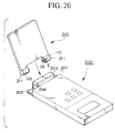
- a flip member 210 is detachably and rotatably attached to a phone main body 200.
- a connector 201 for connecting the flip member 210 is provided at the main body 200, and has concavities 202 and a rising section 203.
- the shapes of the concavities 202 and the rising section 203 are complementarily shaped relative to a connector 211 of the flip member 210.
- mounting holes 204 are made.
- the projections 133 of the hinge device 110 of the flip member are tightly inserted.
- the shape and size of the mounting holes 204 is complementary to the projections 133.
- the flip member 210 has two attachments 211.
- the attachments 211 are integrally formed with and project from both lower edges of the flip member 210.
- the attachments 211 include the hinge devices 10, which connect the flip member 210 rotatably and detachably to the phone main body 200.
- the projections 133 of the hinge device 110 are retracted (drawn back in the casing 112 by pressing the projection 133 in the direction E). Then, the attachments 211 are placed in the concavities 202 to make the projections 133 correspond to the mounting holes 204. While the projections 133 are biased toward the mounting holes 204 by the pressing springs 116, the projections 133 automatically project and are tightly fit in the mounting holes 204 when the pressing force toward the direction E disappears. Thus, the connection between the phone main body 200 and the flip member 210 is completed.
- a wiring part (such as a probe pin) in the through-hole 147 of the hinge device 110 may be in contact with a contact in the mounting hole 204.
- a mechanism for urging the projection 133 in the direction opposite to the direction E may be provided in the mounting hole 204.
- the flip member 210 may be detached and attached only in the manufacturing and maintenance process, and the detachable system may be unrecognized by a user.
- the user may detach the flip member 2.0 at will.
- the present invention is not limited to these embodiments.
- the shapes of the cam and the flat spring can be modified.
- the shapes and structures of the casing and the projections can be modified depending on a purpose and use of a device to which the present invention is applied. While in the above embodiments the present invention is applied to the portable electronic device, the invention can be applied to other devices such as a portable computer, an electronic note-book, and a game computer.
Landscapes
- Engineering & Computer Science (AREA)
- Computer Hardware Design (AREA)
- Theoretical Computer Science (AREA)
- General Engineering & Computer Science (AREA)
- Physics & Mathematics (AREA)
- General Physics & Mathematics (AREA)
- Human Computer Interaction (AREA)
- Computer Networks & Wireless Communication (AREA)
- Signal Processing (AREA)
- Mathematical Physics (AREA)
- Mechanical Engineering (AREA)
- Pivots And Pivotal Connections (AREA)
- Telephone Set Structure (AREA)
Applications Claiming Priority (4)
| Application Number | Priority Date | Filing Date | Title |
|---|---|---|---|
| JP10344694A JP2000170743A (ja) | 1998-12-03 | 1998-12-03 | ヒンジ装置およびフリップならびに携帯式電子機器 |
| JP34469498 | 1998-12-03 | ||
| JP11132005A JP2000320535A (ja) | 1999-05-12 | 1999-05-12 | ヒンジ装置 |
| JP13200599 | 1999-05-12 |
Publications (3)
| Publication Number | Publication Date |
|---|---|
| EP1006286A2 true EP1006286A2 (fr) | 2000-06-07 |
| EP1006286A3 EP1006286A3 (fr) | 2002-12-18 |
| EP1006286B1 EP1006286B1 (fr) | 2004-07-07 |
Family
ID=26466678
Family Applications (1)
| Application Number | Title | Priority Date | Filing Date |
|---|---|---|---|
| EP99305750A Expired - Lifetime EP1006286B1 (fr) | 1998-12-03 | 1999-07-20 | Dispositif de charnière |
Country Status (4)
| Country | Link |
|---|---|
| US (1) | US6295358B1 (fr) |
| EP (1) | EP1006286B1 (fr) |
| KR (1) | KR100346893B1 (fr) |
| DE (1) | DE69918515T2 (fr) |
Cited By (1)
| Publication number | Priority date | Publication date | Assignee | Title |
|---|---|---|---|---|
| EP1462600A4 (fr) * | 2001-12-06 | 2006-12-06 | Sugatsune Kogyo | Dispositif d'articulation |
Families Citing this family (27)
| Publication number | Priority date | Publication date | Assignee | Title |
|---|---|---|---|---|
| JP4175493B2 (ja) * | 1999-11-25 | 2008-11-05 | スガツネ工業株式会社 | ヒンジ装置 |
| JP3517384B2 (ja) * | 2000-04-04 | 2004-04-12 | スガツネ工業株式会社 | ヒンジ装置 |
| JP2002039161A (ja) * | 2000-07-31 | 2002-02-06 | Nifco Inc | ヒンジユニット及びヒンジ構造 |
| JP4637332B2 (ja) * | 2000-08-04 | 2011-02-23 | パナソニック株式会社 | 折り畳み式携帯無線装置 |
| USD480717S1 (en) | 2000-11-09 | 2003-10-14 | Sugatsune Kogyo Co., Ltd. | Hinge for cellular telephone |
| US6943774B2 (en) * | 2001-04-02 | 2005-09-13 | Matsushita Electric Industrial Co., Ltd. | Portable communication terminal, information display device, control input device and control input method |
| KR100665709B1 (ko) * | 2001-04-26 | 2007-01-10 | 피닉스코리아 주식회사 | 힌지장치 |
| KR100449451B1 (ko) * | 2001-12-08 | 2004-09-21 | 삼성전자주식회사 | 휴대폰의 카메라 렌즈 장착 장치 |
| TW576080B (en) * | 2002-03-01 | 2004-02-11 | Benq Corp | Hinge device |
| KR20030080865A (ko) * | 2002-04-11 | 2003-10-17 | 캠아이티(주) | 휴대폰 개폐장치 |
| KR100469361B1 (ko) * | 2002-07-24 | 2005-01-31 | 삼성전기주식회사 | 휴대전화기의 폴더 구동장치 |
| US20040020012A1 (en) * | 2002-08-02 | 2004-02-05 | Gupte Sheel A. | Self-contained hinge for flip-style device |
| US20040023700A1 (en) * | 2002-08-02 | 2004-02-05 | Amphenol-T&M Antennas | Self-contained portable hinge assembly |
| KR100483620B1 (ko) * | 2002-11-12 | 2005-04-18 | 삼성전기주식회사 | 폴더형 휴대폰의 힌지장치 |
| US20040098833A1 (en) * | 2002-11-27 | 2004-05-27 | Shin Zu Shing Co., Ltd. | Hinge for a mobile phone |
| US20040098834A1 (en) * | 2002-11-27 | 2004-05-27 | Shin Zu Shing Co., Ltd. | Hinge for a mobile phone |
| WO2005074602A2 (fr) * | 2004-02-02 | 2005-08-18 | Amphenol-T & M Antennas | Pivot de bouton-poussoir pour dispositifs portatifs |
| WO2005076944A2 (fr) * | 2004-02-06 | 2005-08-25 | Amphenol-T & M Antennas | Charniere de dispositif portable a ressort elastomere de rappel |
| US20060193469A1 (en) * | 2004-06-08 | 2006-08-31 | Tony Kfoury | Parallel plane rotation hinge for a portable device |
| KR20070027576A (ko) | 2004-06-08 | 2007-03-09 | 암페놀 티 앤드 엠 안테나즈 | 휴대 장치용 평행 평판 회전 힌지 |
| KR100810264B1 (ko) * | 2006-07-20 | 2008-03-07 | 삼성전자주식회사 | 로킹 해제 장치를 구비하는 휴대용 단말기 |
| US7533920B2 (en) * | 2006-10-26 | 2009-05-19 | Nissan Technical Center North America, Inc. | Selectively detachable tailgate hinge assembly |
| US8019394B2 (en) * | 2007-06-29 | 2011-09-13 | Motorola Mobility, Inc. | Component packaging for handheld communication devices |
| US20090170571A1 (en) * | 2007-12-31 | 2009-07-02 | Motorola, Inc. | Method and apparatus for partial flip-open assist of ultra thin clam communication devices |
| US8204560B2 (en) * | 2008-12-17 | 2012-06-19 | Motorola Mobility, Inc. | Clamshell phone with edge access |
| US11214998B2 (en) * | 2019-12-30 | 2022-01-04 | Whirlpool Corporation | Resilient retainer for a hinge assembly of an appliance door panel |
| KR102367976B1 (ko) * | 2021-10-20 | 2022-02-24 | 김서연 | 손끼임 방지기구 |
Family Cites Families (12)
| Publication number | Priority date | Publication date | Assignee | Title |
|---|---|---|---|---|
| JP2534114Y2 (ja) * | 1991-09-30 | 1997-04-30 | 日本電気株式会社 | 折畳型電子機器の構造 |
| JP2669774B2 (ja) | 1993-11-10 | 1997-10-29 | 株式会社加藤スプリング製作所 | ヒンジ装置 |
| JP3007552B2 (ja) | 1994-08-30 | 2000-02-07 | 株式会社加藤スプリング製作所 | ヒンジ装置 |
| JPH08184246A (ja) | 1994-12-28 | 1996-07-16 | Kato Spring Seisakusho:Kk | 軸ロック装置 |
| JPH08247134A (ja) | 1995-03-13 | 1996-09-24 | Kato Spring Seisakusho:Kk | ヒンジ装置 |
| JP3737160B2 (ja) * | 1995-03-31 | 2006-01-18 | 富士通株式会社 | 折り畳み携帯電話機用ヒンジ機構及び折り畳み携帯電話機 |
| JP3490208B2 (ja) * | 1996-03-05 | 2004-01-26 | 株式会社ストロベリーコーポレーション | 眼鏡用ヒンジ装置 |
| JPH09280248A (ja) * | 1996-04-11 | 1997-10-28 | Kato Spring Seisakusho:Kk | ヒンジ装置 |
| JP3032465B2 (ja) * | 1996-04-19 | 2000-04-17 | 三菱電機株式会社 | 携帯無線機のヒンジ装置 |
| JP3009861B2 (ja) * | 1996-09-30 | 2000-02-14 | 株式会社ストロベリーコーポレーション | ヒンジ装置 |
| JP2895009B2 (ja) | 1996-11-15 | 1999-05-24 | 株式会社加藤スプリング製作所 | ヒンジ装置 |
| JP3037217B2 (ja) | 1997-07-08 | 2000-04-24 | 埼玉日本電気株式会社 | 折り畳み式携帯型電子機器 |
-
1999
- 1999-07-20 DE DE69918515T patent/DE69918515T2/de not_active Expired - Lifetime
- 1999-07-20 US US09/357,274 patent/US6295358B1/en not_active Expired - Fee Related
- 1999-07-20 EP EP99305750A patent/EP1006286B1/fr not_active Expired - Lifetime
- 1999-07-21 KR KR1019990029657A patent/KR100346893B1/ko not_active Expired - Fee Related
Cited By (1)
| Publication number | Priority date | Publication date | Assignee | Title |
|---|---|---|---|---|
| EP1462600A4 (fr) * | 2001-12-06 | 2006-12-06 | Sugatsune Kogyo | Dispositif d'articulation |
Also Published As
| Publication number | Publication date |
|---|---|
| DE69918515T2 (de) | 2005-08-18 |
| KR100346893B1 (ko) | 2002-08-01 |
| KR20000047441A (ko) | 2000-07-25 |
| HK1025144A1 (en) | 2000-11-03 |
| EP1006286B1 (fr) | 2004-07-07 |
| DE69918515D1 (de) | 2004-08-12 |
| US6295358B1 (en) | 2001-09-25 |
| EP1006286A3 (fr) | 2002-12-18 |
Similar Documents
| Publication | Publication Date | Title |
|---|---|---|
| EP1006286B1 (fr) | Dispositif de charnière | |
| US6832100B2 (en) | Magnetic hinge apparatus | |
| US7832058B2 (en) | Swivel hinge assembly for foldable electronic device | |
| US20080155784A1 (en) | Hinge assembly and foldable electronic device with same | |
| CN111997991A (zh) | 一种转轴机构及电子设备 | |
| US20080078056A1 (en) | Swivel hinge assembly for portable electronic device | |
| CN1890473B (zh) | 能够进行导线布线的双轴铰链机构 | |
| US7752716B2 (en) | Portable-device holding clip | |
| US20060192525A1 (en) | Battery cover assembly for portable electronic device | |
| US7536750B2 (en) | Multi-section hinge mechanism | |
| JPH10335015A (ja) | フレキシブル基板用コネクタ | |
| KR100221522B1 (ko) | 래칭 시스템 | |
| HK1025144B (en) | Hinge device | |
| JP3075164B2 (ja) | レバー式コネクタ | |
| US6937876B1 (en) | Apparatus and method for opening a cover of a mobile phone | |
| JP3634002B2 (ja) | 携帯端末装置の置き台 | |
| CN118499341A (zh) | 转轴机构及终端设备 | |
| JP2842827B2 (ja) | 折り畳み式機器のヒンジ構造 | |
| JP3514662B2 (ja) | バッテリパックの着脱構造 | |
| CN216580972U (zh) | 机臂翻转机构及无人机 | |
| JP4159646B2 (ja) | ヒンジ装置およびフリップならびに携帯式電話機 | |
| JP2605489Y2 (ja) | 電気コネクタの嵌合解除機構 | |
| CN222107095U (zh) | 连接器组件、功能模组及电子设备 | |
| KR20000074740A (ko) | 이동통신단말기의 충전장치 | |
| KR200278387Y1 (ko) | 휴대폰 커넥터 |
Legal Events
| Date | Code | Title | Description |
|---|---|---|---|
| PUAI | Public reference made under article 153(3) epc to a published international application that has entered the european phase |
Free format text: ORIGINAL CODE: 0009012 |
|
| AK | Designated contracting states |
Kind code of ref document: A2 Designated state(s): AT BE CH CY DE DK ES FI FR GB GR IE IT LI LU MC NL PT SE |
|
| AX | Request for extension of the european patent |
Free format text: AL;LT;LV;MK;RO;SI |
|
| PUAL | Search report despatched |
Free format text: ORIGINAL CODE: 0009013 |
|
| AK | Designated contracting states |
Kind code of ref document: A3 Designated state(s): AT BE CH CY DE DK ES FI FR GB GR IE IT LI LU MC NL PT SE |
|
| AX | Request for extension of the european patent |
Free format text: AL;LT;LV;MK;RO;SI |
|
| RIC1 | Information provided on ipc code assigned before grant |
Free format text: 7F 16C 11/04 A, 7F 16C 11/10 B, 7G 06F 1/16 B, 7H 04M 1/02 B |
|
| 17P | Request for examination filed |
Effective date: 20030602 |
|
| 17Q | First examination report despatched |
Effective date: 20030702 |
|
| AKX | Designation fees paid |
Designated state(s): DE FI FR GB SE |
|
| GRAP | Despatch of communication of intention to grant a patent |
Free format text: ORIGINAL CODE: EPIDOSNIGR1 |
|
| GRAS | Grant fee paid |
Free format text: ORIGINAL CODE: EPIDOSNIGR3 |
|
| GRAA | (expected) grant |
Free format text: ORIGINAL CODE: 0009210 |
|
| AK | Designated contracting states |
Kind code of ref document: B1 Designated state(s): DE FI FR GB SE |
|
| REG | Reference to a national code |
Ref country code: GB Ref legal event code: FG4D |
|
| REG | Reference to a national code |
Ref country code: IE Ref legal event code: FG4D |
|
| REF | Corresponds to: |
Ref document number: 69918515 Country of ref document: DE Date of ref document: 20040812 Kind code of ref document: P |
|
| REG | Reference to a national code |
Ref country code: SE Ref legal event code: TRGR |
|
| ET | Fr: translation filed | ||
| REG | Reference to a national code |
Ref country code: HK Ref legal event code: GR Ref document number: 1025144 Country of ref document: HK |
|
| REG | Reference to a national code |
Ref country code: IE Ref legal event code: MM4A |
|
| PLBE | No opposition filed within time limit |
Free format text: ORIGINAL CODE: 0009261 |
|
| STAA | Information on the status of an ep patent application or granted ep patent |
Free format text: STATUS: NO OPPOSITION FILED WITHIN TIME LIMIT |
|
| 26N | No opposition filed |
Effective date: 20050408 |
|
| PGFP | Annual fee paid to national office [announced via postgrant information from national office to epo] |
Ref country code: DE Payment date: 20110727 Year of fee payment: 13 Ref country code: FI Payment date: 20110719 Year of fee payment: 13 Ref country code: FR Payment date: 20110810 Year of fee payment: 13 Ref country code: GB Payment date: 20110725 Year of fee payment: 13 Ref country code: SE Payment date: 20110722 Year of fee payment: 13 |
|
| REG | Reference to a national code |
Ref country code: SE Ref legal event code: EUG |
|
| GBPC | Gb: european patent ceased through non-payment of renewal fee |
Effective date: 20120720 |
|
| REG | Reference to a national code |
Ref country code: FR Ref legal event code: ST Effective date: 20130329 |
|
| PG25 | Lapsed in a contracting state [announced via postgrant information from national office to epo] |
Ref country code: DE Free format text: LAPSE BECAUSE OF NON-PAYMENT OF DUE FEES Effective date: 20130201 Ref country code: FI Free format text: LAPSE BECAUSE OF NON-PAYMENT OF DUE FEES Effective date: 20120720 Ref country code: GB Free format text: LAPSE BECAUSE OF NON-PAYMENT OF DUE FEES Effective date: 20120720 Ref country code: FR Free format text: LAPSE BECAUSE OF NON-PAYMENT OF DUE FEES Effective date: 20120731 Ref country code: SE Free format text: LAPSE BECAUSE OF NON-PAYMENT OF DUE FEES Effective date: 20120721 |
|
| REG | Reference to a national code |
Ref country code: DE Ref legal event code: R119 Ref document number: 69918515 Country of ref document: DE Effective date: 20130201 |