EP1006292A1 - Stossdämpfer - Google Patents
Stossdämpfer Download PDFInfo
- Publication number
- EP1006292A1 EP1006292A1 EP99850144A EP99850144A EP1006292A1 EP 1006292 A1 EP1006292 A1 EP 1006292A1 EP 99850144 A EP99850144 A EP 99850144A EP 99850144 A EP99850144 A EP 99850144A EP 1006292 A1 EP1006292 A1 EP 1006292A1
- Authority
- EP
- European Patent Office
- Prior art keywords
- piston
- shock absorber
- space
- bleed
- absorber according
- Prior art date
- Legal status (The legal status is an assumption and is not a legal conclusion. Google has not performed a legal analysis and makes no representation as to the accuracy of the status listed.)
- Granted
Links
- 239000006096 absorbing agent Substances 0.000 title claims abstract description 87
- 230000035939 shock Effects 0.000 title claims abstract description 87
- 238000013016 damping Methods 0.000 claims abstract description 18
- 230000006835 compression Effects 0.000 claims description 17
- 238000007906 compression Methods 0.000 claims description 17
- 230000001105 regulatory effect Effects 0.000 claims description 2
- 230000007704 transition Effects 0.000 claims description 2
- 238000010276 construction Methods 0.000 description 5
- 238000011161 development Methods 0.000 description 3
- 230000018109 developmental process Effects 0.000 description 3
- 239000010720 hydraulic oil Substances 0.000 description 3
- 230000001419 dependent effect Effects 0.000 description 2
- 238000006073 displacement reaction Methods 0.000 description 2
- 230000015572 biosynthetic process Effects 0.000 description 1
- 230000000694 effects Effects 0.000 description 1
- 239000007788 liquid Substances 0.000 description 1
- 230000000717 retained effect Effects 0.000 description 1
- 238000000926 separation method Methods 0.000 description 1
Images


Classifications
-
- F—MECHANICAL ENGINEERING; LIGHTING; HEATING; WEAPONS; BLASTING
- F16—ENGINEERING ELEMENTS AND UNITS; GENERAL MEASURES FOR PRODUCING AND MAINTAINING EFFECTIVE FUNCTIONING OF MACHINES OR INSTALLATIONS; THERMAL INSULATION IN GENERAL
- F16F—SPRINGS; SHOCK-ABSORBERS; MEANS FOR DAMPING VIBRATION
- F16F9/00—Springs, vibration-dampers, shock-absorbers, or similarly-constructed movement-dampers using a fluid or the equivalent as damping medium
- F16F9/06—Springs, vibration-dampers, shock-absorbers, or similarly-constructed movement-dampers using a fluid or the equivalent as damping medium using both gas and liquid
- F16F9/064—Units characterised by the location or shape of the expansion chamber
-
- F—MECHANICAL ENGINEERING; LIGHTING; HEATING; WEAPONS; BLASTING
- F16—ENGINEERING ELEMENTS AND UNITS; GENERAL MEASURES FOR PRODUCING AND MAINTAINING EFFECTIVE FUNCTIONING OF MACHINES OR INSTALLATIONS; THERMAL INSULATION IN GENERAL
- F16F—SPRINGS; SHOCK-ABSORBERS; MEANS FOR DAMPING VIBRATION
- F16F9/00—Springs, vibration-dampers, shock-absorbers, or similarly-constructed movement-dampers using a fluid or the equivalent as damping medium
- F16F9/32—Details
- F16F9/48—Arrangements for providing different damping effects at different parts of the stroke
- F16F9/49—Stops limiting fluid passage, e.g. hydraulic stops or elastomeric elements inside the cylinder which contribute to changes in fluid damping
-
- F—MECHANICAL ENGINEERING; LIGHTING; HEATING; WEAPONS; BLASTING
- F16—ENGINEERING ELEMENTS AND UNITS; GENERAL MEASURES FOR PRODUCING AND MAINTAINING EFFECTIVE FUNCTIONING OF MACHINES OR INSTALLATIONS; THERMAL INSULATION IN GENERAL
- F16F—SPRINGS; SHOCK-ABSORBERS; MEANS FOR DAMPING VIBRATION
- F16F9/00—Springs, vibration-dampers, shock-absorbers, or similarly-constructed movement-dampers using a fluid or the equivalent as damping medium
- F16F9/32—Details
- F16F9/50—Special means providing automatic damping adjustment, i.e. self-adjustment of damping by particular sliding movements of a valve element, other than flexions or displacement of valve discs; Special means providing self-adjustment of spring characteristics
- F16F9/512—Means responsive to load action, i.e. static load on the damper or dynamic fluid pressure changes in the damper, e.g. due to changes in velocity
Definitions
- the present invention can be seen as a development in relation to this known shock absorber.
- the known shock absorber comprises a dual-piston arrangement in which the first or front piston enters and exits a cup-shaped container so as to bring about an increased damping force in the shock absorber end position concerned.
- a second piston of full-size diameter is made with fixed throttles via which the damping forces or damping capacity of the shock absorber can be implemented in positions outside said end positions.
- the known shock absorber also demonstrates that increased damping force can be obtained in both the end positions of the shock absorber.
- a bleed function in a shock absorber.
- What is known as return bleed is used in order to make the wheels of the vehicle follow the surface of the ground better.
- return bleed By arranging a bleed flow past a member which is arranged on the piston in question and acts on the medium, forward, upward and return (downward) movements are made easier.
- the use of a non-return valve in the return bleed makes possible separation of compression bleed and return bleed to different degrees, which can be selected depending on the non-return valve selected.
- the arrangement of a conical pin-shaped element involves a problem associated with being able to use the interior of the piston rod for mounting and positioning members which can effect said bleed and/or non-return valve functions.
- the invention solves this problem also and indicates a basic structure with a cup-shaped element according to said US Patent Specification or a corresponding arrangement.
- the first piston is to be capable of effecting its end damping force function without being influenced by the second piston.
- the invention solves this problem also by proposing a basic concept based on the US Patent Specification.
- seat and nozzle functions are to be arranged for effecting said bleed function.
- the invention solves this problem also and proposes in this connection a unique arrangement for a piston rod, construction and arrangement of the second piston with its associated shims and also construction and arrangement of the first piston on the piston rod.
- a shock absorber of the type described in the introduction can be considered to be mainly characterized in that either the piston rod is provided with an inner second space which is arranged so as to accommodate said bleed function and any non-return valve function arranged with the latter, or the second piston is made with a bleed function and any non-return valve function interacting with the latter.
- said first space is to be arranged in a cup-shaped or sleeve-shaped part which is located in said end position in question in the cylinder or the shock absorber.
- a cup-shaped or sleeve-shaped part can be located in each end position in the cylinder.
- the first cup-shaped part can then serve the first piston in the first end position
- the second cup-shaped part can serve a third piston in the second end position.
- Said first and/or third piston can then have a sleeve-shaped part which, in the end position in question, is involved in forming said first space in the end position concerned.
- An alternative to forming the first space with a cup-shaped part is to make the cylinder wall with a thickened wall in the portion concerned.
- both a member performing the bleed function and a member performing the non-return valve function are arranged in the second space.
- the member performing the bleed function can be arranged so that it can be controlled in order to obtain a bleed function which can be regulated by controls.
- the second space can also consist of a recess extending in the longitudinal direction of the piston rod, at the first end of which the member performing the bleed function is arranged and in which an operating rod extending in the recess, towards the second end of the recess, is arranged. At said second end, the operating rod can be acted on by means of a wheel or equivalent adjusting member.
- the member performing the non-return valve function is located outside the member performing the bleed function, that is to say closer to the free end of the piston rod in a case where the outer piston of the piston arrangement or the first piston can be introduced into the cup-shaped or sleeve-shaped part.
- the latter part can be arranged with a side gap or side hole which preferably extends in the longitudinal direction of the cylinder and via which the cylinder space in front of the second piston can be connected by one or more ducts to an accumulator container arranged separately in relation to the cylinder.
- the second space or recess can also be connected, via one or more first passages or side holes in the piston rod wall, to the space outside the outer wall of the piston rod between the first and second pistons.
- the second space can also be connected, via one or more second passages or side holes in the piston rod wall, to the space outside the piston rod behind the second and, respectively, in front of the third piston.
- the bleed function is activated by virtue of the fact that working medium can pass from the upper side of the second piston, to each second passage or side hole, onward via the member performing the bleed function, to each first passage or side hole, and out at the front side of the second piston.
- the member performing the non-return valve function prevents the working medium flowing via the member performing the bleed function.
- the non-return valve arrangement can act on the passage for the working medium relative to when an expansion movement takes place, it being possible to make the passage smaller or larger.
- a continuous damping-force regulation function is therefore afforded by means of the shims or shim packs of the second piston, and increased end position damping is effected by means of the position of the first piston in or at the first space.
- the shock absorber can be intended for use on a motorcycle or a two-wheeled or three-wheeled vehicle. The shock absorber can also be used to form part of a car or a four-wheeled vehicle.
- the second piston rod part bears the first piston on a spindle-shaped portion of reduced diameter, at the end of which a securing member is arranged, for example a nut (lock nut), so as to press together in the axial direction and hold together the piston rod parts and the first and second pistons and also the shims/shim packs of the second piston and said disc-shaped element.
- the first and second piston rod parts form portions of the second space. In that portion of the second space formed by the first piston rod part, a nozzle with a seat is positioned, which forms said member performing the bleed.
- the first and second passages or side holes according to the above can be located on each side of the nozzle.
- a non-return valve which can be acted on by medium pressure on compression and when it is acted on closes a passage for the bleed flow.
- the non-return valve can have a bleed hole for said flow. The bleed flow passes via the bleed hole when the valve has closed said passage. In this way, different rates of bleed flow can be obtained on expansion and compression. When there is no bleed hole in the non-return valve, the bleed flow is prevented completely.
- the bleed member and any non-return valve member are positioned in the second piston by way of an additional or alternative arrangement.
- the new functions can be built into a shock absorber which can be of a type known per se, for example of the ⁇ hlins Racing AB type of shock absorber designated 46PRC, 46HR, 46R etc.
- the bleed and/or non-return valve function can be adapted optimally to other functions in the shock absorber.
- the shock absorber can thus be provided with a bleed function and a non-return valve function which function according to the requirements of the customer.
- the new functions can be built into modern shock absorbers such as those of said type. In this connection, it is essential that shock absorbers with accumulators can be provided with the new functions.
- the bleed function it is to be possible for the bleed function to be present when an expansion movement takes place in the end position concerned, while it is prevented or acted on/modified when compression movement takes place in said end position.
- a non-return valve this can be arranged to have a bleed hole for the bleed flow or can be without such a bleed hole, that is to say the bleed function is prevented on compression.
- non-return valves with bleed holes of different size for acting on the bleed flow to varying degrees on compression can be arranged.
- a non-return valve with a suitable bleed hole or without a bleed hole is selected by testing. The selection depends on the travelling position the driver wants for the vehicle.
- the bleed range is up to 0.4 m/s with variations upwards and downwards in the speed range, depending on which shim pack and bleed needle size are used. The selection depends on the situation, the driver and the vehicle. On the shock absorbers available from ⁇ hlins Racing AB, 3.2 and respectively 4.0 mm return bleed needles are used with nozzles. Quite generally, use is made of a larger needle/nozzle and vice versa. With the bleed function, the damping force is reduced around the zero range.
- the invention can be used on a shock absorber of the type 46PR, 46UR, 46R available from ⁇ hlins Racing AB on the general market.
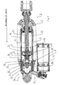
- the shock absorber is well-known per se and comprises first fastening and bearing parts 1 and second fastening and bearing parts 2. Via the first bearing parts, the shock absorber is connected to a chassis, while the second bearing parts are connected to a wheel.
- the shock absorber comprises a cylinder 3 and a piston rod 4 which works in the latter and has a piston arrangement with a first piston 5 and a second piston 6.
- the shock absorber is also provided with a main spring 7 and an accumulator container 8 which is connected to the cylinder 3 via a connecting arrangement 9.
- the accumulator container 8 comprises a floating piston 8a which separates a gas volume and a hydraulic oil volume inside the container 8.
- the first piston 5 is located in the recess 14.
- the shock absorber is shown during an ongoing compression movement in which the first piston is moving inwards into the space 14 (towards the left in the figure).
- a flow direction for the working medium (hydraulic oil) is shown by the arrow 19 and liquid passes the shim/shim pack 10 via one or more openings 20 in the piston 5.
- the working medium flows from the space 14, via the opening(s) 20, to the cylinder space 18 in front of the second piston 6.
- This is provided with one or more opening(s) 21, via which the medium 22 flows from the space 18 to a space 23 in the cylinder, above the second piston. In doing so, the medium passes the shim or shim pack 12.
- a speed-dependent damping force is obtained in a manner known per se.
- the damping force of the shock absorber is brought about essentially by the second piston.
- an increased end damping force function is obtained, which depends on the dimensioning of the first piston with regard to the opening(s) 20 and the shim(s) 10.
- the second piston occupies a position outside the cup-shaped part the whole time.
- Figure 2 shows an expansion movement in the shock absorber end position concerned, that is to say the first piston is moving out of the space or towards the right in the figure.
- the medium direction from the space 18 to the space 14 is shown by 24.
- the medium is acted on by the shim(s) on the first piston and thus passes the shim damping through the opening(s) concerned.
- the shims do not produce any greater damping force level on account of the cavitation risk in the space 14 (compare gas pressure x effective piston area).
- the medium direction from the space 23 to the space 18 through the second piston is shown by 26. This medium flow 26 is damped by the shim or shim pack 11 on the lower side of the second piston.
- the piston rod 4 according to Figure 1 is divided into two piston rod parts 4a and 4b.
- the first part 4a is essentially tubular and has a front part 4a' of reduced diameter.
- the second piston rod part 4b is designed with a bushing-like shape and, at the front, has the shape of a front spindle 4b' of reduced diameter.
- the second piston is mounted on the part 4a' and its shim or shim pack on the upper side is fixed by means of a disc-shaped element 27 which bears against a stop surface 4a" on the first piston rod part 4a.
- the first piston with its associated shim(s)/shim pack(s) is mounted on the part 4b' which, at its outer end, can interact with a locking member 28, for example a lock nut, weld joint etc.
- the bushing-shaped second piston rod part presses from underneath against the lower shim/shim pack of the second piston.
- a connection 29 between the piston rod parts can consist of a sliding connection. The parts and components shown are thus held together by means of an axial locking force effected by the locking member 28.
- the cup-shaped part 13 has an internal entry bevel 13a for the first piston which, alternatively or additionally, can be provided with a corresponding or similar entry bevel.
- the above arrangement means that during the expansion movement of the shock absorber according to Figure 2, the bleed flow can flow between the space 23, via the member 30 performing the bleed function and the part space 15b and the side hole(s) 32, and the space 18.
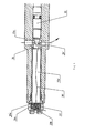
- Figure 3 shows an alternative embodiment of the parts concerned in detail. For the sake of clarity, only the front parts of the piston rod (without pistons) have been included.
- a member performing the bleed function is shown by 35.
- a part bearing a seat 36 is shown by 37.
- a front part 35a is tapered or conical and can interact with the seat 36.
- the part 35 is shown in the open position, while Figures 1 and 2 show the (corresponding) part in the closed position.
- different quantities of bleed flow 38 can pass between the part 35/35a and the seat 36. According to the above, the bleed flow passes via the passage(s) 26' and into the space 15'.
- the member 35 performing the bleed function can be of the same or similar design in Figures 1 and 2.
- a non-return valve 39 Arranged at the other end of the space 15b' is a non-return valve 39 which acts on the bleed flow.
- the non-return valve arrangement comprises a cup-shaped part 39a and a spring 39b.
- the bleed flow moves the cup-shaped part 39 to the left in the figure against the action of the spring 39a.
- This movement or displacement results in side openings 40 (compare also Figure 3a) being exposed, and the bleed flow can pass out from the space 15b' to outside the piston rod (compare the description above for Figures 1 and 2).
- Figure 4 shows the situation when the shock absorber performs a compression movement.
- the spring 39b moves the cup-shaped part 39a into a position in which the passages 40 are closed.
- the cup-shaped part can be provided with one or more bleed hole(s) 39c, via which the bleed flow 38' in the opposite direction can flow from the outside of the piston rod into the space 15b', via the seat 36 and the part 35a and out through the holes 26' (compare also the description for Figures 1 and 2).
- Different non-return valves can be provided with different numbers and sizes of bleed hole(s). A selection can then be made from among various non-return valves. In one embodiment, there are no bleed holes, and the flow 38' is then prevented completely.
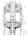
- the second piston 6' is provided with openings 41 and 42, the opening 42 being provided with a seat formation for a ball 44 (or equivalent member).
- the member 44 is pressed against the seat by a spring 45 or equivalent element which is arranged in the opening 42 and retained in the latter by means of a washer 46 (perforated washer).
Landscapes
- Engineering & Computer Science (AREA)
- General Engineering & Computer Science (AREA)
- Mechanical Engineering (AREA)
- Physics & Mathematics (AREA)
- Fluid Mechanics (AREA)
- Fluid-Damping Devices (AREA)
Applications Claiming Priority (2)
| Application Number | Priority Date | Filing Date | Title |
|---|---|---|---|
| SE9804165 | 1998-12-02 | ||
| SE9804165A SE515321C2 (sv) | 1998-12-02 | 1998-12-02 | Stötdämpare med cylinder innefattande en kolvstång med minst två kolvar |
Publications (2)
| Publication Number | Publication Date |
|---|---|
| EP1006292A1 true EP1006292A1 (de) | 2000-06-07 |
| EP1006292B1 EP1006292B1 (de) | 2006-04-05 |
Family
ID=20413520
Family Applications (1)
| Application Number | Title | Priority Date | Filing Date |
|---|---|---|---|
| EP99850144A Expired - Lifetime EP1006292B1 (de) | 1998-12-02 | 1999-10-05 | Stossdämpfer |
Country Status (5)
| Country | Link |
|---|---|
| US (1) | US6446771B1 (de) |
| EP (1) | EP1006292B1 (de) |
| JP (1) | JP2000170821A (de) |
| DE (1) | DE69930708T2 (de) |
| SE (1) | SE515321C2 (de) |
Cited By (10)
| Publication number | Priority date | Publication date | Assignee | Title |
|---|---|---|---|---|
| DE10138487C1 (de) * | 2001-08-04 | 2002-12-12 | Thyssen Krupp Bilstein Gmbh | Hydraulischer Stoßdämpfer |
| DE10223556C1 (de) * | 2002-05-28 | 2003-09-25 | Thyssen Krupp Bilstein Gmbh | Hydraulischer Stoßdämpfer |
| WO2008087660A1 (en) * | 2007-01-19 | 2008-07-24 | Tvs Motor Company Limited | Shock absorber for an automobile |
| EP1953409A1 (de) * | 2007-02-01 | 2008-08-06 | PAIOLI S.p.A. | Verfahren zur Herstellung von Stoßdämpfern und mit diesem Verfahren hergestellter Stoßdämpfer |
| WO2010101521A1 (en) * | 2009-03-03 | 2010-09-10 | öHLINS RACING AB | Shock absorber with dual piston with reduced damping in initial part of the stroke |
| FR3004501A1 (fr) * | 2013-04-16 | 2014-10-17 | Peugeot Citroen Automobiles Sa | Dispositif amortisseur hydraulique pour amortir des oscillations dans une suspension de vehicule |
| US8955654B2 (en) | 2007-12-14 | 2015-02-17 | Ohlins Racing Ab | Shock absorber with increasing damping force |
| AP3375A (en) * | 2010-11-05 | 2015-07-31 | Tvs Motor Co Ltd | Rear suspension for two wheelers |
| FR3050495A1 (fr) * | 2016-04-25 | 2017-10-27 | Peugeot Citroen Automobiles Sa | Systeme de suspension hydraulique d’un vehicule |
| LT7123B (lt) | 2024-07-04 | 2025-02-10 | Vilniaus Gedimino technikos universitetas | Elektrinio paspirtuko amortizatorius |
Families Citing this family (78)
| Publication number | Priority date | Publication date | Assignee | Title |
|---|---|---|---|---|
| DE10120918B4 (de) * | 2001-04-27 | 2011-05-05 | Continental Aktiengesellschaft | Elektrisch verstellbare, semiaktive Dämpferregelung |
| US6609597B1 (en) * | 2002-02-06 | 2003-08-26 | Enertrols, Inc. | Dampening apparatus |
| US7441640B2 (en) * | 2003-10-08 | 2008-10-28 | Peter Russell | Shock absorber apparatus |
| DE102004027885A1 (de) * | 2004-05-28 | 2005-12-22 | Dr.Ing.H.C. F. Porsche Ag | Feder-Dämpfer-Einheit für ein Fahrwerk eines Kraftfahrzeuges |
| US7628259B2 (en) * | 2004-11-08 | 2009-12-08 | Thyssenkrupp Bilstein Of America, Inc. | Fluid flow regulation of a vehicle shock absorber/damper |
| US20080035433A1 (en) * | 2005-06-13 | 2008-02-14 | Steven Strand | Hydraulic integrated parking brake system |
| US7690666B2 (en) * | 2005-08-18 | 2010-04-06 | Specialized Bicycle Components, Inc. | Position sensitive shock absorber |
| JP4753238B2 (ja) * | 2005-09-09 | 2011-08-24 | ヤマハ発動機株式会社 | 油圧緩衝器 |
| US20070144337A1 (en) * | 2005-09-29 | 2007-06-28 | Board Of Regents Of University Of Nebraska | Method and apparatus for shock wave mitigation |
| US7914031B2 (en) * | 2006-08-07 | 2011-03-29 | Specialized Bicycle Components, Inc. | Bicycle damper |
| US7878310B2 (en) * | 2006-08-07 | 2011-02-01 | Specialized Bicycle Components, Inc. | Bicycle damper |
| US8002092B2 (en) * | 2006-08-07 | 2011-08-23 | Specialized Bicycle Components, Inc. | Bicycle damper |
| US20090000886A1 (en) | 2007-06-29 | 2009-01-01 | Mcandrews Michael | Bicycle damper |
| US8059009B2 (en) * | 2006-09-15 | 2011-11-15 | Itron, Inc. | Uplink routing without routing table |
| US8162112B2 (en) | 2007-02-09 | 2012-04-24 | Competition Tire East | Methods and apparatus for protecting a shock absorber from bottoming |
| US9494209B1 (en) * | 2007-06-21 | 2016-11-15 | Bill J. Gartner | Regressive hydraulic damper |
| US8143721B2 (en) * | 2007-06-29 | 2012-03-27 | Intel Corporation | Package substrate dynamic pressure structure |
| US20090173402A1 (en) * | 2007-12-05 | 2009-07-09 | Pacific Scientific Company | Snubber valve |
| DE102008006476B4 (de) * | 2008-01-29 | 2012-05-16 | Thyssenkrupp Bilstein Suspension Gmbh | Gasdruckstoßdämpfer |
| EP3708865A1 (de) | 2008-05-09 | 2020-09-16 | Fox Factory, Inc. | Verfahren und vorrichtungen für lageempfindliche aufhängungsdämpfung |
| US9239090B2 (en) | 2009-01-07 | 2016-01-19 | Fox Factory, Inc. | Suspension damper with remotely-operable valve |
| US8276719B2 (en) * | 2008-05-09 | 2012-10-02 | Specialized Bicycle Components, Inc. | Bicycle damper |
| US11306798B2 (en) | 2008-05-09 | 2022-04-19 | Fox Factory, Inc. | Position sensitive suspension damping with an active valve |
| US9452654B2 (en) | 2009-01-07 | 2016-09-27 | Fox Factory, Inc. | Method and apparatus for an adjustable damper |
| US8627932B2 (en) | 2009-01-07 | 2014-01-14 | Fox Factory, Inc. | Bypass for a suspension damper |
| US10060499B2 (en) | 2009-01-07 | 2018-08-28 | Fox Factory, Inc. | Method and apparatus for an adjustable damper |
| US8336683B2 (en) * | 2008-05-09 | 2012-12-25 | Specialized Bicycle Components, Inc. | Bicycle damper |
| US10047817B2 (en) | 2009-01-07 | 2018-08-14 | Fox Factory, Inc. | Method and apparatus for an adjustable damper |
| US20100170760A1 (en) | 2009-01-07 | 2010-07-08 | John Marking | Remotely Operated Bypass for a Suspension Damper |
| US8960389B2 (en) * | 2009-09-18 | 2015-02-24 | Specialized Bicycle Components, Inc. | Bicycle shock absorber with slidable inertia mass |
| US8857580B2 (en) | 2009-01-07 | 2014-10-14 | Fox Factory, Inc. | Remotely operated bypass for a suspension damper |
| US9033122B2 (en) | 2009-01-07 | 2015-05-19 | Fox Factory, Inc. | Method and apparatus for an adjustable damper |
| US8393446B2 (en) | 2008-08-25 | 2013-03-12 | David M Haugen | Methods and apparatus for suspension lock out and signal generation |
| US12491961B2 (en) | 2008-11-25 | 2025-12-09 | Fox Factory, Inc. | Seat post |
| US9140325B2 (en) | 2009-03-19 | 2015-09-22 | Fox Factory, Inc. | Methods and apparatus for selective spring pre-load adjustment |
| US10036443B2 (en) | 2009-03-19 | 2018-07-31 | Fox Factory, Inc. | Methods and apparatus for suspension adjustment |
| US9422018B2 (en) | 2008-11-25 | 2016-08-23 | Fox Factory, Inc. | Seat post |
| US12122205B2 (en) | 2009-01-07 | 2024-10-22 | Fox Factory, Inc. | Active valve for an internal bypass |
| US9038791B2 (en) | 2009-01-07 | 2015-05-26 | Fox Factory, Inc. | Compression isolator for a suspension damper |
| US10821795B2 (en) | 2009-01-07 | 2020-11-03 | Fox Factory, Inc. | Method and apparatus for an adjustable damper |
| US11299233B2 (en) | 2009-01-07 | 2022-04-12 | Fox Factory, Inc. | Method and apparatus for an adjustable damper |
| TW201028329A (en) * | 2009-01-19 | 2010-08-01 | Y S S Thailand Co Ltd | Advanced triple piston damper |
| US8936139B2 (en) | 2009-03-19 | 2015-01-20 | Fox Factory, Inc. | Methods and apparatus for suspension adjustment |
| US8955653B2 (en) | 2009-10-13 | 2015-02-17 | Fox Factory, Incorporated | Methods and apparatus for controlling a fluid damper |
| US8672106B2 (en) | 2009-10-13 | 2014-03-18 | Fox Factory, Inc. | Self-regulating suspension |
| US8807300B2 (en) * | 2009-10-26 | 2014-08-19 | Fox Factory, Inc. | Methods and apparatus for managing pressurized gas in fluid dampers |
| US10953716B2 (en) | 2009-10-26 | 2021-03-23 | Fox Factory, Inc. | Methods and apparatus for managing pressurized gas in fluid dampers |
| US10697514B2 (en) | 2010-01-20 | 2020-06-30 | Fox Factory, Inc. | Remotely operated bypass for a suspension damper |
| KR100977191B1 (ko) * | 2010-02-22 | 2010-08-23 | 주식회사 케이. 아이. 씨 | 감쇠력 조절가능한 쇽업쇼바 |
| US8006993B1 (en) | 2010-05-14 | 2011-08-30 | Specialized Bicycle Components, Inc. | Bicycle frame |
| EP2402239B1 (de) | 2010-07-02 | 2020-09-02 | Fox Factory, Inc. | Einstellbare Sattelstütze |
| KR101218839B1 (ko) * | 2010-09-07 | 2013-01-07 | 주식회사 만도 | 쇽업소버 |
| EP2530355B1 (de) | 2011-05-31 | 2019-09-04 | Fox Factory, Inc. | Vorrichtungen für lageempfindliche und/oder anpassbare Aufhängungsdämpfung |
| EP2567839B1 (de) | 2011-09-12 | 2019-03-13 | Fox Factory, Inc. | Verfahren und Vorrichtung zur Aufhängungseinstellung |
| US11279199B2 (en) | 2012-01-25 | 2022-03-22 | Fox Factory, Inc. | Suspension damper with by-pass valves |
| US10330171B2 (en) | 2012-05-10 | 2019-06-25 | Fox Factory, Inc. | Method and apparatus for an adjustable damper |
| US10183539B2 (en) * | 2014-09-17 | 2019-01-22 | Fox Factory, Inc. | Shock absorber |
| US9605726B2 (en) | 2015-02-03 | 2017-03-28 | Tenneco Automotive Operating Company Inc. | Secondary dampening assembly for shock absorber |
| WO2016127076A1 (en) * | 2015-02-06 | 2016-08-11 | Tenneco Automotive Operating Company Inc. | Secondary dampening assembly for a shock absorber |
| US10737546B2 (en) | 2016-04-08 | 2020-08-11 | Fox Factory, Inc. | Electronic compression and rebound control |
| US10107352B2 (en) | 2016-04-29 | 2018-10-23 | Beijingwest Industries Co., Ltd. | Hydraulic damper with a hydraulic stop arrangement |
| US10527122B2 (en) | 2017-02-03 | 2020-01-07 | Beijingwest Industries Co., Ltd. | Hydraulic damper with a hydraulic compression stop arrangement |
| US20200102045A1 (en) * | 2017-03-22 | 2020-04-02 | Honda Motor Co., Ltd. | Steering damper |
| JP6291120B1 (ja) | 2017-08-29 | 2018-03-14 | 株式会社ショーワ | 油圧緩衝器 |
| US10670107B2 (en) * | 2017-12-15 | 2020-06-02 | Beijingwest Industries Co., Ltd. | Hydraulic damper with a hydraulic compression stop assembly |
| RU195947U1 (ru) * | 2017-12-20 | 2020-02-11 | Сергей Николаевич Калинин | Двухпоршневой амортизатор транспортного средства |
| DE102018201297B4 (de) | 2018-01-29 | 2022-07-07 | Bayerische Motoren Werke Aktiengesellschaft | Schwingungsdämpfer für ein Fahrzeug |
| WO2019246440A1 (en) | 2018-06-20 | 2019-12-26 | N10Z Performance Shocks LLC | Shock absorber assembly |
| EP3663605B1 (de) | 2018-10-30 | 2023-06-07 | Fox Factory, Inc. | Positionsempfindliche aufhängungsdämpfung mit einem aktiven ventil |
| US11602971B2 (en) | 2019-02-22 | 2023-03-14 | Fox Factory, Inc. | Mechanical bypass of electronic valve body |
| WO2021055649A1 (en) * | 2019-09-19 | 2021-03-25 | Fox Factory, Inc. | Dual live valve shock having main damper and base valve actively controlled |
| CN111043221B (zh) | 2020-01-06 | 2021-06-15 | 北京京西重工有限公司 | 阻尼器组件 |
| EP3851703A1 (de) * | 2020-01-06 | 2021-07-21 | BeijingWest Industries Co. Ltd. | Stossdämpferbaugruppe |
| US12025205B2 (en) * | 2021-04-22 | 2024-07-02 | DRiV Automotive Inc. | Hydraulic rebound stop pressure relief system |
| US12442429B2 (en) * | 2021-05-12 | 2025-10-14 | Vorsprung Technologies, Ltd. | High dynamic range suspension apparatus with selective fluid pressure communication |
| CN114046332B (zh) * | 2021-11-17 | 2023-08-04 | 浙江路得坦摩汽车部件股份有限公司 | 一种独立排气泄压的减振器 |
| US20240084874A1 (en) * | 2022-09-09 | 2024-03-14 | Wheel Pros, Llc | Shock Absorber |
| LT7178B (lt) | 2025-05-13 | 2026-01-12 | VšĮ Vilniaus Gedimino technikos universitetas | Rate integruota pakabos sistema mikromobiliosioms transporto priemonėms |
Citations (7)
| Publication number | Priority date | Publication date | Assignee | Title |
|---|---|---|---|---|
| GB2202921A (en) * | 1987-03-31 | 1988-10-05 | Josiah Edward Pitt | Damper |
| JPH0493533U (de) | 1990-12-28 | 1992-08-13 | ||
| US5157806A (en) * | 1991-12-09 | 1992-10-27 | George Wartian | Door closing piston-cylinder assembly |
| EP0565832A1 (de) * | 1992-04-11 | 1993-10-20 | AUGUST BILSTEIN GMBH & CO. KG | Hydraulischer Schwingungsdämpfer für Kraftfahrzeuge |
| EP0748950A1 (de) * | 1995-05-18 | 1996-12-18 | Öhlins Racing Ab | Stossdämpfer und deren Benutzung |
| EP0816712A2 (de) * | 1996-06-25 | 1998-01-07 | Öhlins Racing Ab | Stossdämpfer |
| US5823306A (en) * | 1996-11-12 | 1998-10-20 | Tenneco Automotive Inc. | Stroke dependent damping |
Family Cites Families (16)
| Publication number | Priority date | Publication date | Assignee | Title |
|---|---|---|---|---|
| US1331564A (en) * | 1915-10-18 | 1920-02-24 | Pneumatic Cushion Company | Pneumatic cushion for vehicles |
| GB925877A (en) | 1959-11-10 | 1963-05-08 | Peters G D & Co Ltd | Improvements in and relating to cushioning or shock-absorbing devices |
| US3175645A (en) | 1962-09-13 | 1965-03-30 | Stabilus Ind Handels Gmbh | Shock absorber with primary and secondary damping chambers |
| GB1132038A (en) * | 1966-03-17 | 1968-10-30 | Woodhead Mfg Company Ltd | Vibration dampers |
| DE7000825U (de) * | 1970-01-13 | 1970-09-17 | Bilstein August Fa | Kolben fuer hydraulische schwingungsdaempfer. |
| GB1305311A (de) | 1970-04-13 | 1973-01-31 | ||
| US3726368A (en) * | 1970-10-30 | 1973-04-10 | P Taylor | Fluid amplified liquid spring shocks and/or shock absorbers |
| JPS5254716Y2 (de) * | 1972-04-25 | 1977-12-10 | ||
| DE2659488A1 (de) * | 1976-12-30 | 1978-07-06 | Stabilus Gmbh | Gasfeder mit arretierkolben |
| US4356898A (en) * | 1979-11-20 | 1982-11-02 | Maremont Corporation | Valve assembly and reduced harshness shock absorber embodying the same |
| DE3518327A1 (de) * | 1985-05-22 | 1986-11-27 | Boge Gmbh, 5208 Eitorf | Hydraulischer, verstellbarer schwingungsdaempfer |
| JPH02275128A (ja) * | 1989-04-17 | 1990-11-09 | Atsugi Unisia Corp | 液圧緩衝器の減衰力可変システム |
| US5409087A (en) | 1992-04-11 | 1995-04-25 | August Bilstein Gmbh & Co. Kg | Hydraulic dashpot for motor vehicles |
| JPH0722151U (ja) * | 1993-09-30 | 1995-04-21 | カヤバ工業株式会社 | 油圧緩衝器の圧側オイルロック装置 |
| JPH07233842A (ja) * | 1994-02-21 | 1995-09-05 | Showa:Kk | 油圧緩衝器のオイルロック装置 |
| JPH07238975A (ja) * | 1994-02-24 | 1995-09-12 | Unisia Jecs Corp | 減衰力可変型ショックアブソーバ |
-
1998
- 1998-12-02 SE SE9804165A patent/SE515321C2/sv not_active IP Right Cessation
-
1999
- 1999-10-05 EP EP99850144A patent/EP1006292B1/de not_active Expired - Lifetime
- 1999-10-05 DE DE69930708T patent/DE69930708T2/de not_active Expired - Lifetime
- 1999-11-10 US US09/437,212 patent/US6446771B1/en not_active Expired - Fee Related
- 1999-12-02 JP JP11343872A patent/JP2000170821A/ja active Pending
Patent Citations (7)
| Publication number | Priority date | Publication date | Assignee | Title |
|---|---|---|---|---|
| GB2202921A (en) * | 1987-03-31 | 1988-10-05 | Josiah Edward Pitt | Damper |
| JPH0493533U (de) | 1990-12-28 | 1992-08-13 | ||
| US5157806A (en) * | 1991-12-09 | 1992-10-27 | George Wartian | Door closing piston-cylinder assembly |
| EP0565832A1 (de) * | 1992-04-11 | 1993-10-20 | AUGUST BILSTEIN GMBH & CO. KG | Hydraulischer Schwingungsdämpfer für Kraftfahrzeuge |
| EP0748950A1 (de) * | 1995-05-18 | 1996-12-18 | Öhlins Racing Ab | Stossdämpfer und deren Benutzung |
| EP0816712A2 (de) * | 1996-06-25 | 1998-01-07 | Öhlins Racing Ab | Stossdämpfer |
| US5823306A (en) * | 1996-11-12 | 1998-10-20 | Tenneco Automotive Inc. | Stroke dependent damping |
Cited By (12)
| Publication number | Priority date | Publication date | Assignee | Title |
|---|---|---|---|---|
| DE10138487C1 (de) * | 2001-08-04 | 2002-12-12 | Thyssen Krupp Bilstein Gmbh | Hydraulischer Stoßdämpfer |
| US6662914B2 (en) * | 2001-08-04 | 2003-12-16 | Krupp Bilstein Gmbh | Hydraulic dashpot |
| DE10223556C1 (de) * | 2002-05-28 | 2003-09-25 | Thyssen Krupp Bilstein Gmbh | Hydraulischer Stoßdämpfer |
| WO2008087660A1 (en) * | 2007-01-19 | 2008-07-24 | Tvs Motor Company Limited | Shock absorber for an automobile |
| EP1953409A1 (de) * | 2007-02-01 | 2008-08-06 | PAIOLI S.p.A. | Verfahren zur Herstellung von Stoßdämpfern und mit diesem Verfahren hergestellter Stoßdämpfer |
| US8955654B2 (en) | 2007-12-14 | 2015-02-17 | Ohlins Racing Ab | Shock absorber with increasing damping force |
| EP2232095A4 (de) * | 2007-12-14 | 2017-08-02 | Öhlins Racing Ab | Stossdämpfer mit zunehmender dämpfkraft |
| WO2010101521A1 (en) * | 2009-03-03 | 2010-09-10 | öHLINS RACING AB | Shock absorber with dual piston with reduced damping in initial part of the stroke |
| AP3375A (en) * | 2010-11-05 | 2015-07-31 | Tvs Motor Co Ltd | Rear suspension for two wheelers |
| FR3004501A1 (fr) * | 2013-04-16 | 2014-10-17 | Peugeot Citroen Automobiles Sa | Dispositif amortisseur hydraulique pour amortir des oscillations dans une suspension de vehicule |
| FR3050495A1 (fr) * | 2016-04-25 | 2017-10-27 | Peugeot Citroen Automobiles Sa | Systeme de suspension hydraulique d’un vehicule |
| LT7123B (lt) | 2024-07-04 | 2025-02-10 | Vilniaus Gedimino technikos universitetas | Elektrinio paspirtuko amortizatorius |
Also Published As
| Publication number | Publication date |
|---|---|
| DE69930708T2 (de) | 2007-01-11 |
| EP1006292B1 (de) | 2006-04-05 |
| DE69930708D1 (de) | 2006-05-18 |
| SE9804165L (sv) | 2000-06-03 |
| US20020053493A1 (en) | 2002-05-09 |
| JP2000170821A (ja) | 2000-06-23 |
| SE515321C2 (sv) | 2001-07-16 |
| SE9804165D0 (sv) | 1998-12-02 |
| US6446771B1 (en) | 2002-09-10 |
Similar Documents
| Publication | Publication Date | Title |
|---|---|---|
| US6446771B1 (en) | Shock absorber | |
| US6213263B1 (en) | Oil damper system | |
| US6119830A (en) | Flow sensitive, acceleration sensitive shock absorber | |
| US5598903A (en) | Acceleration sensitive flow sensitive mcpherson strut | |
| EP1116610A2 (de) | Aufhängungsvorrichtung für ein vierrädriges Fahrzeug | |
| JP2009275912A (ja) | フロントフォーク | |
| JP4181940B2 (ja) | リリーフ弁および車高調整機能付油圧緩衝器 | |
| WO2012039396A1 (ja) | フロントフォーク | |
| JP2000018308A (ja) | 油圧緩衝器 | |
| JP2002127727A (ja) | サスペンション装置 | |
| JP4137541B2 (ja) | 車両用の油圧緩衝器 | |
| WO1998014718A1 (en) | ACCELERATION SENSITIVE FLOW SENSITIVE McPHERSON STRUT | |
| JPH1182602A (ja) | 減衰力調整式油圧緩衝器 | |
| US4475635A (en) | Vortex flow shock absorber with one-way valve | |
| JP2529993Y2 (ja) | 倒立型フロントフォーク | |
| JP2511984Y2 (ja) | 油圧緩衝器のアンチダイブ機構 | |
| JP2000065117A (ja) | フロントフォーク | |
| JPS6012274B2 (ja) | 二輪車等のフロントフオ−ク | |
| JPH04337138A (ja) | 油圧緩衝器 | |
| JP2010242888A (ja) | ダンパ | |
| JP4137545B2 (ja) | 車両用の油圧緩衝器 | |
| JPS5926817B2 (ja) | 車輛用緩衝器 | |
| JP2529994Y2 (ja) | 倒立型フロントフォーク | |
| JPH07119782A (ja) | 油圧緩衝器 | |
| JP2009264489A (ja) | フロントフォーク |
Legal Events
| Date | Code | Title | Description |
|---|---|---|---|
| PUAI | Public reference made under article 153(3) epc to a published international application that has entered the european phase |
Free format text: ORIGINAL CODE: 0009012 |
|
| AK | Designated contracting states |
Kind code of ref document: A1 Designated state(s): DE FR GB IT NL |
|
| AX | Request for extension of the european patent |
Free format text: AL;LT;LV;MK;RO;SI |
|
| 17P | Request for examination filed |
Effective date: 20000710 |
|
| AKX | Designation fees paid |
Free format text: DE FR GB IT NL |
|
| 17Q | First examination report despatched |
Effective date: 20030506 |
|
| TPAC | Observations filed by third parties |
Free format text: ORIGINAL CODE: EPIDOSNTIPA |
|
| GRAP | Despatch of communication of intention to grant a patent |
Free format text: ORIGINAL CODE: EPIDOSNIGR1 |
|
| GRAS | Grant fee paid |
Free format text: ORIGINAL CODE: EPIDOSNIGR3 |
|
| GRAA | (expected) grant |
Free format text: ORIGINAL CODE: 0009210 |
|
| AK | Designated contracting states |
Kind code of ref document: B1 Designated state(s): DE FR GB IT NL |
|
| PG25 | Lapsed in a contracting state [announced via postgrant information from national office to epo] |
Ref country code: IT Free format text: LAPSE BECAUSE OF FAILURE TO SUBMIT A TRANSLATION OF THE DESCRIPTION OR TO PAY THE FEE WITHIN THE PRESCRIBED TIME-LIMIT;WARNING: LAPSES OF ITALIAN PATENTS WITH EFFECTIVE DATE BEFORE 2007 MAY HAVE OCCURRED AT ANY TIME BEFORE 2007. THE CORRECT EFFECTIVE DATE MAY BE DIFFERENT FROM THE ONE RECORDED. Effective date: 20060405 |
|
| REG | Reference to a national code |
Ref country code: GB Ref legal event code: FG4D |
|
| REF | Corresponds to: |
Ref document number: 69930708 Country of ref document: DE Date of ref document: 20060518 Kind code of ref document: P |
|
| ET | Fr: translation filed | ||
| PLBE | No opposition filed within time limit |
Free format text: ORIGINAL CODE: 0009261 |
|
| STAA | Information on the status of an ep patent application or granted ep patent |
Free format text: STATUS: NO OPPOSITION FILED WITHIN TIME LIMIT |
|
| 26N | No opposition filed |
Effective date: 20070108 |
|
| PGFP | Annual fee paid to national office [announced via postgrant information from national office to epo] |
Ref country code: FR Payment date: 20131023 Year of fee payment: 15 Ref country code: DE Payment date: 20131002 Year of fee payment: 15 Ref country code: GB Payment date: 20131007 Year of fee payment: 15 |
|
| PGFP | Annual fee paid to national office [announced via postgrant information from national office to epo] |
Ref country code: NL Payment date: 20131001 Year of fee payment: 15 Ref country code: IT Payment date: 20131018 Year of fee payment: 15 |
|
| REG | Reference to a national code |
Ref country code: DE Ref legal event code: R119 Ref document number: 69930708 Country of ref document: DE |
|
| REG | Reference to a national code |
Ref country code: NL Ref legal event code: V1 Effective date: 20150501 |
|
| GBPC | Gb: european patent ceased through non-payment of renewal fee |
Effective date: 20141005 |
|
| PG25 | Lapsed in a contracting state [announced via postgrant information from national office to epo] |
Ref country code: GB Free format text: LAPSE BECAUSE OF NON-PAYMENT OF DUE FEES Effective date: 20141005 Ref country code: DE Free format text: LAPSE BECAUSE OF NON-PAYMENT OF DUE FEES Effective date: 20150501 |
|
| REG | Reference to a national code |
Ref country code: FR Ref legal event code: ST Effective date: 20150630 |
|
| PG25 | Lapsed in a contracting state [announced via postgrant information from national office to epo] |
Ref country code: FR Free format text: LAPSE BECAUSE OF NON-PAYMENT OF DUE FEES Effective date: 20141031 Ref country code: NL Free format text: LAPSE BECAUSE OF NON-PAYMENT OF DUE FEES Effective date: 20150501 Ref country code: IT Free format text: LAPSE BECAUSE OF NON-PAYMENT OF DUE FEES Effective date: 20141005 |