EP1006293A1 - Spannfutterantrieb - Google Patents
Spannfutterantrieb Download PDFInfo
- Publication number
- EP1006293A1 EP1006293A1 EP98122823A EP98122823A EP1006293A1 EP 1006293 A1 EP1006293 A1 EP 1006293A1 EP 98122823 A EP98122823 A EP 98122823A EP 98122823 A EP98122823 A EP 98122823A EP 1006293 A1 EP1006293 A1 EP 1006293A1
- Authority
- EP
- European Patent Office
- Prior art keywords
- drive
- chuck
- toothed
- shaft
- drive shaft
- Prior art date
- Legal status (The legal status is an assumption and is not a legal conclusion. Google has not performed a legal analysis and makes no representation as to the accuracy of the status listed.)
- Granted
Links
Images

Classifications
-
- F—MECHANICAL ENGINEERING; LIGHTING; HEATING; WEAPONS; BLASTING
- F16—ENGINEERING ELEMENTS AND UNITS; GENERAL MEASURES FOR PRODUCING AND MAINTAINING EFFECTIVE FUNCTIONING OF MACHINES OR INSTALLATIONS; THERMAL INSULATION IN GENERAL
- F16H—GEARING
- F16H7/00—Gearings for conveying rotary motion by endless flexible members
- F16H7/02—Gearings for conveying rotary motion by endless flexible members with belts; with V-belts
- F16H7/023—Gearings for conveying rotary motion by endless flexible members with belts; with V-belts with belts having a toothed contact surface or regularly spaced bosses or hollows for slipless or nearly slipless meshing with complementary profiled contact surface of a pulley
-
- B—PERFORMING OPERATIONS; TRANSPORTING
- B23—MACHINE TOOLS; METAL-WORKING NOT OTHERWISE PROVIDED FOR
- B23Q—DETAILS, COMPONENTS, OR ACCESSORIES FOR MACHINE TOOLS, e.g. ARRANGEMENTS FOR COPYING OR CONTROLLING; MACHINE TOOLS IN GENERAL CHARACTERISED BY THE CONSTRUCTION OF PARTICULAR DETAILS OR COMPONENTS; COMBINATIONS OR ASSOCIATIONS OF METAL-WORKING MACHINES, NOT DIRECTED TO A PARTICULAR RESULT
- B23Q5/00—Driving or feeding mechanisms; Control arrangements therefor
- B23Q5/54—Arrangements or details not restricted to group B23Q5/02 or group B23Q5/22 respectively, e.g. control handles
- B23Q5/56—Preventing backlash
Definitions
- the invention relates to a chuck drive, in particular a faceplate drive for a Lathe, with a drive motor, one Drive shaft, a chuck shaft and a Translation means between the drive shaft and Chuck shaft.
- Chuck drives of this type are known from the prior art in a large number of variations.
- Mechanical transmissions are used as transmission means in the most common chuck drives. These mechanical gears have proven themselves in a variety of applications. They ensure exact gear ratios and enable the transmission of high to very high torques.
- the use of gears as a means of translation is also problematic from various points of view. First of all, it is problematic that no play-free torque transmission can be guaranteed with simple gear designs. This leads to problems in particular if the cutting tools used on the lathe introduce variable forces into the chuck drive depending on the angle of rotation of the workpiece. These variations in force occur, for example, when a workpiece is turned off, which has, for example, radial grooves.
- Chuck drives are also from the prior art known that the required play-free drive of the Ensure chuck. This too Chuck drives work on the basis of a gear, with different gears within this gear working tense against each other. These well-known Chuck drives are now one way of doing this problematic that they are very expensive to manufacture and are accordingly expensive and on the other hand, as well the simple gears are comparatively loud, i.e. generate high sound pressure levels.
- the invention based on the task To provide a chuck drive, the one backlash-free torque transmission with simple means high running culture guaranteed.
- the teaching of the invention enables through use of inexpensive pulleys and timing belts Realization of a translation medium for one Chuck drive, the tensioning of the at least on two different toothed pulleys running timing belt a backlash-free Torque transmission through the chuck drive is guaranteed.
- the well-known Advantages of toothed belt drives namely that in Almost noiseless running compared to gearboxes.
- a first advantageous embodiment of the Chuck drive according to the invention in that a Partial toothed disk on the drive shaft at least one Wedge connection is attached and the other Part toothed washer on the drive shaft over at least one Ring clamping element is attached.
- the advantage is the smaller drive pulley in two Part tooth washers to share.
- the invention In principle, however, advantages can be achieved by either split drive pulley as well as by a split Chuck tooth washer, as well as the fact that both Toothed lock washers are realized. Is constructive however, the pitch of the drive pulley is preferable. Through the wedge connection between a toothed washer and in particular the drive shaft ensures that this toothed pulley rotatably with the drive shaft connected is.
- Tension between the on the different To produce partial toothed pulleys on the toothed belt is the other toothed pulley over the drive shaft attached at least one ring clamping element, which it enables this toothed pulley when loosened Ring clamping element compared to that via a wedge connection partial toothed disk attached to the drive shaft to turn the toothed belt so far that the desired tension is present. Then then the ring clamping element is tightened and provides a rotationally fixed Connection between the other pulley and the Drive shaft forth, so that the bracing is maintained.
- the use of ring clamping elements is particularly advantageous because it is easy to are handling and at the same time the non-slip Transmission of high to very high torques guarantee.
- the torque needed to get the required Making tension is particularly easy initiated in the other pulley that the over Ring clamping elements attached to the drive shaft Partial toothed washer on an axial outer surface at least has two axially extending bores. This Bores are used to engage a spanner about the moment then necessary for tension is applied.
- the quality of the backlash-free transmission is further improved in that the drive toothed disk and / or the chuck toothed disk has a reduced tooth play.
- the backlash is -0.1 mm.
- the tooth play in known toothed belt drives is usually +0.3 mm.
- the narrow tooth gap ensures that the toothed belt runs absolutely free of play even on the respective toothed pulley.
- the chuck drive in C-axis mode is Drive motor as a digitally controlled servo motor trained and on the chuck a transducer for a Control of the drive motor arranged. This is ensures that the control of the drive motor without play over the angular position of the chuck shaft is informed.
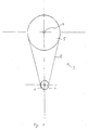
- Fig. 1 shows an embodiment of a Face plate drive for a vertical or horizontal lathe, with a not shown Drive motor, a drive shaft 1, one Chuck shaft 2 and a translation means 3 between drive shaft 1 and chuck shaft 2.
- the translation means 3 on the drive shaft 1 a drive pulley 4 and a chuck toothed disk 5 on the chuck shaft 2 arranged.
- Wedge connection 9 can also be the partial toothed disk 6 additionally via one or two ring clamping elements on the Drive shaft attached to a higher one To ensure torque transmission.
- the Ring clamping elements 10, 11 are in the in Fig. 2nd illustrated embodiment via a Pressure plate 12 and an associated screw 13 dressed.
- the timing belts 8 are against each other as follows tense. After placing the toothed belt 8 on the Drive toothed disk 4 and chuck toothed disk 5 are the straps 8 first in a known manner and Way excited. Here, the partial toothed disks 6, 7 the drive pulley 4 not yet against each other twisted. So after the toothed belt drive in known Has been discontinued Ring clamping elements 10, 11 loosened so far that the Partial toothed disk 7 can rotate on the drive shaft 1. At the same time, the drive shaft 1 is blocked. This cannot, for example, have a holding torque of shown drive motor happen, or via a separate brake, which is also used for other purposes the chuck shaft.
- the tooth play of the drive pulley and the chuck toothed washer is reduced. Specifically means this is that the distance between two tooth flanks on the Drive pulley as well on the Chuck tooth washer is about 0.1 mm less than the distance between two flanks on the toothed belt 8. Of course, this applies to the same Tooth flanks of two successive teeth.
Landscapes
- Engineering & Computer Science (AREA)
- General Engineering & Computer Science (AREA)
- Mechanical Engineering (AREA)
- Pulleys (AREA)
- Devices For Conveying Motion By Means Of Endless Flexible Members (AREA)
- Gripping On Spindles (AREA)
- Electrical Discharge Machining, Electrochemical Machining, And Combined Machining (AREA)
- Power Steering Mechanism (AREA)
Abstract
Description
Zunächst ist problematisch, daß mit einfachen Getriebekonstruktionen keine spielfreie Momentenübertragung gewährleistet werden kann. Dies führt insbesondere dann zu Problemen, wenn die an der Drehmaschine eingesetzten, spanabhebenden Werkzeuge abhängig vom Drehwinkel des Werkstücks variable Kräfte in den Spannfutterantrieb einleiten. Diese Kräftevariationen treten etwa dann auf, wenn ein Werkstück abgedreht wird, welches beispielsweise radial verlaufende Nuten aufweist. Diese Kraftvariationen treten aber insbesondere auch dann auf, wenn eine Drehmaschine im sog. C-Achsbetrieb eingesetzt wird. Bei diesem C-Achsbetrieb wird das Werkstück durch den Spannfutterantrieb gedreht, wobei gleichzeitig ein beliebiges Fräsprofil am Umfang des Werkstücks gefahren wird. Auch hier treten starke Kraftvariationen auf, die dazu führen, daß die vom Spannfutterantrieb übertragenen Drehmomente stark variieren. Um eine einwandfreie und reproduzierbare Bearbeitung des Werkstückes zu gewährleisten, ist es dabei notwendig, daß der Spannfutterantrieb absolut spielfrei arbeitet, d.h. unabhängig von den übertragenen Momenten eine gleichmäßige Winkelgeschwindigkeit des Spannfutters gewährleistet.
Üblicherweise beträgt das Zahnspiel bei bekannten Zahnriemenantrieben +0,3 mm. Durch die enge Zahnlücke ist gewährleistet, daß der Zahnriemen selbst auf der jeweiligen Zahnscheibe absolut spielfrei läuft.
- Fig. 1
- ein Ausführungsbeispiel eines erfindungsgemäßen Spannfutterantriebs in einer Ansicht aus axialer Richtung und
- Fig. 2
- einen axialen Schnitt durch die Antriebswelle und die Antriebszahnscheiben des Ausführungsbeispiels.
Claims (7)
- Spannfutterantrieb, insbesondere
Planscheibenantrieb, für eine Drehmaschine, mit einem Antriebsmotor, einer Antriebswelle (1), einer Spannfutterwelle (2) und einem Übersetzungsmittel (3) zwischen Antriebswelle (1) und Spannfutterwelle (2), dadurch gekennzeichnet, daß als Übersetzungsmittel (3) auf der Antriebswelle (1) eine Antriebszahnscheibe (4) und auf der Spannfutterwelle (2) eine Spannfutterzahnscheibe (5) angeordnet ist, die Anriebszahnscheibe (4) und/oder die Spannfutterzahnscheibe (5) in einer Ebene senkrecht zur Antriebswelle (1) und/oder Spannfutterwelle (2) in mindestens zwei Teilzahnscheiben (6, 7) geteilt ist, die Antriebszahnscheibe (4) und die Spannfutterzahnscheibe (5) über mindestens zwei Zahnriemen (8) verbunden sind, die Breite der Zahnriemen (8) der Höhe der Teilzahnscheiben (6, 7) entspricht und die auf die Teilzahnscheiben (6, 7) aufgelegten Zahnriemen (8) gegeneinander verspannt sind. - Spannfutterantrieb nach Anspruch 1,
dadurch gekennzeichnet, daß eine Teilzahnscheibe (6) auf der Antriebswelle (1) zumindest über eine Keilverbindung (9) befestigt ist und die andere Teilzahnscheibe (7) auf der Antriebswelle (1) über mindestens ein Ringspannelement (10, 11) befestigt ist. - Spannfutterantrieb nach Anspruch 1 oder 2,
dadurch gekennzeichnet, daß die über Ringspannelemente (10, 11) auf der Antriebswelle (1) befestigte Teilzahnscheibe (7) auf einer axialen Außenfläche mindestens zwei axial verlaufende Bohrungen (14, 15) aufweist. - Spannfutterantrieb nach einem der Ansprüche 1 bis 3,
dadurch gekennzeichnet, daß die Antriebszahnscheibe (4) und/oder die Spannfutterzahnscheibe (5) ein verkleinertes Zahnspiel aufweist. - Spannfutterantrieb nach Anspruch 4,
dadurch gekennzeichnet, daß das Zahnspiel -0,1 mm beträgt. - Spannfutterantrieb nach einem der Ansprüche 1 bis 5,
dadurch gekennzeichnet, daß das Vorspannmoment größer als das maximal auftretende Antriebsmoment ist. - Spannfutterantrieb nach einem der Ansprüche 1 bis 6,
dadurch gekennzeichnet, daß der Antriebsmotor als digital geregelter Servomotor ausgebildet ist und an dem Spannfutter ein Meßgeber für eine Steuerung des Antriebsmotors angeordnet ist.
Priority Applications (3)
| Application Number | Priority Date | Filing Date | Title |
|---|---|---|---|
| EP98122823A EP1006293B1 (de) | 1998-12-01 | 1998-12-01 | Spannfutterantrieb |
| DE59808836T DE59808836D1 (de) | 1998-12-01 | 1998-12-01 | Spannfutterantrieb |
| AT98122823T ATE243821T1 (de) | 1998-12-01 | 1998-12-01 | Spannfutterantrieb |
Applications Claiming Priority (1)
| Application Number | Priority Date | Filing Date | Title |
|---|---|---|---|
| EP98122823A EP1006293B1 (de) | 1998-12-01 | 1998-12-01 | Spannfutterantrieb |
Publications (2)
| Publication Number | Publication Date |
|---|---|
| EP1006293A1 true EP1006293A1 (de) | 2000-06-07 |
| EP1006293B1 EP1006293B1 (de) | 2003-06-25 |
Family
ID=8233072
Family Applications (1)
| Application Number | Title | Priority Date | Filing Date |
|---|---|---|---|
| EP98122823A Expired - Lifetime EP1006293B1 (de) | 1998-12-01 | 1998-12-01 | Spannfutterantrieb |
Country Status (3)
| Country | Link |
|---|---|
| EP (1) | EP1006293B1 (de) |
| AT (1) | ATE243821T1 (de) |
| DE (1) | DE59808836D1 (de) |
Citations (7)
| Publication number | Priority date | Publication date | Assignee | Title |
|---|---|---|---|---|
| GB962154A (en) * | 1959-09-08 | 1964-07-01 | Ferguson Res Ltd Harry | Improvements in and relating to chain-and-sprocket drives |
| DD215833A1 (de) * | 1982-12-28 | 1984-11-21 | Robotron Rechen Und Schreibtec | Zugmittelgetriebe fuer zahnriemen |
| JPS6323064A (ja) * | 1986-07-15 | 1988-01-30 | Fanuc Ltd | 減速用駆動機構のバツクラツシ除去装置 |
| EP0260477A2 (de) * | 1986-09-13 | 1988-03-23 | Kurt Hoffmann GmbH & Co.KG | Senkrechträummaschine |
| US4747321A (en) * | 1987-07-17 | 1988-05-31 | Lockheed Corporation | Anti-backlash gear assembly |
| NL9001378A (nl) * | 1990-06-18 | 1992-01-16 | Philips Nv | Meervoudige tandriemoverbrenging. |
| DE19541790A1 (de) * | 1995-11-09 | 1997-05-15 | Audi Ag | Riementrieb |
-
1998
- 1998-12-01 AT AT98122823T patent/ATE243821T1/de not_active IP Right Cessation
- 1998-12-01 DE DE59808836T patent/DE59808836D1/de not_active Expired - Lifetime
- 1998-12-01 EP EP98122823A patent/EP1006293B1/de not_active Expired - Lifetime
Patent Citations (7)
| Publication number | Priority date | Publication date | Assignee | Title |
|---|---|---|---|---|
| GB962154A (en) * | 1959-09-08 | 1964-07-01 | Ferguson Res Ltd Harry | Improvements in and relating to chain-and-sprocket drives |
| DD215833A1 (de) * | 1982-12-28 | 1984-11-21 | Robotron Rechen Und Schreibtec | Zugmittelgetriebe fuer zahnriemen |
| JPS6323064A (ja) * | 1986-07-15 | 1988-01-30 | Fanuc Ltd | 減速用駆動機構のバツクラツシ除去装置 |
| EP0260477A2 (de) * | 1986-09-13 | 1988-03-23 | Kurt Hoffmann GmbH & Co.KG | Senkrechträummaschine |
| US4747321A (en) * | 1987-07-17 | 1988-05-31 | Lockheed Corporation | Anti-backlash gear assembly |
| NL9001378A (nl) * | 1990-06-18 | 1992-01-16 | Philips Nv | Meervoudige tandriemoverbrenging. |
| DE19541790A1 (de) * | 1995-11-09 | 1997-05-15 | Audi Ag | Riementrieb |
Non-Patent Citations (1)
| Title |
|---|
| PATENT ABSTRACTS OF JAPAN vol. 12, no. 227 (M - 713) 28 June 1988 (1988-06-28) * |
Also Published As
| Publication number | Publication date |
|---|---|
| DE59808836D1 (de) | 2003-07-31 |
| ATE243821T1 (de) | 2003-07-15 |
| EP1006293B1 (de) | 2003-06-25 |
Similar Documents
| Publication | Publication Date | Title |
|---|---|---|
| DE3510605C2 (de) | ||
| EP0021223B1 (de) | Druckkammgetriebe | |
| DE10008911A1 (de) | Vorrichtung zur Vermeidung von Zahnradspiel in Getrieben | |
| EP0084197A1 (de) | Planetengetriebe | |
| DE102010056068A1 (de) | Planetengetriebe, Planet und Planetenrad für ein Planetengetriebe, Handantriebseinrichtung und Antrieb mit einem Planetengetriebe | |
| DE1952545A1 (de) | Stirnradgetriebe mit Mitteln zur Beseitigung des Zahnflankenspiels | |
| DE3739238A1 (de) | Spielfreies kompakt-untersetzungsgetriebe | |
| DE19900010C2 (de) | Spielfreies Reibradgetriebe | |
| EP0075667A1 (de) | Stellantrieb mit einem Planetengetriebe | |
| EP1188002B1 (de) | Planetengetriebe | |
| EP3488971A1 (de) | Elektrisch antreibbare schwenkvorrichtung | |
| DE2726080C2 (de) | Anordnung zum Verschieben eines Wälzlagers in beiden axialen Richtungen | |
| DE4241273C2 (de) | Antriebsvorrichtung für die Umwandlung drehender Bewegungen in lineare Bewegungen und umgekehrt | |
| DE112004000121T5 (de) | Hypoidgetriebevorrichtung | |
| EP2347148B2 (de) | Zahnrad und trommelantrieb | |
| EP3143294A1 (de) | Vorrichtung zum sichern eines spannelements gegen ungewolltes lösen | |
| DE102008036743A1 (de) | Getriebe mit Slots | |
| EP1006293B1 (de) | Spannfutterantrieb | |
| EP1045168A2 (de) | Servoantriebssystem | |
| EP0642881A1 (de) | Spielfreier Rundtischantrieb einer Werkzeugmaschine | |
| DE3006787C2 (de) | Getriebe | |
| DE20115350U1 (de) | Drehverbindung | |
| EP0999032A1 (de) | Getriebe insbesondere für Doppelschneckenextruder | |
| DE4105995C2 (de) | Zahnradgetriebe | |
| EP1747382A1 (de) | Wälzlager mit exzentrischem aussenring |
Legal Events
| Date | Code | Title | Description |
|---|---|---|---|
| PUAI | Public reference made under article 153(3) epc to a published international application that has entered the european phase |
Free format text: ORIGINAL CODE: 0009012 |
|
| AK | Designated contracting states |
Kind code of ref document: A1 Designated state(s): AT BE CH DE ES FI GB IT LI NL SE |
|
| AX | Request for extension of the european patent |
Free format text: AL;LT;LV;MK;RO;SI |
|
| 17P | Request for examination filed |
Effective date: 20000629 |
|
| AKX | Designation fees paid |
Free format text: AT BE CH DE ES FI GB IT LI NL SE |
|
| 17Q | First examination report despatched |
Effective date: 20020218 |
|
| GRAH | Despatch of communication of intention to grant a patent |
Free format text: ORIGINAL CODE: EPIDOS IGRA |
|
| GRAH | Despatch of communication of intention to grant a patent |
Free format text: ORIGINAL CODE: EPIDOS IGRA |
|
| GRAA | (expected) grant |
Free format text: ORIGINAL CODE: 0009210 |
|
| AK | Designated contracting states |
Designated state(s): AT BE CH DE ES FI GB IT LI NL SE |
|
| PG25 | Lapsed in a contracting state [announced via postgrant information from national office to epo] |
Ref country code: NL Free format text: LAPSE BECAUSE OF FAILURE TO SUBMIT A TRANSLATION OF THE DESCRIPTION OR TO PAY THE FEE WITHIN THE PRESCRIBED TIME-LIMIT Effective date: 20030625 Ref country code: IT Free format text: LAPSE BECAUSE OF FAILURE TO SUBMIT A TRANSLATION OF THE DESCRIPTION OR TO PAY THE FEE WITHIN THE PRESCRIBED TIME-LIMIT;WARNING: LAPSES OF ITALIAN PATENTS WITH EFFECTIVE DATE BEFORE 2007 MAY HAVE OCCURRED AT ANY TIME BEFORE 2007. THE CORRECT EFFECTIVE DATE MAY BE DIFFERENT FROM THE ONE RECORDED. Effective date: 20030625 Ref country code: GB Free format text: LAPSE BECAUSE OF FAILURE TO SUBMIT A TRANSLATION OF THE DESCRIPTION OR TO PAY THE FEE WITHIN THE PRESCRIBED TIME-LIMIT Effective date: 20030625 Ref country code: FI Free format text: LAPSE BECAUSE OF FAILURE TO SUBMIT A TRANSLATION OF THE DESCRIPTION OR TO PAY THE FEE WITHIN THE PRESCRIBED TIME-LIMIT Effective date: 20030625 |
|
| REG | Reference to a national code |
Ref country code: GB Ref legal event code: FG4D Free format text: NOT ENGLISH |
|
| REG | Reference to a national code |
Ref country code: CH Ref legal event code: EP |
|
| REF | Corresponds to: |
Ref document number: 59808836 Country of ref document: DE Date of ref document: 20030731 Kind code of ref document: P |
|
| PG25 | Lapsed in a contracting state [announced via postgrant information from national office to epo] |
Ref country code: SE Free format text: LAPSE BECAUSE OF FAILURE TO SUBMIT A TRANSLATION OF THE DESCRIPTION OR TO PAY THE FEE WITHIN THE PRESCRIBED TIME-LIMIT Effective date: 20030925 |
|
| NLV1 | Nl: lapsed or annulled due to failure to fulfill the requirements of art. 29p and 29m of the patents act | ||
| PG25 | Lapsed in a contracting state [announced via postgrant information from national office to epo] |
Ref country code: AT Free format text: LAPSE BECAUSE OF NON-PAYMENT OF DUE FEES Effective date: 20031201 |
|
| PG25 | Lapsed in a contracting state [announced via postgrant information from national office to epo] |
Ref country code: ES Free format text: LAPSE BECAUSE OF FAILURE TO SUBMIT A TRANSLATION OF THE DESCRIPTION OR TO PAY THE FEE WITHIN THE PRESCRIBED TIME-LIMIT Effective date: 20031222 |
|
| GBV | Gb: ep patent (uk) treated as always having been void in accordance with gb section 77(7)/1977 [no translation filed] |
Effective date: 20030625 |
|
| PG25 | Lapsed in a contracting state [announced via postgrant information from national office to epo] |
Ref country code: LI Free format text: LAPSE BECAUSE OF NON-PAYMENT OF DUE FEES Effective date: 20031231 Ref country code: CH Free format text: LAPSE BECAUSE OF NON-PAYMENT OF DUE FEES Effective date: 20031231 Ref country code: BE Free format text: LAPSE BECAUSE OF NON-PAYMENT OF DUE FEES Effective date: 20031231 |
|
| PLBE | No opposition filed within time limit |
Free format text: ORIGINAL CODE: 0009261 |
|
| STAA | Information on the status of an ep patent application or granted ep patent |
Free format text: STATUS: NO OPPOSITION FILED WITHIN TIME LIMIT |
|
| 26N | No opposition filed |
Effective date: 20040326 |
|
| BERE | Be: lapsed |
Owner name: *KONRAD SEIDLER MASCHINENBAU-WERKZEUGMASCHINEN G.M Effective date: 20031231 |
|
| REG | Reference to a national code |
Ref country code: CH Ref legal event code: PL |
|
| PGFP | Annual fee paid to national office [announced via postgrant information from national office to epo] |
Ref country code: DE Payment date: 20091222 Year of fee payment: 12 |
|
| REG | Reference to a national code |
Ref country code: DE Ref legal event code: R119 Ref document number: 59808836 Country of ref document: DE Effective date: 20110701 |
|
| PG25 | Lapsed in a contracting state [announced via postgrant information from national office to epo] |
Ref country code: DE Free format text: LAPSE BECAUSE OF NON-PAYMENT OF DUE FEES Effective date: 20110701 |