EP1006323B1 - Sammelbehälter - Google Patents
Sammelbehälter Download PDFInfo
- Publication number
- EP1006323B1 EP1006323B1 EP98933946A EP98933946A EP1006323B1 EP 1006323 B1 EP1006323 B1 EP 1006323B1 EP 98933946 A EP98933946 A EP 98933946A EP 98933946 A EP98933946 A EP 98933946A EP 1006323 B1 EP1006323 B1 EP 1006323B1
- Authority
- EP
- European Patent Office
- Prior art keywords
- tube
- inner tube
- receiver tank
- outer tube
- tank according
- Prior art date
- Legal status (The legal status is an assumption and is not a legal conclusion. Google has not performed a legal analysis and makes no representation as to the accuracy of the status listed.)
- Expired - Lifetime
Links
Images






Classifications
-
- F—MECHANICAL ENGINEERING; LIGHTING; HEATING; WEAPONS; BLASTING
- F25—REFRIGERATION OR COOLING; COMBINED HEATING AND REFRIGERATION SYSTEMS; HEAT PUMP SYSTEMS; MANUFACTURE OR STORAGE OF ICE; LIQUEFACTION SOLIDIFICATION OF GASES
- F25B—REFRIGERATION MACHINES, PLANTS OR SYSTEMS; COMBINED HEATING AND REFRIGERATION SYSTEMS; HEAT PUMP SYSTEMS
- F25B39/00—Evaporators; Condensers
- F25B39/04—Condensers
-
- F—MECHANICAL ENGINEERING; LIGHTING; HEATING; WEAPONS; BLASTING
- F25—REFRIGERATION OR COOLING; COMBINED HEATING AND REFRIGERATION SYSTEMS; HEAT PUMP SYSTEMS; MANUFACTURE OR STORAGE OF ICE; LIQUEFACTION SOLIDIFICATION OF GASES
- F25B—REFRIGERATION MACHINES, PLANTS OR SYSTEMS; COMBINED HEATING AND REFRIGERATION SYSTEMS; HEAT PUMP SYSTEMS
- F25B2339/00—Details of evaporators; Details of condensers
- F25B2339/04—Details of condensers
- F25B2339/044—Condensers with an integrated receiver
-
- F—MECHANICAL ENGINEERING; LIGHTING; HEATING; WEAPONS; BLASTING
- F25—REFRIGERATION OR COOLING; COMBINED HEATING AND REFRIGERATION SYSTEMS; HEAT PUMP SYSTEMS; MANUFACTURE OR STORAGE OF ICE; LIQUEFACTION SOLIDIFICATION OF GASES
- F25B—REFRIGERATION MACHINES, PLANTS OR SYSTEMS; COMBINED HEATING AND REFRIGERATION SYSTEMS; HEAT PUMP SYSTEMS
- F25B2339/00—Details of evaporators; Details of condensers
- F25B2339/04—Details of condensers
- F25B2339/044—Condensers with an integrated receiver
- F25B2339/0441—Condensers with an integrated receiver containing a drier or a filter
-
- F—MECHANICAL ENGINEERING; LIGHTING; HEATING; WEAPONS; BLASTING
- F25—REFRIGERATION OR COOLING; COMBINED HEATING AND REFRIGERATION SYSTEMS; HEAT PUMP SYSTEMS; MANUFACTURE OR STORAGE OF ICE; LIQUEFACTION SOLIDIFICATION OF GASES
- F25B—REFRIGERATION MACHINES, PLANTS OR SYSTEMS; COMBINED HEATING AND REFRIGERATION SYSTEMS; HEAT PUMP SYSTEMS
- F25B2500/00—Problems to be solved
- F25B2500/01—Geometry problems, e.g. for reducing size
Definitions
- the present invention relates to a receiver tank used for a cooling cycle for automobiles as defined in the preamble of claim 1.
- a heat-exchanging medium condensing device such as a layered heat exchanger
- This heat exchanger has a receiver tank connected thereto in order to prevent the cooling performance from being degraded.
- This receiver tank is a device for separating a heat-exchanging medium, which is heat-exchanged with outside air by the heat exchanger to become a state of two phases of gas and liquid, into gas and liquid phases and returning only the heat-exchanging medium in a single phase of liquid so to be circulated through a cooling cycle.
- the heat-exchanging medium is separated into gas and liquid by the receiver tank so as to become the heat-exchanging medium in only a single liquid-phase without containing a gas medium.
- the receiver tank is determined to have a predetermined inside volume so that a sufficient amount of liquefied refrigerant can be stored therein.
- the receiver tank can secure a stable circulating amount of the refrigerant and prevent the cooling performance from being degraded regardless of any changes in operation settings caused by outside environmental conditions, users or the like.
- the receiver tank is provided with a filter, a desiccant and the like to remove foreign substances and water contained in the medium by their functions, thereby circulating the heat-exchanging medium in a clean state.
- this type of condenser for the cooling cycle has the receiver tank integrally attached to the header pipe as shown in, for example, Japanese Patent Laid-Open Publications No. Hei 2-267478 and No. Hei 4-320771.
- a condenser and the like which has the header pipe configured to have inner and outer double tubes, the heat-exchanging medium flows into one of the tubes and the cooling water flows into the other so to simultaneously provide the function of the header pipe and that of the receiver tank as described in Japanese Utility Model Laid-Open Publication No. Hei 5-46511.
- receiver tanks as described above retain a filter, a desiccant and the like therein in order to separate the heat-exchanging medium which consists of the two phases of gas and liquid into these two phases, and need a certain level of volume.
- these receiver tanks are generally mounted on the side of an ordinary header tank.
- the heat exchanger mounted on a vehicle has a limited maximum front area due to its mounting space and must be made small for making a space for the receiver tank, it has a disadvantage that the heat-exchange performance is lowered.
- the cooling effect may be enhanced by mounting a cooling fan within the header pipe, and a volume therefor is required correspondingly. Therefore, there are disadvantages that the volume is increased inevitably, and not only the front area of the heat exchanger is limited in the same way as described above, but also the inside volume is limited.
- a conventional liquid receiver is configured to retain a desiccant and the like within a single tube.
- the heat-exchanging medium in two phases of gas and liquid flows into the liquid receiver and separated into two phases of a gas medium and a liquid medium by the desiccant and the like within the liquid receiver. Therefore, there is a possibility that the separated mediums are re-mixed into the medium of two phases of gas and liquid depending on environmental conditions and the like.
- a passage of the medium formed within the liquid receiver has a simple and linear one-way form, and the desiccant or the like is disposed at midways in the passage. Therefore, there is a disadvantage that the performance of separating gas-liquid becomes insufficient.
- the receiver tank of the present invention is formed of the double-tube and has the passage in a length sufficient to flow the refrigerant upward and downward formed within the double-tube. Therefore, the performance of separating the heat-exchanging medium, which is in the two phases of gas and liquid introduced through the inlet port, into gas and liquid can be improved, and the liquefied refrigerant can be stored in a lower part of the receiver tank where the two tubes are not communicated mutually.
- the separated gas refrigerant can be held at the upper portion within the tank and the liquid refrigerant can be stored in the lower portion of the tank, the refrigerant can be prevented from being re-mixed with the two phases of gas and liquid without using a special sealing member or the like. And the performance of separating the refrigerant can be improved.
- an angle of connection between the inlet port and the communication hole can be changed as desired to prevent the receiver tank from adversely effecting on the heat exchange due to the ventilation of the heat exchanger.
- the flexibility of the entire layout to be housed in a small space of a vehicle body or the like can be improved.
- the invention described in claim 2 is the receiver tank according to claim 1, wherein a shoulder portion is formed at a lower inside portion of the outer tube, the bottom end of the inner tube is connected and sealed to the shoulder portion, and the outlet port is formed at a lower end portion of the outer tube.
- the double tube structure is formed with the inner tube stably supported by the shoulder portion so that it is not displaced or tilted within the outer tube.
- the heat-exchanging medium introduced from the heat exchanger is separated to obtain the liquid refrigerant within the receiver tank having the double tube structure.
- the liquid refrigerant is stored in the lower portion of the airtight inner tube, and not to be mixed with the gas medium again and then discharged from the outlet port formed at the lower end portion of the outer tube so to be circulated in the cooling cycle.
- the condensing effect of the receiver tank can be improved.
- the invention described in claim 3 is the receiver tank according to claim 1, wherein a shoulder portion is formed at a lower outside portion of the inner tube, the bottom end of the outer tube is connected and sealed to the shoulder portion, and the outlet port is formed on the inner tube at a portion thereof below the shoulder portion.
- the airtight double tube structure is formed by having the shoulder portion at the lower outside portion of the inner tube and tightly connecting and sealing the bottom end of the outer tube to the shoulder portion, the stable double tube structure free from displacement or tilting of the inner tube is formed.
- the outlet port is formed on the inner tube below the shoulder portion, the heat-exchanging medium introduced from the heat exchanger is separated to have the liquid refrigerant within the receiver tank.
- the separated liquid refrigerant is stored in the lower end portion of the airtight inner tube, and not to be mixed with the separated gas medium, and discharged from the outlet port to be circulated in the cooling cycle again. Therefore, the condensing effect of the receiver tank can be improved.
- the invention described in claim 4 is the receiver tank according to claim 1, wherein projections are formed on the outer tube of the double tube to protrude toward the inner tube so to come into contact with the inner tube.
- the invention described in claim 5 is the receiver tank according to claim 1, wherein projections are formed on the inner tube of the two tubes to protrude toward the outer tube so to come into contact with the outer tube.
- the inner tube can be held within the outer tube by means of the projections with a predetermined space formed between the entire outer periphery of the inner tube and the inner periphery of the outer tube. Therefore, the double tube structure securing the stable passage can be configured.
- the invention described in claim 6 is the receiver tank according to claim 1, wherein a joint member, which holds the inner and outer tubes and has an inlet port and an outlet port, is disposed at a lower portion of the double tube.
- the joint member which holds the inner and outer tubes and has the inlet and outlet ports is disposed, the shapes of the inner and outer tubes can be simplified. As a result, the manufacture of the receiver tank can be facilitated further.
- the invention described in claim 7 is the receiver tank according to claim 1, wherein a contraction portion which is smaller than the outer diameter of the outer tube is formed at a lower end portion of the outer tube of the double tube, and a shoulder portion is formed on the inside periphery of the contraction portion so to engage with the end of the inner tube.
- the receiver tank has a flat bottom
- a pressure load within the receiver tank is applied to the bottom to swell it.
- the contraction portion is formed on the bottom by the present invention
- the pressure load applied to the bottom is eased by virtue of the contraction portion, and the pressure resistance can be improved.
- the invention described in claim 8 is the receiver tank according to claim 2, 3 or 7, wherein a contact portion between the inner tube and the outer tube is in a pressure contact state, and a knurled portion is formed on either or both of the inner tube and the outer tube at the contact portion.
- the inner periphery of the outer tube is firmly fitted to the outer periphery of the inner tube, and the airtightness is improved.
- the invention described in claim 9 is the receiver tank according to claim 6, wherein the joint member is in a pressure contact state at a contact portion of the inner and outer tubes which are held by the joint member, and the knurled portion is formed on any or all of the joint member, the inner tube and the outer tube at the contact portion.
- the inner tube and the outer tube so to have the pressure contact state at their fitted portions, the fitted portions are firmly contacted, and the airtightness is improved.
- Fig. 1 is a front view of a heat exchanger 1 and a receiver tank 2.
- Fig. 1 shows that the heat exchanger 1 has a plurality of flat tubes 4 and corrugated fins 5 alternately layered and the respective ends of the layered flat tubes 4, 4 inserted in and connected to tube insertion ports 8, 8 of respective header pipes 6, 7.
- a side plate 9 having a U-shaped cross section is mounted on the top end and the bottom end of the layered flat tubes 4. Openings at the top and bottom ends of the header pipes 6, 7 are sealed with a cap 10.
- Partition plates 11 are disposed at required portions of the header pipes 6, 7 to divide the interiors of the header pipes 6, 7 into a predetermined number of divided chambers.
- the receiver tank 2 is connected to the header pipe 6, and an inlet joint 12 and an outlet joint 13 are mounted on the header pipe 7 which is not connected to the receiver tank 2.
- the header pipe 6 connected to the receiver tank 2 is formed an outlet communication hole 14 and an inlet communication hole 15 for flowing a heat-exchanging medium.
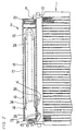
- Fig. 2 is a sectional view showing an inside state of the receiver tank 2.
- Fig. 2 shows that the receiver tank 2 is a vertically extended airtight container which is mainly formed of a double tube consisting of an inner tube 16 and an outer tube 17.
- the outer tube 17 is formed into the shape of a straight tube having a predetermined diameter and a length shorter by a predetermined amount than the header pipes 6, 7.
- the inner tube 16 is formed at its bottom an expanded portion 18 to expand toward the outer tube 17, and the expanded portion 18 is formed to have an outer diameter corresponding to the inner diameter of the outer tube 17. And the section above the expanded portion 18 of the inner tube 16 is formed to have a diameter which is one size smaller than the inner diameter of the outer tube 17.
- the outer tube 17 is formed of a plate clad with a brazing material and having a predetermined size by pressing or the like into a cylinder.
- the inner tube 16 of this embodiment is completely housed in the outer tube 17, and a refrigerant is flowed along the inside and outside of the inner tube, so that it is sufficient by providing only the outer tube 17 with the performance of a pressure-resistant tube. Therefore, the inner tube 16 is not required to have a very high pressure resistance, so that the aforementioned clad tube, an aluminum material, resin or the like can be used for the inner tube 16.
- the expanded portion 18 of the inner tube 16 is forced to be pressure contacted with the inner wall of the outer tube 17 so to form a double tube structure.
- the section above the expanded portion 18 of the inner tube is formed to have a diameter which is one size smaller than the inner diameter of the outer tube 17 to form a passage 19 between the outer tube 17 and the inner tube 16.
- the inner tube 16 and the outer tube 17 are formed to mutually communicate at an upper portion of the receiver tank 2, and openings at the top and bottom ends of the outer tube 17 are sealed with sealing members 20, 21.
- a filter member 22 having a filtering function is disposed within the inner tube 16, and a jacket body 23 containing a desiccant is held by the filter member 22.
- An inlet port 24 communicating with the passage 19 is formed on the outer tube 17, and an outlet port 25 is formed on the expanded portion 18 to communicate the outer tube 17 with the inner tube 16.
- the inlet port 24 is communicated with the outlet communication hole 14 formed on the header pipe 6 by a joint member 26.
- the outlet port 25 is communicated with the inlet communication hole 15 formed on the header pipe 6 by a joint member 27.
- the receiver tank 2 By configuring the receiver tank 2 as described above, it is provided with the double tube structure in which the inner tube 16 and the outer tube 17 are mutually communicated at the top of the receiver tank 2 but not communicated at the bottom.
- Reference numeral 40 in Fig. 2 is a fusible plug which opens under a predetermined pressure and at a predetermined temperature. In case of an increase of an abnormal pressure in a cooling cycle including the receiver tank 2, the pressure is externally released by this plug to prevent the receiver tank 2, piping and the like from being damaged.
- the inner tube 16 is kept not to tilt within the outer tube 17 because the expanded portion 18 is kept in contact with the inner wall of the outer tube 17.
- this embodiment is configured so that the heat-exchanging medium flows into the divided chamber constituting a given flow path within the layered heat exchanger can be taken in and returned to the same divided chamber.
- the heat-exchanging medium in a state of two phases of gas and liquid is taken into the receiver tank 2 from the outlet communication hole 14 of the header pipe 6 through the inlet port 24, and the heat-exchanging medium in a mixture state of two phases of gas and liquid is flowed to rise along the passage 19.
- the up-flowing heat-exchanging medium is separated into gas and liquid at the top communication portion of the outer tube 17 and the inner tube 16, and the separated liquid-drops flow into the inner tube 16.
- the heat-exchanging medium in the form of liquid-drops flowed down into the inner tube 16 is thoroughly liquefied therein by means of the filter member 22 and the desiccant in the jacket body 23 and stored in the lower end portion of the inner tube 16.
- the separated medium in the gas phase tends to stay at a higher portion within the receiver tank 2 and is hardly discharged from the receiver tank 2 because the receiver tank 2 is formed in the upright long shape.
- the liquid refrigerant in the single liquid phase is flowed from the bottom of the inner tube 16 into the header pipe 6 again through the outlet port 25 and the inlet communication hole 15 without being mixed with the heat-exchanging medium in the two-phase state of gas and liquid flowed in from the header pipe 6, so to be circulated in the cooling cycle.
- the receiver tank 2 is formed to have the double tube structure in the non-communicative state at the bottom, the heat-exchanging medium in a mixed state of the two phases of gas and liquid flows upwardly between the inner tube 16 and the outer tube 17, and only the liquid phase can be flowed downward as liquid drops into the inner tube 16, so that it can be stored in the bottom portion of the inner tube without being mixed with the gas medium.
- a refrigerant condensing effect of the heat-exchanging medium can be improved.
- the liquid refrigerant stored in the lower portion of the inner tube is circulated again in the cooling cycle by flowing through the outlet port of the receiver tank 2 and the outlet communication hole of the header pipe, so that a circulating amount of the liquid refrigerant does not decrease, and the cooling performance can be prevented from lowering. And, the heat-exchanging medium is circulated in the cooling cycle in a clean state free from water, a foreign substance and the like by flowing through the receiver tank.
- Fig. 3 is a plan view of the heat exchanger 1 and the receiver tank 2.
- Fig. 3 shows that the header pipe 6 and the receiver tank 2 are mutually connected by means of the joint members 26, 27 with the inlet port 24 and the outlet port 25 of the receiver tank 2 aligned with the outlet and inlet communication holes 14, 15 formed on the header pipe 6, so that the receiver tank 2 can be mounted at a give angle a on the header pipe 6. And, the heat-exchanging performance can be retained without decreasing a front area of the heat exchanger 1, and its flexibility of mounting on a vehicle body can be improved.
- Fig. 4 and Fig. 5 are partial sectional views showing another embodiment of the receiver tank having the double tube structure.
- Fig. 4 shows that an outer tube 29 of the receiver tank of this embodiment is formed to have an internally swelled portion 30 at its lower end portion so to have a thick wall toward the inner tube, and a shoulder section 31 for supporting the bottom end of the inner tube 28 is formed at an upper part of the swelled portion 30.
- the swelled portion 30 and the shoulder section 31 of the outer tube 29 are formed to be thick by cold forging so to maintain a material strength.
- the inner tube 28 is formed to have a diameter one size smaller than the inner diameter of the outer tube 29.
- the inner diameter of the swelled portion 30 of the outer tube 29 has a size substantially the same as the inner diameter of the inner tube 28.
- the shoulder section 31 formed at the upper part of the swelled portion 30 is formed to have an inner diameter slightly smaller than the outer diameter of the inner tube 28.
- An inlet port 33 is formed at a position above the shoulder section 31 of the outer tube 29, and an outlet port 34 is formed on the swelled portion 30 of the outer tube 29.
- the inlet port 33 is communicated with the outlet communication hole 14 of the header pipe 6 by means of an unillustrated joint member, and the outlet port 34 is communicated with the inlet communication hole 15 of the header pipe 6 by means of an unillustrated joint member.
- the heat-exchanging medium flows from the outlet communication hole 14 of the header pipe 6 into the receiver tank through the inlet port 33. After flowing through the passage 32, the medium flows from the upper communication portion into the inner tube 28 and separated into two phases of gas and liquid by an unillustrated filter, desiccant and the like. The separated liquid refrigerant is stored in the lower end portion of the inner tube 28. Then, the liquid refrigerant flows from the inner tube 28 to the header pipe 6 through the outlet port 34 and the inlet communication hole 15 without being mixed with the heat-exchanging medium having the two-phase state of gas and liquid flowed from the header pipe, then circulated again in the cooling cycle of the heat exchanger.
- the receiver tank when the receiver tank is formed to have the double tube structure with the inner tube and the outer tube sealed at the bottoms, the separated liquid refrigerant is stored in the inner tube without being mixed again with the two phases of gas and liquid. Therefore, the refrigerant condensing effect can be improved by a simple structure.
- the inner tube can be formed to have a simple shape and its manufacture can be facilitated because the inner tube having the straight shape can be connected to fit the shoulder portion formed on the outer tube.
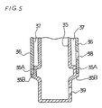
- Fig. 5 is a partial sectional view showing the lower end portion of the double tube structure of the receiver tank similar to Fig. 4.
- Fig. 5 shows that the receiver tank of this embodiment consists of an inner tube 35 and an outer tube 36, and two shoulder portions 35A, 35B are formed at a lower part of the inner tube to protrude toward the outer tube 36.
- the first shoulder portion 35A is formed to protrude toward the outer tube 36 so to have the same diameter as the inner diameter of the outer tube 36.
- the second shoulder portion 35B having the same diameter as the outer diameter of the outer tube 36 is formed at the lower part of the first shoulder portion 35A to protrude toward the outer tube.
- the inner tube 35 is formed to have a diameter one size smaller than the outer tube 36 excluding the shoulder portions 35A, 35B.
- An inlet port 38 is formed on the outer tube 36 so to communicate with the outlet communication hole 14 of the header pipe 6, and an outlet port 39 is formed on the inner tube 35 at a position lower than the shoulder portions 35A, 35B so to communicate with the inlet communication hole 15 of the header pipe 6.
- the inlet port 38 is connected to the outlet communication hole 14 of the header pipe 6 by an unillustrated joint member, and the outlet port 39 is connected to the inlet communication hole 15 by an unillustrated joint member.
- the heat-exchanging medium in the two phases of gas and liquid flowing into the receiver tank flows through a passage 37 formed between the outer tube 36 and the inner tube 35 and flows from the upper communicated portion into the inner tube 35.
- the heat-exchanging medium is separated into two phases of gas and liquid by an unillustrated filter, desiccant and the like, and the separated liquid refrigerant is stored in the lower end portion of the inner tube. Since the receiver tank is formed to have the double tube structure without communicating its bottom portion, the liquid refrigerant stored in the lower portion of the inner tube is not mixed with the gas medium or the like and can flow into the header pipe 6 to be circulated again in the cooling cycle.
- the outer tube in the shape of a straight tube is connected to fit the shoulder portion formed on the inner tube, the shape of the outer tube can be simplified, and the manufacture can be facilitated.
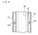
- Fig. 6 and Fig. 7 are partial sectional views showing another embodiments of receiver tanks having the structure for prevention of the inner tube from tilting, respectively.
- the outer tube 17 of the receiver tank shown in Fig. 6 has projections 17a, 17a formed at given positions on the side wall of the outer tube 17 so to protrude toward the inner tube 16, thereby holding the inner tube 16 by the projections 17a, 17a.
- the projections 17a, 17a are formed at positions occupying three points on the circumference intersecting at least at right angles with a longitudinal axis of the outer tube 17. And, these projections 17a, 17a are formed to spot-protrude toward the inner tube, and an inner diameter formed by the leading ends of the respective projections 17a, 17a is determined to be the same to or slightly larger than the outer diameter of the inner tube 16.
- the projections 17a serve to hold the inner tube 16 within the outer tube 17 when the outer tube 17 and the inner tube 16 are brazed, so that the inner tube 16 can be held by the projections 17a not to tilt in the outer tube 17 and brazed.
- the double tube structure having a predetermined passage formed can be formed.
- the inner tube 16 can be held from the direction of the outer periphery by the projections 17a.
- the inner tube 16 and the outer tube 17 are held at the bottom end.
- the inner tube 16 can be held without tilting, and the inner tube 16 and the outer tube 17 can be brazed with a predetermined passage formed therebetween. And, the inner tube 16 can be held and the stable double tube structure can be formed without clogging the passage 19 formed between the inner tube 16 and the outer tube 17 because the inner tube 16 is held by the projections 17a.
- the projections 17a are formed at positions occupying the circumference intersecting at right angles with the longitudinal axis of the outer tube 17. But, it is not exclusive, and the projections may be formed flexibly in view of the facilitation of manufacturing, etc. by, e.g., alternately disposing in the longitudinal direction, if the inner tube can be held stably.
- the inner tube 16 when the inner tube 16 is inserted into the outer tube 17, the inner tube 16 has its circumference held by the projections 17a, 17a.
- the inner tube 16 is stably held within the outer tube 17, and the double tube structure can be maintained without tilting the inner tube 16 by oscillation or the like.
- the passage formed between the outer tube 17 and the inner tube 16 is stably retained.
- the receiver tank shown in Fig. 7 is configured to partly protrude the side wall of the inner tube 16 toward the outer tube 17 to form projections 16a, 16a so to hold the inner tube 16 within the outer tube 17 by these projections 16a, 16a.
- projections 16a, 16a are formed at positions occupying three points on the circumference intersecting at least at right angles with a longitudinal axis of the inner tube 16. And, these projections 16a, 16a are formed to spot-protrude toward the outer tube, and an outer diameter formed by the leading ends of the respective projections 16a, 16a is determined to be the same to or slightly smaller than the inner diameter of the outer tube 17.
- the double tube structure can be configured stably without tilting the inner tube 16 within the outer tube 17.
- the positions where the projections 16a, 16a of this embodiment are formed can be determined relatively freely so long as the inner tube 16 can be held stably. And, this arrangement may be combined with the aforesaid embodiment as required.
- the projections are partly formed on the side wall of the inner tube or the outer tube to protrude toward the outer tube or the inner tube, the inner tube is supported by the projections within the outer tube, so that the inner tube can be prevented from tilting and the stable double tube structure can be formed.
- only the inner tube may be modified to integrally form the projections on the inner tube, so that a pressure resistance of the outer tube against the inner pressure can be secured without deteriorating the strength of the outer tube.
- Fig. 8 shows an embodiment of using a joint member at a lower part of the receiver tank having the double tube structure
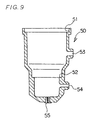
- Fig. 9 shows the joint member.
- a joint member 50 has a shoulder portion 51, to which an outer tube 41 is fitted, formed at an upper portion, a shoulder portion 52, to which an inner tube 42 is fitted, formed at a lower portion, an inlet port 53 formed between the shoulder portions 51 and 52, an outlet port 54 at a lower end portion of the lower shoulder portion 52, and a fusible plug 55 at the bottom end.
- the heat-exchanging medium entering a passage 43 formed between the inner and outer tubes 41 and 42 through the inlet port 53 flows into an interior 44 of the inner tube 42 from the upper communication portion and separated into two phases of gas and liquid by an unillustrated filter, desiccant and the like. And, the separated liquid refrigerant is stored in a lower end portion of the inner tube 42. Then, the liquid refrigerant flows from the interior of the inner tube 42 into the header pipe through the outlet port 54 without mixing with the heat-exchanging medium having a mixture of two phases of gas and liquid introduced from the header pipe and again circulated in the cooling cycle of the heat exchanger.
- the receiver tank is formed to have the double tube structure which has the inner tube and the outer tube hermetically sealed at the bottom, the separated liquid refrigerant is not mixed with the two phases of gas and liquid again and stored within the inner tube, so that the refrigerant condensing effect can be improved by a simple structure.
- the joint member is used in this embodiment, the shapes of the inner and outer tubes can be simplified. As a result, the manufacture can be further facilitated.
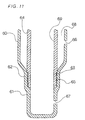
- Fig. 10 shows a sectional view of the bottom portion of the two tubes configuring the receiver tank, an outer tube 60 and an inner tube 64 configuring the receiver tank before being assembled.
- a contraction portion 61 having a diameter smaller than that of the outer tube 60 is formed at a lower end portion of the outer tube 60, and a shoulder portion 62 is formed at an upper portion of the contraction portion 61 to hold the outer periphery of the inner tube 64 by the inner periphery of the shoulder portion 62.
- an inlet port 66 is formed on the outer tube 60 for introducing the heat-exchanging medium
- an outlet port 67 is formed on the contraction portion 61 for discharging the heat-exchanging medium.
- the pressure resistance of the receiver tank can be improved by the above-described embodiment in which the contraction portion 61 is formed on the outer tube of the double tube structure of the receiver tank, and a pressure load applied to the bottom is eased by the contraction portion 61.
- the inner tube 64 configuring the double tube of this embodiment is formed to have the outer diameter slightly larger than the inner diameter of the shoulder portion 62 of the outer tube 60. And, a portion of the outer periphery of the inner tube 64, which is brought into contact with the inner periphery of the outer tube 60, is formed to have a knurled portion 65 by cutting or the like.
- the inner tube 64 is inserted in the direction indicated by an arrow and held by the shoulder portion 62 of the outer tube 60 with high airtightness because the knurled portion 65 formed on the outer periphery of the inner tube 64 is pressure contacted to the inner periphery of the outer tube 60.
- the heat-exchanging medium which enters the inlet port 66 to flow through a passage 68 formed between the inner and outer tubes 60 and 64, is introduced from the top communication part into an interior 69 of the inner tube 64 and separated into two phases of gas and liquid by an unillustrated filter, desiccant and the like. And, the separated liquid refrigerant is stored in a lower end portion of the contraction portion 61 of the outer tube 60. Then, the liquid refrigerant flows from the contraction portion 61 of the outer tube 60 into the header pipe through the outlet port 67 and again circulated in the cooling cycle of the heat exchanger.
- the outer diameter of the inner tube 64 held by the shoulder portion 62 of the outer tube 60 is formed to be slightly larger than the inner diameter of the shoulder portion 62, and the knurled portion 65 is formed on the outer periphery of the inner tube 64, so that the inner tube 64 is firmly contacted to the shoulder portion 62 of the outer tube 60, and the heat-exchanging medium in a mixed state of the two phases of gas and liquid can be prevented from being mixed with the liquid medium again.
- a knurled portion 63 is formed on the inner surface of the shoulder portion 62 of the outer tube 60 so to engage with the knurled portion 65 of the inner tube 64.
- airtightness can be improved by the engagement between the knurled portions 63 and 65.
- the knurled portion may be formed on any or all of the joint member, the inner tube and the outer tube so to firmly join their joint portions.
- the joint portions are tightly connected, and airtightness is further improved.
- the present invention proposes the receiver tank having the double tube structure so that the refrigerant condensing effect is improved, and the flexibility of mounting it on a vehicle body is enhanced.
- the present invention is particularly suitable for the cooling cycle of automobiles that require relatively sever mounting conditions.
Landscapes
- Engineering & Computer Science (AREA)
- Physics & Mathematics (AREA)
- Mechanical Engineering (AREA)
- Thermal Sciences (AREA)
- General Engineering & Computer Science (AREA)
- Heat-Exchange Devices With Radiators And Conduit Assemblies (AREA)
- Air-Conditioning For Vehicles (AREA)
- Details Of Heat-Exchange And Heat-Transfer (AREA)
Claims (10)
- Sammelbehälter (2), der in einem luftdichten Behälter mit einer Einlassöffnung (24) und einer Auslassöffnung (25) für ein Kältemittel ausgebildet ist, wobei das in einem gas-flüssig Mischzustand eingeführte Kältemittel aufgetrennt wird und das getrennte flüssige Kältemittel darin gespeichert und daraus ausgegeben wird, um es kontinuierlich einzuspeisen, dadurch gekennzeichnet, dass:der luftdichte Behälter als eine Doppelröhre aus einer inneren (16) und einer äußeren (17) Röhre ausgebildet ist, deren obere Enden miteinander in Verbindung stehen, aber deren unteren Enden nicht;die Einlassöffnung (24) die äußere Röhre (17) durchdringt, um mit einem Kanal, der zwischen den zwei Röhren ausgebildet ist, in Verbindung zu stehen;die Auslassöffnung an einem unteren Endabschnitt der Doppelröhre ausgebildet ist, um die äußere und innere Röhre zu durchdringen und auch um mit dem Inneren der inneren Röhre in Verbindung zu stehen, unddas durch die Einlassöffnung eingetretene Kältemittel in dem Raum (19) zwischen der äußeren Röhre und der inneren Röhre nach oben aufsteigt, um von dem oberen Ende der in Verbindung stehenden Doppelröhre in die innere Röhre einzuströmen, innerhalb der inneren Röhre nach unten zuströmen, um sich in einem unteren Endabschnitt der inneren Röhre anzusammeln und dann durch die Auslassöffnung (25), die an dem unteren Ende der inneren Röhre ausgebildet ist, ausgegeben zu werden.
- Sammelbehälter nach Anspruch 1, wobei ein Schulterabschnitt an einem unteren inneren Abschnitt der äußeren Röhre ausgebildet ist, das untere Ende der inneren Röhre mit dem Schulterabschnitt verbunden und abgedichtet ist, und wobei die Auslassöffnung an einem unteren Endabschnitt der äußeren Röhre ausgebildet ist.
- Sammelbehälter nach Anspruch 1, wobei ein Schulterabschnitt an einem unteren, äußeren Abschnitt der inneren Röhre ausgebildet ist, das untere Ende der äußeren Röhre mit dem Schulterabschnitt verbunden und abgedichtet ist, und wobei die Auslassöffnung in der inneren Röhre an einem Abschnitt davon unterhalb des Schulterabschnitts ausgebildet ist.
- Sammelbehälter nach Anspruch 1, wobei Vorsprünge an der äußeren Röhre des Doppelrohrs ausgebildet sind, um in Richtung der inneren Röhre vorzuragen, um so mit der inneren Röhre in Kontakt zu kommen.
- Sammelbehälter nach Anspruch 1, wobei Vorsprünge an der inneren Röhre der zwei Röhren ausgebildet sind, um in Richtung der anderen Röhre vorzustehen, um so mit der anderen Röhre in Kontakt zu kommen.
- Sammelbehälter nach Anspruch 1, wobei ein Verbindungselement, welches die innere und äußere Röhre hält und eine Einlassöffnung und eine Auslassöffnung aufweist, an einem unteren Endabschnitt der Doppelröhre angeordnet ist.
- Sammelbehälter nach Anspruch 1, wobei ein verengter Abschnitt, der kleiner als der äußere Durchmesser der äußeren Röhre ist, an einem unteren Endabschnitt der äußeren Röhre der Doppelröhre ausgebildet ist und ein Schulterabschnitt an dem inneren Umfang des verengten Abschnitts ausgebildet ist, um mit dem Ende der inneren Röhre in Eingriff zu kommen.
- Sammelbehälter nach Anspruch 2, 3 oder 7, wobei ein Kontaktabschnitt zwischen der inneren Röhre und der äußeren Röhre in einem unter Druck stehenden Kontaktzustand ist und ein gerändelter Abschnitt entweder auf der inneren Röhre oder der äußeren Röhre an dem Kontaktabschnitt oder beidem ausgebildet ist.
- Sammelbehälter nach Anspruch 6, wobei das Verbindungselement in einem Kontaktabschnitt der inneren und äußeren Röhre, die durch das Verbindungselement gehalten werden, in einem unter Druck stehenden Kontaktzustand ist, und der gerändelte Abschnitt in dem Kontaktabschnitt auf dem Verbindungselement, der inneren Röhre oder der äußeren Röhre oder allen ausgebildet ist.
- Sammelbehälter nach Anspruch 1, wobei das von dem oberen Ende der Doppelröhre in die innere Röhre eintretende Kältemittel die innere Röhre nach unten strömt und in gasförmiges und flüssiges Kältemittel aufgetrennt wird, welches getrennte flüssige Kältemittel in einem unteren Endabschnitt der inneren Röhre gesammelt wird und nur eine erforderliche Menge des flüssigen Kältemittels durch die Auslassöffnung ausgegeben wird.
Applications Claiming Priority (5)
| Application Number | Priority Date | Filing Date | Title |
|---|---|---|---|
| JP20150497 | 1997-07-28 | ||
| JP20150497 | 1997-07-28 | ||
| JP10811598A JP3801348B2 (ja) | 1997-07-28 | 1998-04-17 | レシーバタンク |
| JP10811598 | 1998-04-17 | ||
| PCT/JP1998/003338 WO1999005464A1 (en) | 1997-07-28 | 1998-07-27 | Receiver tank |
Publications (3)
| Publication Number | Publication Date |
|---|---|
| EP1006323A1 EP1006323A1 (de) | 2000-06-07 |
| EP1006323A4 EP1006323A4 (de) | 2000-08-23 |
| EP1006323B1 true EP1006323B1 (de) | 2003-09-24 |
Family
ID=26448073
Family Applications (1)
| Application Number | Title | Priority Date | Filing Date |
|---|---|---|---|
| EP98933946A Expired - Lifetime EP1006323B1 (de) | 1997-07-28 | 1998-07-27 | Sammelbehälter |
Country Status (5)
| Country | Link |
|---|---|
| US (1) | US6295832B1 (de) |
| EP (1) | EP1006323B1 (de) |
| JP (1) | JP3801348B2 (de) |
| DE (1) | DE69818488T2 (de) |
| WO (1) | WO1999005464A1 (de) |
Cited By (1)
| Publication number | Priority date | Publication date | Assignee | Title |
|---|---|---|---|---|
| US7043936B2 (en) | 2001-10-09 | 2006-05-16 | Behr Gmbh & Co. | Refrigerant condenser |
Families Citing this family (26)
| Publication number | Priority date | Publication date | Assignee | Title |
|---|---|---|---|---|
| EP1202007A1 (de) * | 2000-10-25 | 2002-05-02 | Skg Italiana Spa | Verflüssiger und Trockner |
| JP2002263055A (ja) * | 2001-03-12 | 2002-09-17 | Olympus Optical Co Ltd | 内視鏡先端フード |
| JP2003083698A (ja) * | 2001-09-07 | 2003-03-19 | Sanden Corp | 熱交換器および熱交換器の製造方法 |
| JP4608834B2 (ja) * | 2001-09-18 | 2011-01-12 | 株式会社デンソー | 冷凍サイクル装置 |
| TWI280340B (en) * | 2002-02-20 | 2007-05-01 | Showa Denko Kk | Heat exchanger with receiver tank, receiver tank connecting member, receiver tank mounting structure of heat exchanger and refrigeration system |
| WO2003098130A1 (en) * | 2002-05-22 | 2003-11-27 | Nikkei Heat Exchanger Company, Ltd. | Heat exchanger with liquid receiver |
| KR100450122B1 (ko) * | 2002-05-30 | 2004-09-30 | 모딘코리아 유한회사 | 에어콘용 서브쿨 콘덴서 |
| KR100450123B1 (ko) * | 2002-05-30 | 2004-09-30 | 모딘코리아 유한회사 | 에어콘용 서브쿨 콘덴서 |
| KR100730567B1 (ko) * | 2002-07-09 | 2007-06-20 | 한라공조주식회사 | 공조장치용 리시버 드라이어 및 그 제작방법 |
| DE10251777A1 (de) * | 2002-11-05 | 2004-05-19 | Behr Gmbh & Co. | Sammelbehälter, Wärmetauscher und Kältemittelkreislauf |
| US6694773B1 (en) * | 2003-01-29 | 2004-02-24 | Calsonickansei North America, Inc. | Condenser system with nondetachably coupled receiver |
| US20050066685A1 (en) * | 2003-09-30 | 2005-03-31 | Delphi Technologies, Inc. | Pre braze installed desiccant assembly for automotive condenser with integral receiver |
| US7003978B2 (en) | 2003-12-12 | 2006-02-28 | Calsonickansei North America, Inc. | Service cartridge for a receiver in a condenser system |
| US6981389B2 (en) * | 2003-12-12 | 2006-01-03 | Calsonickansei North America, Inc. | Receiver and service cartridge for a condenser system |
| DE102004022714A1 (de) * | 2004-05-05 | 2005-12-15 | Behr Gmbh & Co. Kg | Kondensator für eine Klimaanlage, insbesondere für ein Kraftfahrzeug |
| KR101297061B1 (ko) | 2004-07-02 | 2013-08-19 | 베링거 인겔하임 인터내셔날 게엠베하 | 추진제로서 tg 227 ea 또는 tg 134 a를함유하는 에어로졸 현탁액 제형 |
| US20060070724A1 (en) * | 2004-10-06 | 2006-04-06 | Visteon Global Technologies, Inc. | Integrated receiver dryer sleeve |
| JP2007132589A (ja) * | 2005-11-10 | 2007-05-31 | Valeo Thermal Systems Japan Corp | 熱交換器 |
| JP5593084B2 (ja) * | 2009-07-29 | 2014-09-17 | 株式会社ケーヒン・サーマル・テクノロジー | 熱交換器 |
| JP5454007B2 (ja) * | 2009-08-27 | 2014-03-26 | 株式会社アドヴィックス | 車両用液圧ブレーキの制御ユニット |
| JP5624299B2 (ja) * | 2009-10-05 | 2014-11-12 | 株式会社不二工機 | レシーバドライヤ |
| USD655728S1 (en) * | 2010-04-05 | 2012-03-13 | Showa Denko K.K. | Condenser |
| US9612046B2 (en) * | 2012-12-14 | 2017-04-04 | Mahle International Gmbh | Sub-cooled condenser having a receiver tank with a refrigerant diverter for improved filling efficiency |
| US20150041414A1 (en) * | 2013-08-09 | 2015-02-12 | Ledwell & Son Enterprises, Inc. | Hydraulic fluid cooler and filter |
| WO2015128807A2 (en) * | 2014-02-26 | 2015-09-03 | Denso Thermal Systems S.P.A. | Horizontal condenser with coolant accumulator |
| DE102014220401A1 (de) * | 2014-10-08 | 2016-04-14 | Mahle International Gmbh | Kältemittelbehälter für eine Kälteanlage |
Family Cites Families (17)
| Publication number | Priority date | Publication date | Assignee | Title |
|---|---|---|---|---|
| JPH0338605Y2 (de) * | 1985-09-20 | 1991-08-14 | ||
| JPH0539408Y2 (de) * | 1988-10-22 | 1993-10-06 | ||
| JPH0823199B2 (ja) | 1989-01-30 | 1996-03-06 | 株式会社平井技研 | 軒先装置 |
| JPH07122533B2 (ja) | 1989-04-05 | 1995-12-25 | 株式会社日立製作所 | 凝縮器 |
| DE3914715A1 (de) | 1989-05-04 | 1990-11-08 | Bayer Ag | Feinverteilte polyarylensulfide enthaltende polyamidformmassen |
| JPH036262U (de) * | 1989-06-06 | 1991-01-22 | ||
| JP3081941B2 (ja) * | 1990-08-23 | 2000-08-28 | 株式会社ゼクセル | レシーバタンク一体型コンデンサ |
| JP3204404B2 (ja) | 1991-04-22 | 2001-09-04 | 株式会社デンソー | 受液器一体型凝縮器 |
| JPH0546511A (ja) | 1991-08-13 | 1993-02-26 | Kobe Nippon Denki Software Kk | 通信制御装置 |
| JPH05306857A (ja) | 1992-03-04 | 1993-11-19 | Nippondenso Co Ltd | 冷凍装置の受液器 |
| DE4402927B4 (de) * | 1994-02-01 | 2008-02-14 | Behr Gmbh & Co. Kg | Kondensator für eine Klimaanlage eines Fahrzeuges |
| DE4421834A1 (de) * | 1994-06-22 | 1996-01-04 | Behr Gmbh & Co | Einsatz für einen Kondensator einer Klimaanlage eines Fahrzeuges |
| FR2735851B1 (fr) * | 1995-06-23 | 1997-08-01 | Valeo Thermique Moteur Sa | Condenseur a reservoir integre pour installation de climatisation de vehicule automobile |
| JPH09170854A (ja) | 1995-10-18 | 1997-06-30 | Calsonic Corp | リキッドタンクを備えたコンデンサ |
| DE19748662A1 (de) * | 1996-11-08 | 1998-05-14 | Zexel Corp | Flüssigkeitsbehälter |
| DE19712714A1 (de) * | 1997-03-26 | 1998-10-01 | Behr Gmbh & Co | Einsatz für ein Sammlerprofil eines Kondensators |
| US6125651A (en) * | 1998-03-23 | 2000-10-03 | Automotive Fluid Systems, Inc. | Air-conditioning system accumulator and method of making same |
-
1998
- 1998-04-17 JP JP10811598A patent/JP3801348B2/ja not_active Expired - Fee Related
- 1998-07-27 WO PCT/JP1998/003338 patent/WO1999005464A1/ja not_active Ceased
- 1998-07-27 DE DE69818488T patent/DE69818488T2/de not_active Expired - Fee Related
- 1998-07-27 EP EP98933946A patent/EP1006323B1/de not_active Expired - Lifetime
- 1998-07-27 US US09/463,322 patent/US6295832B1/en not_active Expired - Fee Related
Cited By (1)
| Publication number | Priority date | Publication date | Assignee | Title |
|---|---|---|---|---|
| US7043936B2 (en) | 2001-10-09 | 2006-05-16 | Behr Gmbh & Co. | Refrigerant condenser |
Also Published As
| Publication number | Publication date |
|---|---|
| JPH11101532A (ja) | 1999-04-13 |
| EP1006323A1 (de) | 2000-06-07 |
| DE69818488D1 (de) | 2003-10-30 |
| US6295832B1 (en) | 2001-10-02 |
| WO1999005464A1 (en) | 1999-02-04 |
| DE69818488T2 (de) | 2004-07-22 |
| JP3801348B2 (ja) | 2006-07-26 |
| EP1006323A4 (de) | 2000-08-23 |
Similar Documents
| Publication | Publication Date | Title |
|---|---|---|
| EP1006323B1 (de) | Sammelbehälter | |
| EP1884734B1 (de) | Wärmetauscheranordnung mit unterteilten Sammelrohren | |
| US6622517B1 (en) | Condenser assembly having readily varied volumetrics | |
| AU648963B2 (en) | Heat exchanger | |
| CN102706045B (zh) | 冷凝器 | |
| KR100265479B1 (ko) | 리시버 및 드라이어 | |
| WO2008050221A2 (en) | Thermal storage device | |
| JP2005513403A (ja) | 特に自動車用の熱交換器 | |
| JP3314237B2 (ja) | レシーバタンク | |
| CA2159143C (en) | Heat exchanger with integral filter/drier cartridge | |
| JP4608277B2 (ja) | 車両用凝縮器と、この凝縮器を含む一体型放熱器凝縮器本体 | |
| EP1359384B1 (de) | Wärmetauscher | |
| CN108709445B (zh) | 保冷热交换器 | |
| JPH102692A (ja) | 熱交換器のブラケット構造 | |
| JP3854381B2 (ja) | 熱交換器の接続構造 | |
| US7918266B2 (en) | Heat exchanger | |
| JP7114831B2 (ja) | 熱交換器用レシーバタンク | |
| CN105299977A (zh) | 用于换热器的接收器、以及装备有接收器的换热器 | |
| JPH1163881A (ja) | 積層型熱交換器 | |
| JP2008267753A (ja) | 熱交換器 | |
| US20030015310A1 (en) | Heat exchanger for a thermal coupling | |
| JPH11325788A (ja) | 熱交換器の接続構造 | |
| EP2110623A1 (de) | Wärmetauscher | |
| KR100538746B1 (ko) | 수액기 | |
| KR200259604Y1 (ko) | 수액기 |
Legal Events
| Date | Code | Title | Description |
|---|---|---|---|
| PUAI | Public reference made under article 153(3) epc to a published international application that has entered the european phase |
Free format text: ORIGINAL CODE: 0009012 |
|
| 17P | Request for examination filed |
Effective date: 20000228 |
|
| AK | Designated contracting states |
Kind code of ref document: A1 Designated state(s): DE FR GB |
|
| A4 | Supplementary search report drawn up and despatched |
Effective date: 20000711 |
|
| AK | Designated contracting states |
Kind code of ref document: A4 Designated state(s): DE FR GB |
|
| RIC1 | Information provided on ipc code assigned before grant |
Free format text: 7F 25B 43/00 A, 7F 28F 9/26 B, 7F 25B 39/04 B |
|
| RAP1 | Party data changed (applicant data changed or rights of an application transferred) |
Owner name: ZEXEL VALEO CLIMATE CONTROL CORPORATION |
|
| GRAH | Despatch of communication of intention to grant a patent |
Free format text: ORIGINAL CODE: EPIDOS IGRA |
|
| GRAH | Despatch of communication of intention to grant a patent |
Free format text: ORIGINAL CODE: EPIDOS IGRA |
|
| GRAA | (expected) grant |
Free format text: ORIGINAL CODE: 0009210 |
|
| AK | Designated contracting states |
Kind code of ref document: B1 Designated state(s): DE FR GB |
|
| REG | Reference to a national code |
Ref country code: GB Ref legal event code: FG4D |
|
| REF | Corresponds to: |
Ref document number: 69818488 Country of ref document: DE Date of ref document: 20031030 Kind code of ref document: P |
|
| ET | Fr: translation filed | ||
| PG25 | Lapsed in a contracting state [announced via postgrant information from national office to epo] |
Ref country code: GB Free format text: LAPSE BECAUSE OF NON-PAYMENT OF DUE FEES Effective date: 20040727 |
|
| PLBE | No opposition filed within time limit |
Free format text: ORIGINAL CODE: 0009261 |
|
| STAA | Information on the status of an ep patent application or granted ep patent |
Free format text: STATUS: NO OPPOSITION FILED WITHIN TIME LIMIT |
|
| 26N | No opposition filed |
Effective date: 20040625 |
|
| GBPC | Gb: european patent ceased through non-payment of renewal fee |
Effective date: 20040727 |
|
| PGFP | Annual fee paid to national office [announced via postgrant information from national office to epo] |
Ref country code: FR Payment date: 20060719 Year of fee payment: 9 |
|
| PGFP | Annual fee paid to national office [announced via postgrant information from national office to epo] |
Ref country code: DE Payment date: 20060720 Year of fee payment: 9 |
|
| PG25 | Lapsed in a contracting state [announced via postgrant information from national office to epo] |
Ref country code: DE Free format text: LAPSE BECAUSE OF NON-PAYMENT OF DUE FEES Effective date: 20080201 |
|
| REG | Reference to a national code |
Ref country code: FR Ref legal event code: ST Effective date: 20080331 |
|
| PG25 | Lapsed in a contracting state [announced via postgrant information from national office to epo] |
Ref country code: FR Free format text: LAPSE BECAUSE OF NON-PAYMENT OF DUE FEES Effective date: 20070731 |