EP1006400A2 - Optische Vorrichtung und Fresnellinsen-Folie - Google Patents
Optische Vorrichtung und Fresnellinsen-Folie Download PDFInfo
- Publication number
- EP1006400A2 EP1006400A2 EP99123273A EP99123273A EP1006400A2 EP 1006400 A2 EP1006400 A2 EP 1006400A2 EP 99123273 A EP99123273 A EP 99123273A EP 99123273 A EP99123273 A EP 99123273A EP 1006400 A2 EP1006400 A2 EP 1006400A2
- Authority
- EP
- European Patent Office
- Prior art keywords
- fresnel lens
- rays
- diffraction grating
- light
- wavelength dependency
- Prior art date
- Legal status (The legal status is an assumption and is not a legal conclusion. Google has not performed a legal analysis and makes no representation as to the accuracy of the status listed.)
- Withdrawn
Links
Images


Classifications
-
- G—PHYSICS
- G02—OPTICS
- G02B—OPTICAL ELEMENTS, SYSTEMS OR APPARATUS
- G02B5/00—Optical elements other than lenses
- G02B5/18—Diffraction gratings
- G02B5/1814—Diffraction gratings structurally combined with one or more further optical elements, e.g. lenses, mirrors, prisms or other diffraction gratings
-
- G—PHYSICS
- G02—OPTICS
- G02B—OPTICAL ELEMENTS, SYSTEMS OR APPARATUS
- G02B27/00—Optical systems or apparatus not provided for by any of the groups G02B1/00 - G02B26/00, G02B30/00
- G02B27/42—Diffraction optics, i.e. systems including a diffractive element being designed for providing a diffractive effect
- G02B27/4205—Diffraction optics, i.e. systems including a diffractive element being designed for providing a diffractive effect having a diffractive optical element [DOE] contributing to image formation, e.g. whereby modulation transfer function MTF or optical aberrations are relevant
- G02B27/4211—Diffraction optics, i.e. systems including a diffractive element being designed for providing a diffractive effect having a diffractive optical element [DOE] contributing to image formation, e.g. whereby modulation transfer function MTF or optical aberrations are relevant correcting chromatic aberrations
-
- G—PHYSICS
- G02—OPTICS
- G02B—OPTICAL ELEMENTS, SYSTEMS OR APPARATUS
- G02B3/00—Simple or compound lenses
- G02B3/02—Simple or compound lenses with non-spherical faces
- G02B3/08—Simple or compound lenses with non-spherical faces with discontinuous faces, e.g. Fresnel lens
-
- G—PHYSICS
- G03—PHOTOGRAPHY; CINEMATOGRAPHY; ANALOGOUS TECHNIQUES USING WAVES OTHER THAN OPTICAL WAVES; ELECTROGRAPHY; HOLOGRAPHY
- G03B—APPARATUS OR ARRANGEMENTS FOR TAKING PHOTOGRAPHS OR FOR PROJECTING OR VIEWING THEM; APPARATUS OR ARRANGEMENTS EMPLOYING ANALOGOUS TECHNIQUES USING WAVES OTHER THAN OPTICAL WAVES; ACCESSORIES THEREFOR
- G03B21/00—Projectors or projection-type viewers; Accessories therefor
- G03B21/54—Accessories
- G03B21/56—Projection screens
- G03B21/60—Projection screens characterised by the nature of the surface
- G03B21/62—Translucent screens
- G03B21/625—Lenticular translucent screens
Definitions
- the present invention relates to an optical device and a Fresnel lens sheet comprising it.
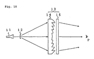
- Fig. 10 is a schematic view showing the outline of the constitution of a conventional rear projection display.
- the conventional rear projection display comprises a projection tube 11 which projects an optical image, a projection lens 12 which magnifies the optical image from the projection tube 11, and a rear projection screen 13 which forms thereon the optical image having been magnified through the projection lens 12.
- a person P views the optical image having been projected, magnified and formed on the rear projection screen 13.
- the screen 13 has a two-sheet structure composed of a Fresnel lens sheet 14 which gathers the beams of light from the projection tube 11 toward the viewer, and a lenticular lens sheet 15 which disperses the light having passed through the Fresnel lens sheet 14 in the direction horizontal to the screen (that is, in the direction of the width of the screen) and in the direction vertical thereto (that is, in the direction of the height of the screen) at a predetermined angle in a suitable ratio to thereby enlarge the angle of visibility to be in a predetermined range.
- the projection lens 12 and the screen 13 are desired to be so disposed that the distance therebetween is shorter so as to reduce the thickness of the display. It is also desired to increase the luminance around the peripheral area of the screen.
- the Fresnel angle in the peripheral area of the Fresnel lens sheet 14 must be enlarged.
- the refractive index of the material that forms the Fresnel lens surface of the Fresnel lens sheet has wavelength dependency. Therefore, the angle of light passing through the Fresnel lens shall vary, depending on the wavelength of the light.
- the present inventors have completed the present invention with its object to provide an optical device through which the angle of light passing and going out has little wavelength dependency and which is well applicable to Fresnel lenses with little coloration of light passing through it.
- the optical device of the invention to solve the problem noted above has a diffraction grating formed on one surface and capable of diffracting rays of light incident thereon, and has a retracting member formed on the other surface opposite to the diffraction grating and capable of retracting the diffracted rays of light from the diffraction grating to make the refracted rays of light go out of it, in which the wavelength dependency of the diffractive angle of the main rays diffracted by the diffraction grating compensates for the wavelength dependency of the refractive angle thereof refracted by the retracting member, or that is, the former wavelength dependency is opposite to and cancels out the latter one.
- optical device of the invention to solve the problem noted above has a refracting member formed on one surface and capable of retracting rays of light incident thereon, and has a diffraction grating formed on the other surface opposite to the refracting member and capable of diffracting the refracted rays of light from the retracting member to make the diffracted rays of light go out of it, in which the wavelength dependency of the diffractive angle of the main rays diffracted by the diffraction grating compensates for the wavelength dependency of the refractive angle thereof refracted by the refracting member, or that is, the former wavelength dependency is opposite to and cancels out the latter one.
- the refracting member may be of a Fresnel lens to give a Fresnel lens sheet.
- the diffraction grating may be formed on the refracting member.
- the optical device of this embodiment of the invention has a refracting member formed on one surface and capable of refracting rays of light incident thereon to give refracted rays of light going out of it, and has a diffraction grating formed on the refracting member, in which the wavelength dependency of the diffractive angle of the main rays diffracted by the diffraction grating compensates for the wavelength dependency of the refractive angle thereof refracted by the refracting member.
- the refracting member may be also of a Fresnel lens to give a Fresnel lens sheet.
- the diffraction grating and the refracting member of, for example, a Fresnel lens may be formed in different sheets.
- the diffraction grating sheet with a diffraction grating capable of diffracting rays of light incident thereon may be combined with the Fresnel lens sheet with a Fresnel lens capable of refracting the diffracted rays of light from the diffraction grating sheet to give refracted rays of light going out of it, in such a manner that the wavelength dependency of the diffractive angle of the main rays diffracted by the diffraction grating compensates for the wavelength dependency of the refractive angle thereof refracted by the Fresnel lens sheet.
- nR, nG and nB of an ordinary Fresnel lens to red light (R), green light (G) and blue light (B), respectively, from a light source are generally in the following order: nR ⁇ nG ⁇ nB
- angles ⁇ R, ⁇ G and ⁇ B of the red light, the green light and the blue light, respectively, going out of the Fresnel lens shall be in the following order: ⁇ R ⁇ ⁇ G ⁇ B
- Fig. 9A showing one model of an ordinary Fresnel lens
- the angles of different rays of light going out of the Fresnel lens vary, depending on the wavelength of each ray.
- the wavelength dependency of rays of light passing through the Fresnel lens causes coloration of the projection screen combined with the Fresnel lens sheet and greatly degrades the quality of images formed on the screen.
- the wavelengths of the incoming red light, green light and blue light represented by ⁇ R, ⁇ G and ⁇ B, respectively, are in the following order: ⁇ R > ⁇ G > ⁇ B Therefore, when m > 0, ⁇ R > ⁇ G > ⁇ B wherein ⁇ R, ⁇ G and ⁇ B indicate the diffractive angles of the red light, the green light and the blue light, respectively.
- the diffraction grating acts on the Fresnel lens in such a manner that the wavelength dependency of the diffractive angles of rays of light passing through the diffraction grating cancels out the wavelength dependency of the refractive angles of those rays of light passing through the Fresnel lens. Therefore, in the illustrated device, the wavelength dependency of the outgoing angles of rays of light going out of the Fresnel lens is thereby canceled to reduce the coloration of image-forming screens.
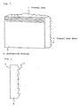
- Fig. 1 is a perspective view showing the outline of a rear projection screen comprising the Fresnel lens sheet of the invention.
- a lenticular lens sheet 1 is disposed on the side of a viewer, and a Fresnel lens sheet 2 is on the side of a projection tube (not shown).
- a diffraction grating 4 is formed on the surface of the Fresnel lens sheet 2 facing a projection tube, while a Fresnel lens 3 is formed on the other surface thereof through which the light having entered it goes out.
- the diffraction grating may be formed concentrically with the Fresnel lens so that the center of the former could be the same as that of the latter, as so illustrated in Fig. 2. However, it is not always necessary to make the center of the diffraction grating the same as that of the Fresnel lens. If desired, the centers of the two may be shifted in some degree, depending on the intended light-collecting capabilities of them. Where the diffraction grating is formed concentrically with the Fresnel lens so that the center of the former could be the same as that of the latter, as in the illustrated case, the rays of light from a projection tube to enter the diffraction grating are so diffracted that they run in the direction of the center of the sheet.
- the Fresnel lens sheet may be produced, for example, by forming a diffraction grating on one surface of a transparent plastic sheet to be a substrate, through press molding, followed by forming a Fresnel lens of an ultraviolet-polymerization resin on the other surface thereof in a 2P process.
- the Fresnel lens acts as a convex lens, and refracts the rays of light incident thereon, differently in its center area and peripheral area. In general, it diffracts the rays of light incident thereon, to a higher degree in its peripheral area than in its center area.
- the configuration of the Fresnel lens is so defined that its rising height is larger in its peripheral area having a larger refractive angle than in the other area of the lens. With the Fresnel lens configuration of that type, it is desirable that the pitch of the diffraction grating is varied in the center area and the peripheral area of the Fresnel lens sheet.
- the wavelength distribution of the rays of light having been refracted by the Fresnel lens in the sheet shall be larger in the peripheral area of the sheet than in the center area thereof.
- the pitch of the diffraction grating is made shorter in the peripheral area in which the Fresnel lens has a larger refractive angle thereby making the wavelength dependency of the diffractive angle of the diffraction grating larger in that area so as to cancel out the wavelength distribution of the rays of light having been refracted by the Fresnel lens.
- the pitch of the diffraction grating is made varied in the center area and the peripheral area of the Fresnel lens sheet, it is desirable that the varying pitch of the diffraction grating falls between 5 ⁇ m and 1000 ⁇ m. Within the defined range, the diffracting capabilities of the diffraction grating are not too much strong to give good images with no distortion, and are not too much weak to make the diffraction grating have the intended characteristics.
- the peripheral area of the Fresnel lens sheet for rear projection screens receives the rays of light from a projection tube, in the direction oblique to the sheet. Therefore, the apparent grating height in the sheet shall be larger than the actual grating height therein. Accordingly, in order to unify the diffracting capabilities of the diffraction grating anywhere even in the center area and the peripheral area of the Fresnel lens sheet, the grating height in the peripheral area in which the refractive angle of the Fresnel lens is large must be smaller than in the center area. In this case, it is desirable that the grating height falls between 0.2 ⁇ m and 3 ⁇ m. If the grating height is smaller than 0.2 ⁇ m, the proportion of the diffracted rays of light will be too much small.
- Fig. 3 is a cross-sectional view schematically showing the Fresnel lens sheet of the invention, in which the Fresnel angle of the Fresnel lens and also the grating pitch and the grating height of the diffraction grating are varied depending on the distance from the center of the Fresnel lens.
- P1 and H1 each indicate the grating pitch and the grating height, respectively, in the center area of the Fresnel lens sheet; and P2 and H2 each indicate the grating pitch and the grating height, respectively, in the peripheral area thereof.
- the Fresnel lens sheet of Fig. 3 shall be in the following conditions, as is understood from Fig. 4A and Fig. 4B. H2 ⁇ H1, and P2 ⁇ P1.
- Fresnel lens sheet of the invention Some examples of the Fresnel lens sheet of the invention are shown in Table 1 below, in which the Fresnel angle of the Fresnel lens and also the grating pitch and the grating height of the diffraction grating are varied depending on the distance from the center of the Fresnel lens. These are produced by laminating a 2P resin (thickness: 0.15 mm) on a substrate (thickness: 1.85 mm). The refractive indices of the 2P resin and the substrate to different wavelengths of red, green and blue light are shown in Table 2 below.
- FIG. 5 Another embodiment of the Fresnel lens sheet of the invention is in Fig. 5 schematically showing the perspective view of the sheet.
- the Fresnel lens sheet 5 has a diffraction grating 6 formed on one surface opposite to the other surface on which is formed a Fresnel lens 7.
- the grating is in the horizontal direction of the sheet.
- Fig. 6 is a cross-sectional view of the Fresnel lens sheet of Fig. 5.
- the diffraction grating 6 diffract the rays of light having entered it, in the direction perpendicular to the sheet.
- the Fresnel lens sheet could additionally have the action of a lenticular lens sheet, and could reduce the coloration of even the peripheral area of the screen combined with it.
- the grating pitch and the grating height may be varied depending on the varying refractive indices of the Fresnel lens.
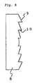
- Fig. 7 schematically showing the perspective view of the sheet.
- the Fresnel lens sheet 8 has a diffraction grating 9 formed on the surface of the Fresnel lens 10 of the sheet.
- Fig. 8 is a cross-sectional view of the Fresnel lens sheet of Fig. 7.
- the Fresnel lens sheet having the configuration illustrated may be produced in a 2P process utilizing a mold for a Fresnel lens sheet with a diffraction grating pattern on its surface to give the surface of the Fresnel lens.
- the Fresnel lens sheet having the configuration of that type does not require different steps of separately working the both surfaces of the Fresnel lens sheet in different ways, and its producibility is high.
- the rays of light having passed through a diffraction grating go out of it, at scattering angles to be determined by the number of diffraction orders.
- the diffracted rays are dispersed to lower the luminance from them.
- the diffracted rays of light are concentrated to a specific order, such as those of the primary order, the luminance relative to the outgoing angle of the diffracted rays of light that shall be determined by the diffraction order could be increased.
- the cross section of the diffraction grating may have a profile of saw teeth.
- the cross section of the diffraction grating may have different profiles of sine curves, triangles, rectangles, etc.
- Fresnel lens sheet of the invention may be combined with an ordinary lenticular lens sheet, for example, as in Fig. 10. If desired, a protective front sheet may be attached to the viewer s side of the lenticular lens sheet.
- the optical device of the invention has the advantage of little wavelength dependency of the angle of light passing through and going out of it, and is well applicable to Fresnel lenses with little coloration of light passing through it.
Landscapes
- Physics & Mathematics (AREA)
- General Physics & Mathematics (AREA)
- Optics & Photonics (AREA)
- Overhead Projectors And Projection Screens (AREA)
- Lenses (AREA)
- Diffracting Gratings Or Hologram Optical Elements (AREA)
Applications Claiming Priority (2)
| Application Number | Priority Date | Filing Date | Title |
|---|---|---|---|
| JP34279598 | 1998-12-02 | ||
| JP34279598 | 1998-12-02 |
Publications (2)
| Publication Number | Publication Date |
|---|---|
| EP1006400A2 true EP1006400A2 (de) | 2000-06-07 |
| EP1006400A3 EP1006400A3 (de) | 2003-05-14 |
Family
ID=18356565
Family Applications (1)
| Application Number | Title | Priority Date | Filing Date |
|---|---|---|---|
| EP99123273A Withdrawn EP1006400A3 (de) | 1998-12-02 | 1999-11-30 | Optische Vorrichtung und Fresnellinsen-Folie |
Country Status (4)
| Country | Link |
|---|---|
| US (1) | US6282034B1 (de) |
| EP (1) | EP1006400A3 (de) |
| KR (1) | KR100377970B1 (de) |
| CN (1) | CN1143142C (de) |
Cited By (5)
| Publication number | Priority date | Publication date | Assignee | Title |
|---|---|---|---|---|
| WO2003060575A1 (en) * | 2002-01-15 | 2003-07-24 | Reflexite Corporation | Grooved optical microstructure light collimating films |
| WO2003042760A3 (en) * | 2001-11-09 | 2003-10-02 | Xradia Inc | Lithography using achromatic fresnel optics |
| US6914723B2 (en) | 2001-11-09 | 2005-07-05 | Xradia, Inc. | Reflective lithography mask inspection tool based on achromatic Fresnel optics |
| US7119953B2 (en) * | 2002-12-27 | 2006-10-10 | Xradia, Inc. | Phase contrast microscope for short wavelength radiation and imaging method |
| WO2007115664A1 (de) * | 2006-04-06 | 2007-10-18 | Oc Oerlikon Balzers Ag | Projektionsbeleuchtungssystem, in dem linsen mit diffraktiv optischen elementen verwendet werden |
Families Citing this family (20)
| Publication number | Priority date | Publication date | Assignee | Title |
|---|---|---|---|---|
| JP2000171613A (ja) * | 1998-12-02 | 2000-06-23 | Kuraray Co Ltd | フレネルレンズシート |
| JP4395691B2 (ja) * | 2001-03-26 | 2010-01-13 | コニカミノルタビジネステクノロジーズ株式会社 | レーザー走査装置 |
| JP3868819B2 (ja) * | 2002-01-24 | 2007-01-17 | 大日本印刷株式会社 | フレネルレンズシート、透過型投影スクリーン、および透過型投影ディスプレイ |
| US6700708B2 (en) | 2002-05-30 | 2004-03-02 | Agere Systems, Inc. | Micro-lens array and method of making micro-lens array |
| US6896375B2 (en) * | 2002-08-16 | 2005-05-24 | Infocus Corporation | Rear projection display device having multiple mirrors that are substantially parallel to a screen |
| US7095558B2 (en) * | 2003-09-01 | 2006-08-22 | Hitachi, Ltd. | Image display device, rear projection type screen used in image display device, Fresnel lens sheet, and method of making Fresnel lens sheet |
| TWI356969B (en) * | 2003-10-14 | 2012-01-21 | Toppan Printing Co Ltd | Fresnel lens sheet, translucent type screen, and r |
| KR101117363B1 (ko) * | 2004-07-23 | 2012-03-08 | 히다치 가세고교 가부시끼가이샤 | 회절형 집광필름 및 그것을 이용한 면광원장치 |
| KR101119193B1 (ko) | 2004-12-30 | 2012-03-22 | 삼성전자주식회사 | 광원 유닛 및 이를 갖는 액정 표시 장치 |
| US20070273983A1 (en) * | 2006-05-26 | 2007-11-29 | Hebert Raymond T | Devices, methods, and systems for image viewing |
| CN102037405A (zh) * | 2008-05-20 | 2011-04-27 | 松下电器产业株式会社 | 透射型屏幕以及扩散板 |
| US8861086B2 (en) | 2010-08-13 | 2014-10-14 | The Penn State Research Foundation | Compact spectrometer including a diffractive optical element with dual dispersion and focusing functionality |
| TWI547717B (zh) * | 2015-05-13 | 2016-09-01 | 華邦電子股份有限公司 | 頭戴式顯示裝置 |
| WO2017023057A1 (ko) * | 2015-08-04 | 2017-02-09 | 엘지이노텍(주) | 렌즈, 광학 장치 및 이를 포함하는 가상 현실 구현을 위한 헤드 장착 표시 장치 |
| WO2017024145A1 (en) | 2015-08-05 | 2017-02-09 | Canon U.S.A., Inc. | Forward and angle view endoscope |
| US10284825B2 (en) | 2015-09-08 | 2019-05-07 | Rambus Inc. | Systems with integrated refractive and diffractive optics |
| US11181731B1 (en) | 2017-01-02 | 2021-11-23 | Kopin Corporation | Wide field of view (WFOV) optical system and method |
| JP7169052B2 (ja) * | 2017-07-11 | 2022-11-10 | 株式会社ダイセル | フレネルレンズ、及びその製造方法 |
| FR3071072B1 (fr) * | 2017-09-12 | 2022-08-12 | Valeo Vision | Lentille de mise en forme de rayons lumineux pour un module lumineux d’eclairage et/ou de signalisation d’un vehicule automobile |
| WO2020056484A1 (en) * | 2018-09-17 | 2020-03-26 | Hyperstealth Biotechnology Corporation | System and methods for laser scattering, deviation and manipulation |
Family Cites Families (6)
| Publication number | Priority date | Publication date | Assignee | Title |
|---|---|---|---|---|
| US2818765A (en) * | 1956-10-08 | 1958-01-07 | Bausch & Lomb | Method and means for achromatizing prisms |
| US5161057A (en) * | 1988-09-12 | 1992-11-03 | Johnson Kenneth C | Dispersion-compensated fresnel lens |
| DE4323971C2 (de) * | 1992-07-16 | 2002-11-07 | Asahi Optical Co Ltd | Schreib-/Lesegerät für eine optische Speicherplatte |
| KR0168879B1 (ko) * | 1992-12-25 | 1999-04-15 | 기따지마 요시또시 | 렌티큘러 렌즈, 면광원 및 액정 표시 장치 |
| US5619373A (en) * | 1995-06-07 | 1997-04-08 | Hasbro, Inc. | Optical system for a head mounted display |
| US6013664A (en) * | 1996-11-27 | 2000-01-11 | Bayer Aktiengesellschaft | Microbicidal agents based on thiophene-2-carboxylic acid derivatives |
-
1999
- 1999-11-26 KR KR10-1999-0053003A patent/KR100377970B1/ko not_active Expired - Fee Related
- 1999-11-30 EP EP99123273A patent/EP1006400A3/de not_active Withdrawn
- 1999-12-01 US US09/451,776 patent/US6282034B1/en not_active Expired - Fee Related
- 1999-12-02 CN CNB991159780A patent/CN1143142C/zh not_active Expired - Fee Related
Cited By (9)
| Publication number | Priority date | Publication date | Assignee | Title |
|---|---|---|---|---|
| WO2003042760A3 (en) * | 2001-11-09 | 2003-10-02 | Xradia Inc | Lithography using achromatic fresnel optics |
| US6885503B2 (en) | 2001-11-09 | 2005-04-26 | Xradia, Inc. | Achromatic fresnel optics based lithography for short wavelength electromagnetic radiations |
| US6914723B2 (en) | 2001-11-09 | 2005-07-05 | Xradia, Inc. | Reflective lithography mask inspection tool based on achromatic Fresnel optics |
| US6917472B1 (en) | 2001-11-09 | 2005-07-12 | Xradia, Inc. | Achromatic fresnel optics for ultraviolet and x-ray radiation |
| WO2003060575A1 (en) * | 2002-01-15 | 2003-07-24 | Reflexite Corporation | Grooved optical microstructure light collimating films |
| US6880946B2 (en) | 2002-01-15 | 2005-04-19 | Reflexite Corporation | Grooved optical microstructure light collimating films |
| US7119953B2 (en) * | 2002-12-27 | 2006-10-10 | Xradia, Inc. | Phase contrast microscope for short wavelength radiation and imaging method |
| US7414787B2 (en) | 2002-12-27 | 2008-08-19 | Xradia, Inc. | Phase contrast microscope for short wavelength radiation and imaging method |
| WO2007115664A1 (de) * | 2006-04-06 | 2007-10-18 | Oc Oerlikon Balzers Ag | Projektionsbeleuchtungssystem, in dem linsen mit diffraktiv optischen elementen verwendet werden |
Also Published As
| Publication number | Publication date |
|---|---|
| KR20000047738A (ko) | 2000-07-25 |
| EP1006400A3 (de) | 2003-05-14 |
| CN1143142C (zh) | 2004-03-24 |
| KR100377970B1 (ko) | 2003-03-29 |
| CN1261156A (zh) | 2000-07-26 |
| US6282034B1 (en) | 2001-08-28 |
Similar Documents
| Publication | Publication Date | Title |
|---|---|---|
| US6282034B1 (en) | Optical device and Fresnel lens sheet | |
| KR100248248B1 (ko) | 광학용시트,및 그것을 사용한 투과형스크린 | |
| US6785048B2 (en) | Rear-projection screen and rear-projection image display | |
| US6407860B1 (en) | Fresnel lens sheet | |
| JP2950219B2 (ja) | 面光源装置、当該面光源装置を用いた画像表示装置及び当該面光源装置に用いるプリズムアレイ | |
| US6989929B2 (en) | Fresnel lens sheet and rear projection screen including the same | |
| US6995907B2 (en) | Diffusion sheet for use in transmission-type screen and transmission-type screen | |
| EP1517174B1 (de) | Projektionsschirm und projektionsanzeigeeinrichtung | |
| US9581818B2 (en) | Head-mounted display optical system and head-mounted display | |
| JP2001042112A (ja) | 回折光学素子及びそれを用いた光学系 | |
| US7710651B2 (en) | Contacting two-layer diffractive optical element | |
| JPH09288269A (ja) | 高効率、高色純度の軸上ホログラフカラーフィルタおよびフルカラー液晶表示装置 | |
| US7102820B2 (en) | Flat valley fresnel lens for a display device | |
| US7317565B2 (en) | Projection viewing system | |
| JPH10301110A (ja) | 画像表示装置 | |
| JP3652260B2 (ja) | 回折光学素子、該回折光学素子を有する光学系、撮影装置、観察装置 | |
| US20120075704A1 (en) | Diffraction optical element | |
| US6930833B2 (en) | Diffractive optical element, and optical system and optical apparatus provide with the same | |
| JP7352862B2 (ja) | 光学部材及び表示装置 | |
| US6621640B2 (en) | Projection display apparatus | |
| US4118114A (en) | Low-glare overhead projector | |
| EP1039337A1 (de) | Rückprojektionsschirm | |
| JP2010096999A (ja) | 回折光学素子、回折光学部材及び光学系 | |
| JP3990536B2 (ja) | 光学補正をしたホログラフィック・スクリーン・プロジェクション・テレビジョン | |
| US6831783B2 (en) | Diffractive optical element and optical system |
Legal Events
| Date | Code | Title | Description |
|---|---|---|---|
| PUAI | Public reference made under article 153(3) epc to a published international application that has entered the european phase |
Free format text: ORIGINAL CODE: 0009012 |
|
| AK | Designated contracting states |
Kind code of ref document: A2 Designated state(s): AT BE CH CY DE DK ES FI FR GB GR IE IT LI LU MC NL PT SE |
|
| AX | Request for extension of the european patent |
Free format text: AL;LT;LV;MK;RO;SI |
|
| PUAL | Search report despatched |
Free format text: ORIGINAL CODE: 0009013 |
|
| RIC1 | Information provided on ipc code assigned before grant |
Ipc: 7H 04N 9/31 B Ipc: 7G 02B 5/18 B Ipc: 7G 02B 3/08 B Ipc: 7G 03B 21/62 A |
|
| AK | Designated contracting states |
Designated state(s): AT BE CH CY DE DK ES FI FR GB GR IE IT LI LU MC NL PT SE |
|
| AX | Request for extension of the european patent |
Extension state: AL LT LV MK RO SI |
|
| 17P | Request for examination filed |
Effective date: 20031028 |
|
| AKX | Designation fees paid |
Designated state(s): DE FR GB NL |
|
| 17Q | First examination report despatched |
Effective date: 20040114 |
|
| STAA | Information on the status of an ep patent application or granted ep patent |
Free format text: STATUS: THE APPLICATION IS DEEMED TO BE WITHDRAWN |
|
| 18D | Application deemed to be withdrawn |
Effective date: 20050106 |