WO2009141981A1 - 透過型スクリーンおよび拡散板 - Google Patents
透過型スクリーンおよび拡散板 Download PDFInfo
- Publication number
- WO2009141981A1 WO2009141981A1 PCT/JP2009/002130 JP2009002130W WO2009141981A1 WO 2009141981 A1 WO2009141981 A1 WO 2009141981A1 JP 2009002130 W JP2009002130 W JP 2009002130W WO 2009141981 A1 WO2009141981 A1 WO 2009141981A1
- Authority
- WO
- WIPO (PCT)
- Prior art keywords
- layer
- protective panel
- front protective
- light
- temperature
- Prior art date
- Legal status (The legal status is an assumption and is not a legal conclusion. Google has not performed a legal analysis and makes no representation as to the accuracy of the status listed.)
- Ceased
Links
Images










Classifications
-
- G—PHYSICS
- G03—PHOTOGRAPHY; CINEMATOGRAPHY; ANALOGOUS TECHNIQUES USING WAVES OTHER THAN OPTICAL WAVES; ELECTROGRAPHY; HOLOGRAPHY
- G03B—APPARATUS OR ARRANGEMENTS FOR TAKING PHOTOGRAPHS OR FOR PROJECTING OR VIEWING THEM; APPARATUS OR ARRANGEMENTS EMPLOYING ANALOGOUS TECHNIQUES USING WAVES OTHER THAN OPTICAL WAVES; ACCESSORIES THEREFOR
- G03B21/00—Projectors or projection-type viewers; Accessories therefor
- G03B21/54—Accessories
- G03B21/56—Projection screens
- G03B21/60—Projection screens characterised by the nature of the surface
- G03B21/62—Translucent screens
-
- G—PHYSICS
- G02—OPTICS
- G02B—OPTICAL ELEMENTS, SYSTEMS OR APPARATUS
- G02B3/00—Simple or compound lenses
- G02B3/02—Simple or compound lenses with non-spherical faces
- G02B3/08—Simple or compound lenses with non-spherical faces with discontinuous faces, e.g. Fresnel lens
-
- G—PHYSICS
- G02—OPTICS
- G02B—OPTICAL ELEMENTS, SYSTEMS OR APPARATUS
- G02B5/00—Optical elements other than lenses
- G02B5/20—Filters
- G02B5/205—Neutral density filters
Definitions
- the present invention relates to a transmissive screen used for a rear projector, and more particularly to a heat-resistant configuration of the transmissive screen.
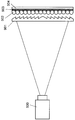
- FIG. 11 is a cross-sectional view showing a conceptual configuration of an example of a conventional transmission screen.
- the transmission screen according to the prior art is largely composed of a Fresnel lens sheet 901, a lenticular lens sheet 902, a light diffusion layer 903, and a transparent substrate 904.
- a projector 500 is installed behind the transmissive screen, and light from the projector 500 is projected onto the transmissive screen.
- FIG. 12 is a partial cross-sectional view showing a detailed configuration of a conventional transmission screen.
- the Fresnel lens sheet is omitted, and a specially configured lenticular lens sheet portion is enlarged.
- the light diffusing layer 903 is formed by applying a material made by dispersing light diffusing fine particles having a refractive index different from that of a binder material in a binder made of a transparent material to the transparent substrate 904 by means such as printing.
- the lenticular lens sheet 902 and the light diffusion layer 903 are joined by a transparent adhesive 913 with a light absorption layer (black stripe) 912 provided on a land portion 911 having a substantially trapezoidal cross-sectional shape on the emission side of the lenticular lens sheet 902. ing.
- the contrast to external light is improved by applying black stripes to the lenticular lens sheet.
- the black stripe portion absorbs light, and the temperature of the lenticular lens sheet rapidly increases.
- the temperature inside the housing of the rear projector also rises due to direct sunlight, the temperature increases as the components are further inside.
- Fresnel lens sheets and lenticular lens sheets have little room for selection in order to allow specific cross-sectional shapes to be formed with a precision higher than a predetermined level, making it difficult to use transparent and heat-resistant materials. is there.
- the influence on deformation due to temperature rise is large.
- the transmissive screen according to the related art has a problem in terms of heat resistance against direct sunlight.
- the observation surface of the transmission screen is exposed to the outside of the device. Therefore, unlike the case of installing indoors, the installation conditions such as temperature and humidity and lighting are diversified, and there is a possibility that an unspecified person may come into contact with the exposed part under various conditions. Ensuring quality with respect to vibration / impact strength, weather resistance, visibility of displayed images, and the like is an important issue. Specifically, comprehensive measures such as measures against temperature rise inside the housing due to direct sunlight, mechanical strength such as crack prevention against vibration and impact, etc., measures against reflection of images other than display images, etc. Countermeasures are required.
- the transmission screen according to the present invention includes, in order from the projection side, a Fresnel lens having a condensing function, a diffusion plate for diffusing incident light, and a front protection arranged with an air circulation layer at a predetermined interval with respect to the diffusion plate.
- a transmission type screen comprising a panel, wherein the front protective panel or the diffusion plate partially absorbs visible light.
- the visible light absorptivity of the front protective panel is the highest as compared with the Fresnel lens and the diffusion plate.
- the transmission screen of the present invention includes, in order from the projection side, a Fresnel lens having a condensing function, a diffusion plate that diffuses incident light, and a front surface that is disposed with an air circulation layer at a predetermined interval with respect to the diffusion plate.
- a transmission type screen comprising a protective panel, characterized in that a layer that absorbs or reflects infrared light is formed on the front protective panel, or a layer that absorbs or reflects ultraviolet light is formed on the front protective panel.
- the transmission screen does not need to be transparent to infrared rays and ultraviolet rays other than visible light, and by configuring in this way, the irradiation energy of direct sunlight can be reduced, so that the effect of suppressing the temperature rise is further improved.
- the transmission screen of the present invention includes, in order from the projection side, a Fresnel lens having a condensing function, a diffusion plate that diffuses incident light, and a front surface that is disposed with an air circulation layer at a predetermined interval with respect to the diffusion plate.
- a transmissive screen composed of a protective panel, the front protective panel comprising a protective substrate, a front protective layer disposed on the observer side of the protective substrate, and a rear surface disposed on the projection side of the protective substrate And a protective layer.
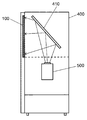
- FIG. 1A is a perspective view showing an overview of a rear projector equipped with a transmissive screen according to Embodiment 1 of the present invention.
- FIG. 1B is a diagram showing an internal configuration of a rear projector equipped with a transmissive screen according to Embodiment 1 of the present invention.
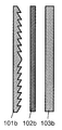
- FIG. 2 is a cross-sectional view showing a detailed configuration of the transmission screen according to Embodiment 1 of the present invention.
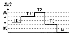
- FIG. 3A is a diagram showing a temperature rise graph of the transmission screen.
- FIG. 3B is a diagram showing a temperature rise graph of the transmission screen.
- FIG. 3C is a diagram showing a temperature rise graph of the transmission screen.
- FIG. 3D is a diagram showing a configuration of a transmission screen corresponding to FIG. 3A.
- FIG. 3E is a diagram showing a configuration of a transmission screen corresponding to FIG. 3B.
- FIG. 3F is a diagram showing a configuration of a transmission screen corresponding to FIG. 3C.
- FIG. 4 is a cross-sectional view showing a conceptual configuration of another example of the transmission screen according to Embodiment 1 of the present invention.
- FIG. 5 is a cross-sectional view showing a conceptual configuration of a transmission screen according to Embodiment 2 of the present invention.
- FIG. 6 is a diagram showing an example of optical characteristics related to the transmittance of the front protective panel according to Embodiment 2 of the present invention.
- FIG. 7A is a diagram showing a comparative experiment result of temperature increase using a lenticular lens sheet.
- FIG. 7B is a diagram showing a comparative experiment result of temperature increase using a lenticular lens sheet.
- FIG. 7C is a diagram showing a comparative experiment result of temperature increase using a lenticular lens sheet.
- FIG. 7D is a diagram showing a configuration of a transmissive screen corresponding to FIG. 7A.
- FIG. 7E is a diagram showing a configuration of a transmission screen corresponding to FIG. 7B.
- FIG. 7F is a diagram illustrating a configuration of a transmission screen corresponding to FIG. 7C.
- FIG. 8A is a diagram showing experimental results of temperature increase of the transmission screen of the present invention.
- FIG. 8B is a diagram showing an experimental result of temperature increase of the transmission screen of the present invention.
- FIG. 8C is a diagram showing an experimental result of temperature increase of the transmission screen of the present invention.
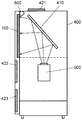
- FIG. 8D is a diagram showing a configuration of a transmission screen corresponding to FIG. 8A.
- FIG. 8E is a diagram showing a configuration of a transmission screen corresponding to FIG. 8B.
- FIG. 8F is a diagram showing a configuration of a transmission screen corresponding to FIG. 8C.
- FIG. 9A is a diagram for explaining a method of cooling the transmissive screen when the power supply to the rear projector is stopped due to a power failure or the like.
- FIG. 9B is a diagram for explaining a method of cooling the transmissive screen when power supply to the rear projector is stopped due to a power failure or the like.
- FIG. 9A is a diagram for explaining a method of cooling the transmissive screen when the power supply to the rear projector is stopped due to a power failure or the like.
- FIG. 9B is a diagram for explaining a method of cooling the transmissive
- FIG. 10A is a cross-sectional view showing a conceptual configuration of a front protective panel for a transmissive screen according to Embodiment 3 of the present invention.
- FIG. 10B is a cross-sectional view showing a conceptual configuration of the front protective panel of the transmission screen according to Embodiment 3 of the present invention.
- FIG. 10C is a cross-sectional view showing a conceptual configuration of the front protective panel of the transmission screen according to Embodiment 3 of the present invention.
- FIG. 10D is a cross-sectional view showing a conceptual configuration of the front protective panel of the transmissive screen according to Embodiment 3 of the present invention.
- FIG. 11 is a cross-sectional view showing a conceptual configuration of an example of a conventional transmission screen.
- FIG. 12 is a partial cross-sectional view showing a detailed configuration of a conventional transmission screen.
- FIG. 1 is a conceptual diagram showing a rear projector equipped with a transmissive screen according to Embodiment 1 of the present invention
- FIG. 1A is a perspective view showing an overview
- FIG. 1B is a diagram showing an internal configuration.
- Projector 500 is installed in housing 400.
- the transmission screen 100 is attached to the opening of the housing 400 so as to be visible from the outside.
- the reflecting plate 410 is installed inside.
- FIG. 2 is a cross-sectional view showing a detailed configuration of the transmission screen 100 of the present invention.
- the transmission screen 100 of the present invention includes a Fresnel lens 101, a diffusion plate 102, and a front protective panel 103 in order from the projector 500 side.
- the Fresnel lens 101 is formed concentrically so as to have a sawtooth cross section, and has a function of converging the diverging projection light on the viewer side.
- the diffusing plate 102 is a plate-like member that diffuses projection light by mixing fine particles having a refractive index different from that of one or more types of substrates into an acrylic resin or other transparent substrate as a scatterer. It is a thing. Or there is a sheet-like member.
- the front protective panel 103 is a plate-like member formed of a transparent base material.
- a material for the transparent substrate a material such as glass, acrylic resin, polycarbonate resin and the like that has not only transparency but also high physical strength and can be easily processed into a plate shape is suitable.
- the front protective panel 103 is colored by containing a tint material so as to partially absorb visible light.
- the diffusion plate 102 and the front protective panel 103 are held so as to maintain a predetermined distance, and the space forms a space (air circulation layer 104) in which air can flow.
- the predetermined distance may be any dimension that allows natural convection of air or forced cooling without bonding the front and rear members.
- the rear projector equipped with the transmissive screen 100 configured as described above may be installed not only indoors but also outdoors. When installed outdoors, it is necessary to protect the transmissive screen from physical damage.
- the transmissive screen 100 of the present invention has a plate-like front protective panel 103 having a high physical strength. Because it has, there is no problem in protecting the screen.
- transmissive screen 100 of the present invention configured as described above with respect to temperature rise.
- a transmissive screen is required to maintain contrast and heat resistance under direct sunlight.
- the colored tint layer absorbs light better than a transparent medium, and therefore the temperature tends to rise.
- the interior of the rear projector closed by the casing 400 becomes higher than the outside atmospheric temperature, and the temperature of the members arranged in the casing 400 is likely to rise.
- FIG. 3 is a diagram for explaining the difference in temperature rise due to the difference in the configuration of the transmissive screen.
- FIGS. 3A to 3C are diagrams showing temperature graphs of the transmissive screen, and FIGS. 3D to 3F correspond to FIGS. It is a figure which shows the structure of the transmissive screen to do.
- FIG. 3D is a configuration for comparing the effects of the transmission type screen of the present invention.
- the total light absorption rate is the same, but the configuration is based on the assumption that the diffuser plate 102 arranged at the center absorbs light most unlike the present invention. is there.
- Tb the internal temperature of the housing
- T1 the temperature of the Fresnel lens 101
- T2 the temperature of the diffusion plate 102
- T3 the temperature of the front protective panel 103
- Ta the atmospheric temperature outside the housing
- the housing temperature Tb is at least the energy of light reaching the inside and is higher than the atmospheric temperature Ta.
- the temperature T1 of the Fresnel lens is a temperature higher than Tb by absorbing part of the incident light.
- the temperature T3 of the front protective panel is higher than Ta by absorbing a part of incident light. In this configuration, it is assumed that the light absorption rate of the central diffusion plate 102 is the highest, so that the incident light is absorbed most and the temperature T2 of the diffusion plate is the highest.
- FIG. 3E shows the configuration of the transmission screen according to the present invention.
- the total absorption rate of light is the same as that of FIG. 3D, but the front protective panel 103 is configured to absorb the most light. is there.
- the internal temperature of the housing is Tb
- the temperature of the Fresnel lens 101 is T1
- the temperature of the diffusion plate 102 is T2
- the temperature of the front protection panel 103 is T3
- the enclosure temperature Tb is higher than the atmospheric temperature Ta as in the configuration of FIG. 3D.
- the temperature T1 of the Fresnel lens is also higher than Tb.
- the temperature T3 of the front protective panel is higher than that of the configuration of FIG. 3D with respect to Ta in order to absorb most of the incident light to the other members.
- the temperature T2 of the central diffusion plate is the same as that of the Fresnel lens 101, which is a member inside the housing, and it is estimated to be an intermediate temperature between T1 and T2 because it is located between them.
- the front protective panel 103 is formed as a tint layer so as to absorb a part of the visible light that is transmitted, thereby increasing the temperature of the diffusion plate and the Fresnel lens. It turns out that it can suppress.
- the front protective panel 103 is in a position where it comes into contact with the atmosphere outside the enclosure. It can be said that the temperature is higher than Ta and is advantageous for cooling.
- a tint sheet 301 which is a sheet colored with a dye or the like, to the base 302, the same effect can be obtained as a front protective panel.
- a tint may be provided on both the front protective panel 103 and the diffusion plate 102 so as to obtain an appropriate temperature distribution due to the relationship between the transmissive screen and the housing.
- the front protective panel 103 is set to have the highest visible light absorptivity compared to the Fresnel lens 101 and the diffuser plate 102, the effects of the present invention can be obtained in the same manner.
- FIG. 5 is a sectional view showing a conceptual configuration of a different embodiment of the transmission screen of the present invention.
- the same components as those in FIG. 2 are denoted by the same reference numerals, and description thereof is omitted.
- FIG. 5 is different from FIG. 2 in that an infrared reflection layer 201 is provided on the surface of the front protective panel 103.
- the transmissive screen does not need to be transparent to infrared rays and ultraviolet rays other than visible light, and by configuring in this way, the irradiation energy of direct sunlight can be reduced, so that the effect of suppressing the temperature rise is further improved.
- the irradiation energy of direct sunlight can be similarly reduced by providing a layer that absorbs infrared rays instead of the infrared reflecting layer 201.
- the irradiation energy of direct sunlight can be similarly reduced by providing a layer that reflects ultraviolet rays or a layer that absorbs ultraviolet rays.
- the irradiation energy of direct sunlight can be similarly reduced by providing a multilayered layer to provide a layer that reflects or absorbs both infrared rays and ultraviolet rays.
- FIG. 6 shows an example of optical characteristics regarding the transmittance of the front protective panel 103. As shown in FIG.
- the transmittance is almost 100% in the visible light region, but the transmittance is extremely lowered in the ultraviolet light region having a shorter wavelength and the infrared light region having a longer wavelength. Due to this characteristic, the entire protective panel 103 has a function of transmitting only visible light and reflecting or absorbing in the ultraviolet light region and the infrared light region.
- a coating having an antistatic function is applied to the surface of the front protective panel 103 exposed to the outside of the casing 400.
- a coat spray or an ion shower can be used.
- the front protective panel 103 can be prevented from being charged, and the surface of the transmissive screen 100 that is exposed to the outside of the casing 400 is not charged. Therefore, in the rear projector equipped with the transmissive screen 100 of the present invention, charged foreign matter does not adhere to the surface of the transmissive screen 100, and the surface of the transmissive screen 100 is maintained in a clean state free from dirt. Can do.
- FIG. 3F shows the configuration of the transmission screen according to the present embodiment, which is different from the configuration of FIG. 3E only in that an infrared reflection layer 201 is provided.
- the front protective panel 103 absorbs most light. It is configured.
- the temperature graph shown in FIG. 3C from the inside of the housing, the internal temperature of the housing is Tb, the temperature of the Fresnel lens 101 is T1, the temperature of the diffusion plate 102 is T2, the temperature of the front protective panel 103 is T3, and the atmospheric temperature outside the housing. Indicated by Ta.
- the amount of energy reflected by the infrared reflective layer 201 in the direct sunlight irradiated is lower than that in the configuration of FIG. 3E, and the other configurations are the same, so the internal temperature Tb, Fresnel
- the relative graph shapes of the lens temperature T1, the diffusion plate temperature T2, and the front protective panel temperature T3 increase with respect to the atmospheric temperature Ta are approximate to those in FIG. 3B, their absolute values are all low.
- the transmission screen has the configuration of the present embodiment, the effect of suppressing the temperature rise can be further increased.
- 3F shows an example in which the infrared reflective layer 201 is disposed on the front side of the front protective panel 103, the infrared reflective layer 201 may be disposed on the back side of the front protective panel 103.
- Example 1 An experiment was conducted to confirm the effect of suppressing the temperature rise of the transmission type screen of the present invention. The results of this experiment are shown in FIGS. 7A-C and FIGS. 8A-C. 7D to F show the configuration of the transmission screen corresponding to FIGS. 7A to C, and FIGS. 8D to 8F show the configuration of the transmission screen corresponding to FIGS. 8A to C.
- FIGS. 7D to 7F show configurations for comparing the degree of effect of the transmission screen of the present invention.
- the Fresnel lens 101 and the front protective panel 103 made of acrylic resin are the same as those of the present invention.
- a lenticular lens sheet 802 formed with black stripes corresponding to the above structure is used.
- 8D to 8F are the same as the transmission screen of the present invention, and are composed of a Fresnel lens 101, a diffusion plate 102, and a front protective panel 103 made of acrylic resin.
- the transmissive screen with the configuration shown in the figure is attached to the housing of the outdoor projector, and light of a predetermined energy as seen in direct sunlight is irradiated for a certain period of time.
- the temperature measurement location is the surface temperature of the lenticular lens sheet 802 in the configuration of FIGS. 7D to 7F, and the surface temperature of the diffusion plate 102 in the configuration of the present invention in FIG.
- the Fresnel lens 101 and the lenticular lens sheet 802 are bonded together, and the distance between the lenticular lens sheet 802 and the front protective panel 103 is set to 2 mm.
- the measurement temperature was 51 ° C. This was a temperature increase of 36 ° C. with respect to the outside air temperature of 15 ° C.
- the distance between the lenticular lens sheet 802 and the front protective panel 103 was set to 20 mm in the illustrated configuration. This corresponds to the air circulation layer 104 having a characteristic configuration of the present invention. Further, an infrared reflective layer 201 is provided on the surface of the front protective panel 103. And the energy density of the irradiated light measured temperature at 490 w / m ⁇ 2>, and the result became measurement temperature 40 degreeC. This was a temperature increase of 29 ° C. with respect to the outside air temperature of 11 ° C. The conversion temperature is 89 ° C.
- the Fresnel lens 101 and the diffuser plate 102 are bonded together to form the diffuser plate 102 and the front protective panel 103.
- the distance was set to 2 mm.
- the measurement temperature was 41 ° C. This was a temperature increase of 19.4 ° C. with respect to the outside air temperature of 21.6 ° C.
- the conversion temperature is 83 ° C.
- FIG. 8B shows the estimated temperature estimated from the experiment of FIG. 7B. 8E, as in FIG. 7E, if the distance between the diffuser plate 102 and the front protective panel 103 is set to 20 mm, and the infrared reflective layer 201 is installed on the surface of the front protective panel 103, FIG.
- the conversion temperature should be 10 ° C. lower than the conversion temperature.
- the conversion temperature of FIG. 7A and FIG. 7B is 99 degreeC and 89 degreeC, The difference can be estimated from 10 degreeC. Therefore, in the configuration of FIG. 8E, the converted temperature can be estimated as 73.degree.
- the air circulation layer 104 it is possible to create a forced air flow between the diffusion plate 102 and the front protective panel 103, thereby further suppressing the temperature rise. It can be seen from this experiment that the air circulation layer spacing is 2 mm or more, or 10 mm or more and 30 mm or less before and after 20 mm.
- the guaranteed temperature resistance of lenticular lenses is generally 60 ° C, and it can be seen that the conventional configuration cannot withstand outdoor use.
- a heat-resistant guaranteed temperature of 80 ° C. or higher is also readily available. It can be seen that a screen can be provided.
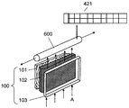
- FIGS. 9A and 9B are diagrams for explaining a method of cooling the transmission screen 100 when the power supply to the rear projector is stopped due to a power failure or the like.
- solar panels 421 and 422 and a battery 423 are disposed on the outer surface of the rear projector housing 400, for example, the top surface and the front panel (door).
- a cross fan 600 is provided above the transmission screen 100.
- the solar panels 421 and 422 have a function of performing solar power generation, and can be driven by supplying self-generated power to the cross fan 600 and other driving components. This makes it possible to cool the transmissive screen 100 even when the power supply of the rear projector is stopped due to a power failure, natural disaster, accident or intentional accident, and the temperature of the transmissive screen 100 increases. Can be protected.
- the battery 423 can be used in combination with a solar panel to store electric power supplied from the solar panels 421 and 422. Therefore, when the power supply to the rear projector is stopped for some reason, the power supply function from the solar panels 421 and 422 at night or when the power supply function is lowered or when a large amount of power is temporarily required is used. Demonstrate the effect.
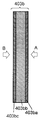
- the cross fan 600 is disposed on the inner side of the transmissive screen 100 (on the side facing the reflector 410), and the transmissive screen 100 rises in temperature due to outside air or direct light. Is generated and the transmissive screen 100 is cooled by operating when the temperature exceeds a certain temperature. Further, as shown in FIG. 9B, the cooling air A passes through the air circulation layer 104 (FIG. 5) of the transmission screen 100 and is exhausted in the axial direction of the cross fan 600, thereby efficiently cooling the transmission screen 100. It can be carried out.
- FIG. 3 are sectional views showing a conceptual configuration of the front protective panel 403 of the transmissive screen 200 according to the third embodiment of the present invention.
- the front protective panel 403 is related to the first embodiment of the present invention shown in FIG. Shows a different configuration.
- 10B, 10C, and 10D are partially enlarged views showing the detailed configuration of FIG. 10A. 10A to 10D, the same components as those in FIG. 2 are denoted by the same reference numerals, and description thereof is omitted.
- the front protective panel 403 disposed on the viewer side of the transmission screen 200 is exposed to the outside of the apparatus. Therefore, unlike the case where it is installed indoors, the front protective panel 403 has various installation conditions such as temperature and humidity, lighting, etc., and the possibility that an unspecified person may come into contact under various conditions. As for 403, it is important to ensure quality with respect to vibration / impact strength, weather resistance, display image visibility, and the like.
- mechanical measures such as measures against temperature rise inside the housing due to direct sunlight, crack prevention against vibration, impact, etc.
- Comprehensive practical measures are required, such as measures against high intensity and reflection of images other than the display image.
- the front protective panel 403a having the configuration shown in FIG. 10B will be described.
- the front protective panel 403a includes a protective base material 403ab, a front protective layer 403aa disposed on the observer side A (side facing the observer) of the protective base material 403ab, and a protective base material 403ab. And a rear surface protective layer 403ac disposed on the projection side B (opposite to the observer side).
- the protective substrate 403ab is a glass material having a function of protecting the transmission screen 200 and strength against external force
- the front protective layer 403aa is an antireflection layer having a function of preventing or suppressing light reflection.
- the back protective layer 403ac is a light shielding layer having a function of shielding light in some wavelength regions. Further, tempered glass is used as the protective substrate 403ab, a matte film is used for the front protective layer 403aa, and at least one of an ultraviolet cut film and an infrared cut film is used for the back protective layer 403ac.
- the front protective layer 403aa has a function of preventing reflection of an image other than a display image and a function of preventing scattering when the protective base material 403ab is cracked.
- tempered glass having a cracking strength 2 to 3 times that of general glass is used for the protective base material 403ab, and has a protection function against deformation and cracking of the transmission screen 200.
- tempered glass When using tempered glass for the protective substrate 403ab, it is necessary to consider the relationship between the strength of the glass and the smoothness of the surface. Since tempered glass applies compressive stress to the surface of the glass by a physical method or chemical method in the manufacturing process, the structure of the glass surface changes in this process, and the smoothness decreases. Therefore, as for the protective base material 403ab, when the strength of the tempered glass is increased, the smoothness of the surface is lowered, and an image other than the display image such as an object existing around the transmission screen 200 is reflected on the display surface. The display image quality is further deteriorated as compared with the case where the surface of the tempered glass is smooth. That is, since the surface of the tempered glass undulates, the reflected light does not become uniform on the glass surface, and the reflected image is distorted, resulting in an image that gives the viewer a sense of incongruity.
- the front protective layer 403aa using a mat film uses a material in which fine matte layers are formed by dispersing fine particles that scatter light on the surface of a light-transmitting substrate, or a material in which the surface is matted, and is transparently bonded. It can be configured by sticking to the protective base material 403ab with a material.
- the surface of the protective base material 403ab is smooth even though there are problems that the contrast is lowered due to the scattering of the reflected light and the resolution of the display image is lowered due to the scattering of the transmitted light. Since it is not easily affected by the degree, the strength of the tempered glass used for the protective base material 403ab can be increased as compared with the case of using an antireflection film or the like. Further, since the film is used, there is a feature that the effect of preventing scattering when the protective base material 403ab is cracked is also high.
- the front protective panel 403b having the configuration shown in FIG. 10C will be described.
- the front protective panel 403b has a three-layer structure including a protective substrate 403bb, a front protective layer 403ba, and a back protective layer 403bc.
- the protective substrate 403bb and the back protective layer 403bc are tempered glass and a light shielding layer, respectively, as in FIG. 10B.
- an antireflection film (hereinafter referred to as “AR dip”) formed by a dip method is used as the front protective layer 403ba in place of the mat film of FIG. 10B.
- AR dip an antireflection film
- the AR dip has better weather resistance than the antireflection film, and the rear projector can be used even outdoors exposed to direct sunlight.
- AR dip forms an antireflection film on the protective base material 403bb by attaching an antireflective solvent to the protective base material 403bb in a dip coating apparatus and performing heat treatment.
- This antireflection film acts as an optical interference layer, and attenuates the reflected light by causing interference of external light reflected by the front and back surfaces of the optical interference layer.
- the front protective layer 403aa (mat film) is used, and contrast, definition, reflection, etc. rather than strength are used.
- the front protective layer 403ba AR dip
- the front protective panel 403c having the configuration shown in FIG. 10D will be described.
- the front protective panel 403c includes a protective base material 403cb, a front protective layer 403ca, and a back protective layer 403cc.
- the protective substrate 403cb and the front protective layer 403ca are tempered glass and a mat film, respectively, as in FIG. 10B.
- the back protective layer 403cc has a two-layer structure.
- the rear protective layer 403cc is disposed for the purpose of preventing the temperature inside the rear projector housing 400 (FIG. 1) from rising due to direct sunlight or the like, and has a function of shielding light in a part of the wavelength region.
- As the light shielding layer provided at least one of an ultraviolet cut layer and an infrared cut layer is formed on the observer-side surface (observation surface: front surface) and the projection-side surface (projection surface: back surface) of the protective substrate 403cb.
- the ultraviolet cut layer has a function of shielding transmission of ultraviolet rays by absorbing or reflecting ultraviolet rays.
- the infrared cut layer has a function of shielding transmission of infrared rays by absorbing or reflecting infrared rays.
- the back protective layer 403cc has a two-layer structure, and the ultraviolet ray cut layer 403cc1 and the infrared ray cut layer 403cc2 (or the ultraviolet ray cut layer 403cc2 and the infrared ray cut layer 403cc1) are laminated in multiple layers, thereby relating to ultraviolet rays and infrared rays.
- the back surface protective layer 403cc having a shielding function is configured, and the temperature rise inside the casing 400 (FIG. 1) can be effectively suppressed.
- the ultraviolet cut layer 403cc1 and the infrared cut layer 403cc2 can be formed by vacuum deposition or sputtering, but an ultraviolet cut film or an infrared cut film may be attached to the protective substrate 403cb. Moreover, you may knead the component of an ultraviolet cut in the adhesive agent at the time of adhere
- the manufacturing cost of the front protection panel 403 the contrast of the display image, the blur of the display image, the temperature rise inside the housing 400, the reflection of unnecessary images on the display screen, the front protection
- the optimum structure of the front protective panel 403 may be determined by comprehensively considering various conditions such as the strength of the panel 403.
- the front protective panel 403 according to the third embodiment of the present invention when used, in the transmissive screen 200 of the outdoor rear projector, the mechanical resistance against the temperature rise, vibration, impact, etc. inside the housing due to direct sunlight etc. It is effective for practical problems such as high strength and scattering when broken, and reflection of an image other than the display image, and the effect can be surely exhibited. Therefore, it is possible to realize a high-quality outdoor transmission screen having excellent practicality.
- the transmission type screen and the diffusion plate according to the present invention satisfy not only the contrast of outside light but also the heat resistance against direct sunlight, and the outdoor use requires high quality in terms of weather resistance, strength and display image visibility. This is useful for rear projectors.
Landscapes
- Physics & Mathematics (AREA)
- General Physics & Mathematics (AREA)
- Optics & Photonics (AREA)
- Overhead Projectors And Projection Screens (AREA)
- Projection Apparatus (AREA)
- Optical Elements Other Than Lenses (AREA)
Abstract
Description
図1は、本発明の実施の形態1における透過型スクリーンを装着したリアプロジェクタを示す概念図であり、図1Aは概観を示す斜視図、図1Bは内部構成を示す図である。投写器500は筺体400内に設置される。また、透過型スクリーン100は、筺体400の開口部に外部より視認可能なように取り付けられる。一般に、投写器500から透過型スクリーン100までの光路長を確保し、かつ、筺体400内に部材を収めるために、反射板410が内部に設置されている。
図5は本発明の透過型スクリーンの異なる実施の形態の概念構成を示す断面図である。図2と同じ構成要素には同一の符号を付し説明を省略することとする。
本発明の透過型スクリーンの温度上昇を抑制する効果を確認する実験を行った。本実験の結果を図7A~Cと図8A~Cに示す。図7D~Fは、図7A~Cに対応する透過スクリーンの構成を示し、図8D~Fは、図8A~Cに対応する透過スクリーンの構成を示す。
図10A~Dは、本発明の実施の形態3における透過型スクリーン200の前面保護パネル403の概念構成を示す断面図であり、前面保護パネル403に関し、図2に示す本発明の実施の形態1と異なる構成を示す。図10B、図10C、図10Dは、図10Aの詳細な構成を示す一部拡大図である。なお、図10A~Dにおいて、図2と同じ構成要素には同一の符号を付し、説明を省略する。
101 フレネルレンズ
102 拡散板
103,403,403a,403b,403c 前面保護パネル
104 空気流通層
201 赤外線反射層
301 ティントシート
302 透明の基台
400 筺体
403aa,403ba,403ca 前面保護層
403ab,403bb,403cb 保護基材
403ac,403bc,403cc 背面保護層
403cc1 紫外線カット層
403cc2 赤外線カット層
410 反射板
421,422 ソーラーパネル
423 バッテリー
500 投写器
600 ファン
802,902 レンチキュラレンズシート
901 フレネルレンズシート
903 光拡散層
904 透明基材
911 ランド部
912 光吸収層
913 透明接着剤
A 観察者側
B 投写側
Claims (14)
- 投写側から順に、集光作用を有するフレネルレンズと、入射光を拡散する拡散板と、前記拡散板に対して所定間隔の空気流通層を隔てて配置された前面保護パネルで構成された透過型スクリーンであって、
前記前面保護パネルが可視光を部分的に吸収することを特徴とする透過型スクリーン。 - さらに前記拡散板が可視光を部分的に吸収することを特徴とする請求項1に記載の透過型スクリーン。
- 前記前面保護パネルの可視光吸収率が前記フレネルレンズ及び前記拡散板と比較して最も高いことを特徴とする請求項1または請求項2に記載の透過型スクリーン。
- 投写側から順に、集光作用を有するフレネルレンズと、入射光を拡散する拡散板と、前記拡散板に対して所定間隔の空気流通層を隔てて配置された前面保護パネルで構成された透過型スクリーンであって、
前記前面保護パネルに赤外線を吸収あるいは反射する層を形成したことを特徴とする透過型スクリーン。 - 投写側から順に、集光作用を有するフレネルレンズと、入射光を拡散する拡散板と、前記拡散板に対して所定間隔の空気流通層を隔てて配置された前面保護パネルで構成された透過型スクリーンであって、
前記前面保護パネルに紫外線を吸収あるいは反射する層を形成したことを特徴とする透過型スクリーン。 - 前記前面保護パネルの耐熱温度が少なくとも前記拡散板の耐熱温度と比較して高いことを特徴とする請求項1~5のいずれか1項に記載の透過型スクリーン。
- 前記前面保護パネルが、ガラス、アクリル樹脂、ポリカーボネイト樹脂のいずれか1つの材料で形成されることを特徴とする請求項6に記載の透過型スクリーン。
- 投写側から順に、集光作用を有するフレネルレンズと、入射光を拡散する拡散板と、前記拡散板に対して所定間隔の空気流通層を隔てて配置された前面保護パネルで構成された透過型スクリーンであって、
前記前面保護パネルは、保護基材と、前記保護基材の観察者側に配設した前面保護層と、前記保護基材の投写側に配設した背面保護層とを備えることを特徴とする透過型スクリーン。 - 前記保護基材はガラス材料であり、前記前面保護層は光の反射を防止または抑制する機能を備えた反射防止層であり、前記背面保護層は一部の波長領域の光を遮蔽する機能を備えた光遮蔽層であることを特徴とする請求項8に記載の透過型スクリーン。
- 前記保護基材は強化ガラスであり、前記前面保護層はマットフィルムであり、前記背面保護層は紫外線カットフィルムおよび赤外線カットフィルムの少なくともいずれかにより構成されることを特徴とする請求項9に記載の透過型スクリーン。
- 前記保護基材は強化ガラスであり、前記前面保護層はディップ法により形成された反射防止膜、前記背面保護層は紫外線カットフィルムおよび赤外線カットフィルムの少なくともいずれかにより構成されることを特徴とする請求項9に記載の透過型スクリーン。
- 前記背面保護層は紫外線カットフィルム層および赤外線カットフィルム層の2層から構成されることを特徴とする請求項10または請求項11に記載の透過型スクリーン。
- 前記保護パネルの表面に帯電防止処理が施されたことを特徴とする請求項1~12のいずれか1項に記載の透過型スクリーン。
- 請求項1~13のいずれか1項に記載の透過型スクリーンに使用される拡散板。
Priority Applications (3)
| Application Number | Priority Date | Filing Date | Title |
|---|---|---|---|
| CN2009801179213A CN102037405A (zh) | 2008-05-20 | 2009-05-15 | 透射型屏幕以及扩散板 |
| US12/935,009 US8072682B2 (en) | 2008-05-20 | 2009-05-15 | Transmissive screen and diffusion plate |
| JP2010512930A JPWO2009141981A1 (ja) | 2008-05-20 | 2009-05-15 | 透過型スクリーンおよび拡散板 |
Applications Claiming Priority (4)
| Application Number | Priority Date | Filing Date | Title |
|---|---|---|---|
| JP2008-131519 | 2008-05-20 | ||
| JP2008131519 | 2008-05-20 | ||
| JP2008265045 | 2008-10-14 | ||
| JP2008-265045 | 2008-10-14 |
Publications (1)
| Publication Number | Publication Date |
|---|---|
| WO2009141981A1 true WO2009141981A1 (ja) | 2009-11-26 |
Family
ID=41339921
Family Applications (1)
| Application Number | Title | Priority Date | Filing Date |
|---|---|---|---|
| PCT/JP2009/002130 Ceased WO2009141981A1 (ja) | 2008-05-20 | 2009-05-15 | 透過型スクリーンおよび拡散板 |
Country Status (4)
| Country | Link |
|---|---|
| US (1) | US8072682B2 (ja) |
| JP (1) | JPWO2009141981A1 (ja) |
| CN (1) | CN102037405A (ja) |
| WO (1) | WO2009141981A1 (ja) |
Cited By (4)
| Publication number | Priority date | Publication date | Assignee | Title |
|---|---|---|---|---|
| JP2015232630A (ja) * | 2014-06-10 | 2015-12-24 | 平岡織染株式会社 | 透過投映スクリーン |
| JP2015232629A (ja) * | 2014-06-10 | 2015-12-24 | 平岡織染株式会社 | 透過投映スクリーン |
| JP2016009150A (ja) * | 2014-06-26 | 2016-01-18 | 平岡織染株式会社 | 透過投映スクリーン |
| JP2016009149A (ja) * | 2014-06-26 | 2016-01-18 | 平岡織染株式会社 | 透過投映スクリーン |
Families Citing this family (5)
| Publication number | Priority date | Publication date | Assignee | Title |
|---|---|---|---|---|
| CN102109751B (zh) * | 2009-12-29 | 2013-08-07 | 财团法人工业技术研究院 | 微型成像模块、应用之立体显示系统及影像排列方法 |
| DE102011118181A1 (de) | 2011-11-10 | 2013-05-16 | GM Global Technology Operations LLC (n. d. Gesetzen des Staates Delaware) | Querträger einer Kraftfahrzeugkarosserie |
| US9690183B2 (en) * | 2014-10-07 | 2017-06-27 | Casio Computer Co., Ltd. | Display apparatus including image projecting unit and screen unit |
| JP6401122B2 (ja) * | 2015-07-30 | 2018-10-03 | 矢崎総業株式会社 | 二次電池状態検出装置 |
| US10095097B2 (en) * | 2016-11-29 | 2018-10-09 | Hyundai Motor Company | Projection-type optical module |
Citations (6)
| Publication number | Priority date | Publication date | Assignee | Title |
|---|---|---|---|---|
| JPH08237583A (ja) * | 1994-12-28 | 1996-09-13 | Hitachi Ltd | 透過型スクリーン及び背面投写型画像ディスプレイ装置並びにマルチスクリーンディスプレイ装置 |
| JP2001238226A (ja) * | 2000-02-21 | 2001-08-31 | Kuraray Co Ltd | 透過型スクリーン用前面パネル |
| JP2001296606A (ja) * | 2000-02-10 | 2001-10-26 | Sony Corp | 前面板取付装置、プロジェクタ装置及びプロジェクタ装置の製造方法 |
| JP2005018070A (ja) * | 2003-06-24 | 2005-01-20 | Samsung Electronics Co Ltd | 垂直及び水平に光視野角を有する映像表示用のスクリーン及びこれを備えるプロジェクションテレビ |
| JP2005049614A (ja) * | 2003-07-29 | 2005-02-24 | Toppan Printing Co Ltd | 透過型スクリーン用前面板 |
| JP2005114926A (ja) * | 2003-10-06 | 2005-04-28 | Kuraray Co Ltd | レンズシートの切断方法 |
Family Cites Families (9)
| Publication number | Priority date | Publication date | Assignee | Title |
|---|---|---|---|---|
| JP3646454B2 (ja) | 1997-03-06 | 2005-05-11 | 凸版印刷株式会社 | 画像投影用スクリーン |
| KR100377970B1 (ko) * | 1998-12-02 | 2003-03-29 | 가부시키가이샤 구라레 | 광학소자 및 프레넬 렌즈 시트 |
| US6327091B1 (en) * | 1999-01-18 | 2001-12-04 | Fuji Photo Film Co., Ltd. | Collimating plate and backlight system |
| DE60137614D1 (de) * | 2000-07-17 | 2009-03-26 | Sony Corp | Projektionstafelanordnung, Projektionsgerät, und Verfahren zur Herstellung |
| JP2003287819A (ja) | 2002-03-28 | 2003-10-10 | Matsushita Electric Ind Co Ltd | 背面投射型スクリーンおよび背面投射型ディスプレイ |
| JP2004045588A (ja) | 2002-07-10 | 2004-02-12 | Toppan Printing Co Ltd | 透過型スクリーン |
| JP2004093848A (ja) * | 2002-08-30 | 2004-03-25 | Toppan Printing Co Ltd | 光拡散性スクリーンおよびこのスクリーンを用いた表示装置 |
| US7262911B2 (en) * | 2004-03-15 | 2007-08-28 | Arisawa Mfg. Co., Ltd. | Reflex-type screen assembly |
| TWI386315B (zh) * | 2004-12-20 | 2013-02-21 | Mitsubishi Gas Chemical Co | 塑膠片 |
-
2009
- 2009-05-15 WO PCT/JP2009/002130 patent/WO2009141981A1/ja not_active Ceased
- 2009-05-15 CN CN2009801179213A patent/CN102037405A/zh active Pending
- 2009-05-15 US US12/935,009 patent/US8072682B2/en not_active Expired - Fee Related
- 2009-05-15 JP JP2010512930A patent/JPWO2009141981A1/ja active Pending
Patent Citations (6)
| Publication number | Priority date | Publication date | Assignee | Title |
|---|---|---|---|---|
| JPH08237583A (ja) * | 1994-12-28 | 1996-09-13 | Hitachi Ltd | 透過型スクリーン及び背面投写型画像ディスプレイ装置並びにマルチスクリーンディスプレイ装置 |
| JP2001296606A (ja) * | 2000-02-10 | 2001-10-26 | Sony Corp | 前面板取付装置、プロジェクタ装置及びプロジェクタ装置の製造方法 |
| JP2001238226A (ja) * | 2000-02-21 | 2001-08-31 | Kuraray Co Ltd | 透過型スクリーン用前面パネル |
| JP2005018070A (ja) * | 2003-06-24 | 2005-01-20 | Samsung Electronics Co Ltd | 垂直及び水平に光視野角を有する映像表示用のスクリーン及びこれを備えるプロジェクションテレビ |
| JP2005049614A (ja) * | 2003-07-29 | 2005-02-24 | Toppan Printing Co Ltd | 透過型スクリーン用前面板 |
| JP2005114926A (ja) * | 2003-10-06 | 2005-04-28 | Kuraray Co Ltd | レンズシートの切断方法 |
Cited By (4)
| Publication number | Priority date | Publication date | Assignee | Title |
|---|---|---|---|---|
| JP2015232630A (ja) * | 2014-06-10 | 2015-12-24 | 平岡織染株式会社 | 透過投映スクリーン |
| JP2015232629A (ja) * | 2014-06-10 | 2015-12-24 | 平岡織染株式会社 | 透過投映スクリーン |
| JP2016009150A (ja) * | 2014-06-26 | 2016-01-18 | 平岡織染株式会社 | 透過投映スクリーン |
| JP2016009149A (ja) * | 2014-06-26 | 2016-01-18 | 平岡織染株式会社 | 透過投映スクリーン |
Also Published As
| Publication number | Publication date |
|---|---|
| US20110019270A1 (en) | 2011-01-27 |
| JPWO2009141981A1 (ja) | 2011-09-29 |
| CN102037405A (zh) | 2011-04-27 |
| US8072682B2 (en) | 2011-12-06 |
Similar Documents
| Publication | Publication Date | Title |
|---|---|---|
| JPWO2009141981A1 (ja) | 透過型スクリーンおよび拡散板 | |
| TWI258111B (en) | Display panel device | |
| US7502169B2 (en) | Contrast enhancement films for direct-view displays and fabrication methods therefor | |
| US8130446B2 (en) | Optical diffusing sheet, optical deflecting sheet, and transmission type screen | |
| JP4976587B2 (ja) | 表示装置 | |
| US8508703B2 (en) | Display device | |
| JP5830831B2 (ja) | 液晶表示装置 | |
| JP2004062084A (ja) | 視認性向上シートおよびこれを用いたディスプレイ | |
| JP2010008895A (ja) | 光学部材および表示装置 | |
| KR101065725B1 (ko) | 프로젝션 및/또는 백프로젝션 스크린 | |
| US12235531B2 (en) | Glass backplane and method of manufacturing the same, and display apparatus | |
| JP2016009149A (ja) | 透過投映スクリーン | |
| WO2007062055A1 (en) | High contrast projection system with a reflective louver structure | |
| JP6638503B2 (ja) | 反射スクリーン、映像表示システム | |
| JP7285735B2 (ja) | 映像表示システムおよび映像表示方法 | |
| JP2012073363A (ja) | 反射スクリーン、反射スクリーン装置、映像表示システム | |
| JP2016151649A (ja) | 反射スクリーン、映像表示システム | |
| JP6287007B2 (ja) | 反射スクリーンおよび反射スクリーンを備えた映像表示システム | |
| JP2015075724A (ja) | 反射層の形成方法、反射型スクリーンの製造方法 | |
| JP4673681B2 (ja) | 積層体 | |
| JP5611513B2 (ja) | 光学部材および表示装置 | |
| JP5407109B2 (ja) | 透過型スクリーン | |
| JP2004045588A (ja) | 透過型スクリーン | |
| JP2007316415A (ja) | シート状部材、透過型スクリーンおよび背面投射型映像表示装置 | |
| JP2004184483A (ja) | ディスプレイ装置 |
Legal Events
| Date | Code | Title | Description |
|---|---|---|---|
| WWE | Wipo information: entry into national phase |
Ref document number: 200980117921.3 Country of ref document: CN |
|
| 121 | Ep: the epo has been informed by wipo that ep was designated in this application |
Ref document number: 09750343 Country of ref document: EP Kind code of ref document: A1 |
|
| WWE | Wipo information: entry into national phase |
Ref document number: 2010512930 Country of ref document: JP |
|
| WWE | Wipo information: entry into national phase |
Ref document number: 12935009 Country of ref document: US |
|
| NENP | Non-entry into the national phase |
Ref country code: DE |
|
| 122 | Ep: pct application non-entry in european phase |
Ref document number: 09750343 Country of ref document: EP Kind code of ref document: A1 |