EP1006497A1 - Dispositif de distribution d'articles pour distributeur automatique - Google Patents
Dispositif de distribution d'articles pour distributeur automatique Download PDFInfo
- Publication number
- EP1006497A1 EP1006497A1 EP98122716A EP98122716A EP1006497A1 EP 1006497 A1 EP1006497 A1 EP 1006497A1 EP 98122716 A EP98122716 A EP 98122716A EP 98122716 A EP98122716 A EP 98122716A EP 1006497 A1 EP1006497 A1 EP 1006497A1
- Authority
- EP
- European Patent Office
- Prior art keywords
- article
- holders
- passages
- driving shaft
- partition wall
- Prior art date
- Legal status (The legal status is an assumption and is not a legal conclusion. Google has not performed a legal analysis and makes no representation as to the accuracy of the status listed.)
- Withdrawn
Links
Images








Classifications
-
- G—PHYSICS
- G07—CHECKING-DEVICES
- G07F—COIN-FREED OR LIKE APPARATUS
- G07F11/00—Coin-freed apparatus for dispensing, or the like, discrete articles
- G07F11/02—Coin-freed apparatus for dispensing, or the like, discrete articles from non-movable magazines
- G07F11/38—Coin-freed apparatus for dispensing, or the like, discrete articles from non-movable magazines in which the magazines are horizontal
- G07F11/42—Coin-freed apparatus for dispensing, or the like, discrete articles from non-movable magazines in which the magazines are horizontal the articles being delivered by motor-driven means
Definitions
- the present invention relates to an article dispensing apparatus for an automatic vending machine of the type which contains a large number of articles arranged one after the other within an article passage such that one article is dispensed from the front side of the article passage when the article is purchased.
- an article dispensing apparatus 50 has an article rack 51 partitioned by a central partition wall 54 to form two article passages 52 on the right and left sides.
- a transparent open/close plate 55 is arranged for opening and closing dispensing ports of the article passages 52.
- pushers 56 are arranged such that a large number of articles S are contained in the respective article passages 52 one after the other, as sandwiched between the open /close plate 55 and the pushers 56.
- the open/close plate 55 is linked to the front end of a driving shaft 59 through a gear, which extends through the partition wall 54.
- the driving shaft 59 is driven by a driving mechanism (not shown) disposed behind the article rack 51 for rotation.
- a flapper 58 is arranged continuously with the front end of each of the article passages 52.
- the flapper 58 is linked to the driving shaft 59 through an interlock mechanism 60, so that it is supported in a horizontal posture during a purchase waiting state (see Fig. 4).
- the driving mechanism When the article S is purchased, the driving mechanism is actuated to rotate the driving shaft 59 in a predetermined direction over a predetermined angular distance, as illustrated in Fig. 5, causing the open/close plate 55 to pivotally move to open the article passage 52 of the opposite side.
- the flapper 58 of the opened article passage 52 is released from the supporting of the interlock mechanism 60, so that it is fee to pivotally move in a front downward direction. This causes the article (purchased article) S positioned at the forefront of the opened article passage 52 to be dispensed therefrom.
- the article dispensing apparatus 50 is also provided with two holders 57 for holding the second article (next sold article) from the front to prevent it from being dispensed when the first article is being purchased.
- Each of the holders 57 which may be formed of a bent plate (see Fig. 4), has a rear end portion pivotably supported by a supporting shaft 62 arranged perpendicular to a holder support 61 disposed in the partition wall 54.
- each of the holders 57 is arranged for advancement and retraction relative to a corresponding article passage 52 from an opening of the partition wall 54.
- the driving shaft 59 extends between the two holders 57 through notches formed through rear lower portions of the respective holders 57.
- the driving shaft 59 is integrally formed at this portion with a cam 63.
- the cam 63 is an eccentric cam which has a cam surface 63a only on one side with respect to the driving shaft 59 (on the upper side in Fig. 2). Also, each of the holders 57 is urged by associated springs, not shown, toward a retracting position.
- the holder 57 of the article passage 52 With the rotation of the driving shaft 59 responsive to a purchasing manipulation, the holder 57 of the article passage 52, from which an article is to be dispensed, is pressed by the cam surface 63a of the cam 63 so that it protrudes into the article passage 52. Thus, the holder 57 sandwiches the next sold article S with a side wall 52a opposite thereto, so that the next sold article S is supported thereby against a pressing force of the pusher 56. In this event, the other holder 57 is maintained in a retracted state within the partition wall 54 by an urging force of the spring.
- the article dispensing apparatus 50 mentioned above still has room for improvement in the following aspects.
- the article dispensing apparatus 50 when an article S is purchased, the article S is supported by only the protruding holder 57 associated with the article passage 52, from which the article S is to be dispensed, so that a pressing force of the pusher 56 acts as a large moment onto the supporting shaft 62 for supporting the holder 57 through the next sold article S.
- the holder support 61 for supporting the supporting shaft 62 must be extended downwardly beyond the driving shaft 59 such that the holder support 61 is supported by the partition wall 54 over a large supporting area thereof, in order to support this large moment.
- the present invention has been made to solve the problem as mentioned above, and its object is to provide an article dispensing apparatus for an automatic vending machine which is capable of appropriately supporting a holder for a next sold article in a simple, compact and inexpensive structure.
- an article dispensing apparatus for an automatic vending machine comprises an article rack having right and left article passages formed therein for containing a large number of articles arranged one after the other, wherein the article passages are partitioned from each other by a partition wall, and each of the article passages has a dispensing port at a front end thereof, article racks partitioned from each other by a partition wall, each of the article racks having a dispensing port at a front end thereof and having right and left article passages formed for containing a large number of articles arranged one after the other, a driving shaft extending within the partition wall in a longitudinal direction, an open/close member driven by the driving shaft to open the dispensing port of the article passage when an article is purchased, pushers for pressing articles contained in the article passages toward the front, a holder support having a supporting shaft extending in the vertical direction, and disposed in the partition wall, and right and left holders pivotably supported by the supporting shaft, each of the holders pivotally
- the open/close member closes the dispensing port of the article passage in a purchase waiting state, so that a large number of articles are contained one after the other in the article passage, as sandwiched between the open /close member and the pusher.
- the driving shaft is rotated to drive the open/close member to open the dispensing port of the article passage, thereby dispensing the article at the forefront (sold article) from the article rack.
- the right and left holders are driven by the cam to protrude into the right and left article passages (to a protruding position), respectively, to hold the second articles from the forefront (next sold articles) of the respective article passages.
- a smaller holder support may be utilized, and a structure for forcing the partition wall to support the pressing forces of the pushers is not necessary, thereby making it possible to make the holder support compact and simplify the partition wall.
- a bending moment acting on the driving shaft becomes very small, the driving shaft and other bearings need not be reinforced. With a reduction in size and a simplified structure as mentioned above, it is possible to reduce the cost.
- the holder support includes right and left stoppers each extending outside of the supporting shaft, where each of the stoppers is arranged to define a small gap between an associated one of the right and left holders and the stopper itself when it is positioned at the protruding position.
- the driving shaft is slightly deformed toward the sold-out article passage, so that the holder associated with that article passage comes in contact with the holder support and is stopped or supported thereby.
- a large moment will not act on the supporting shaft, and a sufficient protruding amount can be ensured for the other holder, thereby making it possible to hold the next sold article without hinderance.
- an automatic vending machine 2 is of a so-called see-through type which allows potential purchasers to externally view articles, actually sold thereby, such as canned beverages, packed beverages and so on.
- the automatic vending machine 2 comprises a vending machine body 3 which contains an article dispensing apparatus 1 according to the present invention, a main door 4 attached on the front of the vending machine body 3, and a transparent heat-insulating door 5 positioned between the vending machine body 3 and the main door 4.
- the vending machine body 3 is provided therein with a plurality of article racks 10 which form part of the article dispensing apparatus 1.
- a total of 24 article racks 10 are provided in a such configuration that they are arranged in eight vertical stages and three horizontal columns, wherein the same kind of articles S are contained in each of the article racks 10.
- the main door 4 is provided on the front surface thereof with a money insertion slot section 4a, a plurality of article selecting buttons 4b, an article pickup port 4c, and a front window 4d constituting an article display.
- the article selecting buttons 4b are equal in number to the article racks 10, and arranged in the same matrix arrangement as the article racks 10.
- a purchaser may select an article S upon purchase of an article by entering an appropriate amount of money through the money insertion slot section 4a, and pushing an article selecting button 4b corresponding to an article rack which contains the article S to be purchased.
- the vending machine body 3 is additionally provided with an elevator 6 in an internal space in front of the article rack 10. An article S dispensed from an article rack 10, when sold, is carried on a carrier plate 6a of the elevator 6, transported to the vicinity of a shutter 3a disposed on the bottom, and finally delivered to the article pickup port 4c through the shutter 3a.
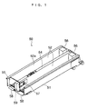
- each of the article racks 10 includes a rack body 11 and an adaptor 12 attached to the front end of the rack body 11.
- the rack body 11 is made of a bent sill plate and is formed therein with right and left article passages 14 partitioned by a central partition 13.
- Each of the article passages 14 is formed with a dispensing port 14a at the front end thereof.
- the adaptor 12 is formed of integral molding made of synthetic resin (for example, polypropylene) in a frame shape, fitted in the front end of the rack body 11, and fixed by screws.
- oblique guide surfaces 12b are formed on both sides of a central horizontal surface 12a.
- the oblique guide surfaces 12b are inclined in a lower front direction and continuous to the bottom of the article passage 14.
- Each of the oblique guide surface 12b is formed with a plurality of long grooves 12c extending in the longitudinal direction for relieving a frictional resistance of the article S.
- the front end of the oblique guide surface 12b protrudes in a jaw shape to serve as a handle 12d for the article rack 10.
- the horizontal surface 12a of the adaptor 12 is formed with mounting holes 12e for mounting right and left open/close plates 18, later described, respectively.
- the article rack 10 constructed as described above is longitudinally movably carried on a shelf 15 (Fig. 4) disposed in the vending machine body 3 through rollers 16 and so on.
- the article rack 10 is usually retracted in the vending machine body 3 as illustrated in Fig. 10 or the like, and is drawn to the front from the vending machine body 3 for supplementing articles S or for other occasions.
- the article dispensing apparatus 1 is further provided with a dispensing mechanism 17 for dispensing an article S when it is purchased.
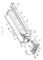
- the dispensing mechanism 17 comprises dispensing ports 14a at the front ends of the two article passages 14; right and left open/close plates (open/close members) for opening and closing the dispensing ports 14a; springs (not shown) for urging the open/close plates 18; a stopper plate 19 for stopping and releasing the two open/close plates 18; right and left holders 20 for holding the second article (next sold article) S from the forefront when the first article S is being purchased; a driving mechanism 21 for driving the stopper plate 19 and the holders 20; and so on.
- Each of the open/close plates 18 is made of transparent synthetic resin (for example, polycarbonate), and formed with a concentric notch 22 in a semi-arc shape in a lower inside thereof as well as a semi-arcuate protrusion 23 along the notch 22 on the front surface thereof. Also, pivots 18a are formed beyond upper and lower ends of the inner edge of each of the open/close plates 18 (see Fig. 12 or the like). The upper pivot 18a is fitted in a mounting hole (not shown) of the partition wall 13, while the lower pivot 18a is fitted in a mounting hole 12e of the adaptor 12 of the article rack 10.
- transparent synthetic resin for example, polycarbonate
- the open/close plate 18 is pivotably supported in a central portion of the article rack 10 about the vertical axis so that it is pivotably movable between a closed position for closing the dispensing port 14a of the article passage 14 and an open position for opening the same. Also, each of the open/close plates 18 is constantly urged by the aforementioned spring toward the open position (in the direction indicated by the arrow B in Fig. 12).
- the stopper plate 19 which in turn is formed of a circular plate made of opaque synthetic resin (for example, polyacetal), has the lower end fixed to the distal end of the driving shaft 24.
- the driving shaft 24 is disposed at a concentric position with the semi-arcuate protrusion 23 of the open/close plate 18, and extends through the partition wall 13 and the notch 22 of the open/close plate 18 in the longitudinal direction (see Fig. 12).
- the driving shaft 24, which forms part of the driving mechanism 21 has its rear end linked to a decelerating gear 25 of the driving mechanism 21, so that it is driven by an actuated motor 26 for rotation upon selling an article.
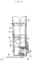
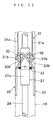
- Each of the holders 20, which may be a bent plate as illustrated in Figs. 12 and 13, has its rear end pivotably supported by a supporting shaft 32 arranged perpendicular to a holder support 31 disposed in the partition wall 13, and is pivotally movable between a protruding position at which it protrudes into the article passage 14 from an opening of the partition wall 13 (the position illustrated in Fig. 14 and 15) and a retracting position at which it is retracted from the article passage 14 (the position illustrated in Figs. 12 and 13).
- the two holders 20 are urged by coil springs 33 in a mutually approaching direction, i.e., toward the retracting position.
- a notch 20a is formed behind a lower portion of each of the holders 20, and a rear end portion of the holder 20, facing the notch 20a, serves as a cam abutting portion 20b which is curved outwardly.
- the driving shaft 24 extends between the two holders 20 through the notch 20a, and a cam 27 is integrally formed in this portion of the driving shaft 24.
- the cam 27 has two symmetric cam surfaces 27a about the driving shaft 24, and abuts to the cam abutting portion 20b of the holder 20, as illustrated in Fig. 14 and so on.
- the cam 27 has the cam surfaces 27a in the upper and lower directions during a purchase waiting state, and the two holders 20 are held at the retracting position by a spring force of the coil spring 33.
- the driving shaft 24 is rotated over an angular distance of 90° to cause the cam surfaces 27a to press the two holders 20, respectively, which are pivotally moved to the protruding position at the same time.
- the holder support 31 for supporting the holder 20 is formed in a box shape by combining two steel plates, each of which is C-shaped in cross-section.
- the holder support 31 is formed with a stopper 31b.
- the stopper 31b extends slightly outwardly and outside the supporting shaft 32.
- the stopper 31b is arranged such that a small gap G is defined between the tip of the stopper 31b and the holder 20 when the holder 20 is moved to the protruding position.
- the holder support 31 is longitudinally movably attached to the partition wall 13, so that the holder support 31 can be moved for adjustment in the longitudinal direction by moving the holder support 31 and the holder 20 while manipulating a lever 28 urged upwardly by a spring (not shown), and then stopping the lever 28 at a stopper groove 34 (see Fig. 10). In this way, the next sold article S can be held by the holder 20 corresponding to a change in size of the article S.
- the article dispensing apparatus 1 further includes two right and left pushers 29 for pressing articles S in the respective article passages 14 toward the front; and guide rails 30 for guiding the pushers 29.
- Each of the pushers 29 is constructed of a block-like pusher body 29a; a pair of front and rear rollers 29b attached to an upper portion of a side surface of the pusher body 29a and formed with a U-shaped groove (a front-side one only is illustrated); and an auxiliary roller 29c below the front and rear rollers 29b.
- the pusher 29 is constantly urged by an extension spring (not shown) toward the front.
- the guide rail 30 in turn is formed, for example, of aluminum extrusion molding, and is attached to a central portion of a shelf 15, which carries the upper article rack 10, so as to protrude downwardly and extend in the longitudinal direction.
- the pusher 29 is smoothly guided in the longitudinal direction along the guide rail 30 by the rollers 29b engaging with guide protrusions 30a on both sides of the guide rail 30.
- a purchase waiting state illustrated in Fig. 12 the stopper plate 19 is held in a stop position by the driving mechanism 21, and abuts to the right and left open/close plates 18 from the front side to stop the right and left open/close plates 18 at their closed positions.
- a large number of articles S are contained in the respective article passages 14 arranged one after the other, and sandwiched between the closed open/close plates 18 and the pushers 29.
- the cam 27 remains at an angle at which the cam surfaces 27a are positioned at the top and bottom.
- the two holders 20 are held at the retracting position by a spring force of the coil spring 33 (see Fig. 13).
- the driving shaft 24 is rotated over an angular distance of 90° in the direction indicated by the arrow C in Fig. 14 by the actuation of the motor 26 of the driving mechanism 21 for dispensing the article S from the left-hand article passage 14.
- the stopper plate 19 is pivotally moved over the same angular distance toward the right-hand open/close plate 18 to the releasing position, causing the left-hand open/close plate 18 to come off the stopper plate 19 to release the left-hand open/close plate 18.
- the left-hand open/close plate 18 is pivotally moved to the open position by an urging force of a spring, not shown, to open the dispensing port 14a of the left-hand article passage 14, thereby dispensing the article (purchased article) S at the forefront from the article passage 14.
- the rotation of the driving shaft 24 causes the cam surfaces 27a of the cam 27 to press the holders 20 through the respective cam abutting portions 20b, so that the holders 20 are pivotally moved simultaneously to the protruding position (see Fig. 15) to protrude into the respective article passages 14, and sandwich the next sold articles S with the side walls 14b opposite thereto.
- a small gap G is defined between the tip of each of the stoppers 31b and each of the holders 20.
- a smaller holder support 31 may be utilized, and a structure for forcing the partition wall 13 to support the pressing forces of the pushers 29 is not necessary, thereby making it possible to make the holder support 31 compact and simplify the partition wall 13.
- a bending moment acting on the driving shaft 24 becomes very small, the driving shaft 24 and other bearings need not be reinforced. A reduction in size and a simplified structure as mentioned above can lead to a reduction in cost.
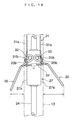
- the driving shaft 24 is slightly deformed toward the right-hand article passage 14 to eliminate the gap G, as illustrated in Fig. 16, so that the right-hand holder 20 comes in contact with the stopper 31 of the holder support 31 and is stopped or supported by the holder support 31.
- a large moment will not act on the supporting shaft 32, and a sufficient protruding amount can be ensured for the left-hand holder 20, thereby making it possible to hold the next sold article S without hinderance.
- the motor 26 is actuated at predetermined timing to rotate over the same angular distance in the opposite direction to return to a home position, causing the stopper plate 19 to pivotally return to the stop position in Fig. 12.
- the open/close plate 18 is pressed by the stopper plate 19 to return to the closed position against the urging force of the spring, and the holder 20 is pivotally moved to the retracting position by a spring force of the coil spring 33, causing the article dispensing apparatus 1 to return to the purchase waiting state as illustrated in Figs. 12 and 13.
- Fig. 17 by rotating the driving shaft 24 in the direction opposite to that of Fig. 14 (in the direction indicated by the arrow D), an article S is dispensed from the right-hand article passage 14 in a similar manner.
- the present invention is not limited to the embodiment described above but may be implemented in a variety of aspects.
- the open/close plates are separately provided for opening and closing the two article passages, respectively, any arbitrary structure may be employed for the open/close plates.
- details in structure may be modified as appropriate without departing from the spirit and scope of the present invention.
- the article dispensing apparatus for an automatic vending machine as described above has advantages such as the ability of appropriately supporting a holder for a next sold article in a simple, compact and inexpensive structure.
Landscapes
- Physics & Mathematics (AREA)
- General Physics & Mathematics (AREA)
- Vending Machines For Individual Products (AREA)
Priority Applications (2)
| Application Number | Priority Date | Filing Date | Title |
|---|---|---|---|
| JP16041097A JP3511194B2 (ja) | 1997-06-02 | 1997-06-02 | 自動販売機の商品搬出装置 |
| EP98122716A EP1006497A1 (fr) | 1997-06-02 | 1998-11-30 | Dispositif de distribution d'articles pour distributeur automatique |
Applications Claiming Priority (2)
| Application Number | Priority Date | Filing Date | Title |
|---|---|---|---|
| JP16041097A JP3511194B2 (ja) | 1997-06-02 | 1997-06-02 | 自動販売機の商品搬出装置 |
| EP98122716A EP1006497A1 (fr) | 1997-06-02 | 1998-11-30 | Dispositif de distribution d'articles pour distributeur automatique |
Publications (1)
| Publication Number | Publication Date |
|---|---|
| EP1006497A1 true EP1006497A1 (fr) | 2000-06-07 |
Family
ID=26149840
Family Applications (1)
| Application Number | Title | Priority Date | Filing Date |
|---|---|---|---|
| EP98122716A Withdrawn EP1006497A1 (fr) | 1997-06-02 | 1998-11-30 | Dispositif de distribution d'articles pour distributeur automatique |
Country Status (2)
| Country | Link |
|---|---|
| EP (1) | EP1006497A1 (fr) |
| JP (1) | JP3511194B2 (fr) |
Cited By (3)
| Publication number | Priority date | Publication date | Assignee | Title |
|---|---|---|---|---|
| EP1998295A3 (fr) * | 2007-05-31 | 2009-03-11 | Sanden Corporation | Colonne de marchandises pour distributeur automatique |
| WO2009045685A3 (fr) * | 2007-09-28 | 2009-05-22 | Coca Cola Co | Système pour faire avancer un conditionnement |
| ITNA20090078A1 (it) * | 2009-12-18 | 2011-06-19 | Marco Cervizzi | Sistema di stoccaggio, gestione e distribuzione elettromeccanico su piste autonome di farmaci o simili all'interno ed esterno di farmacie configurabile con sistema di vendita self h-24. |
Citations (1)
| Publication number | Priority date | Publication date | Assignee | Title |
|---|---|---|---|---|
| JPH10143749A (ja) * | 1996-11-07 | 1998-05-29 | Sanyo Electric Co Ltd | 自動販売機の商品搬出装置 |
-
1997
- 1997-06-02 JP JP16041097A patent/JP3511194B2/ja not_active Expired - Fee Related
-
1998
- 1998-11-30 EP EP98122716A patent/EP1006497A1/fr not_active Withdrawn
Patent Citations (1)
| Publication number | Priority date | Publication date | Assignee | Title |
|---|---|---|---|---|
| JPH10143749A (ja) * | 1996-11-07 | 1998-05-29 | Sanyo Electric Co Ltd | 自動販売機の商品搬出装置 |
Non-Patent Citations (1)
| Title |
|---|
| PATENT ABSTRACTS OF JAPAN vol. 098, no. 010 31 August 1998 (1998-08-31) * |
Cited By (4)
| Publication number | Priority date | Publication date | Assignee | Title |
|---|---|---|---|---|
| EP1998295A3 (fr) * | 2007-05-31 | 2009-03-11 | Sanden Corporation | Colonne de marchandises pour distributeur automatique |
| CN101315715B (zh) * | 2007-05-31 | 2012-07-04 | 三电有限公司 | 自动售货机的商品收纳栏 |
| WO2009045685A3 (fr) * | 2007-09-28 | 2009-05-22 | Coca Cola Co | Système pour faire avancer un conditionnement |
| ITNA20090078A1 (it) * | 2009-12-18 | 2011-06-19 | Marco Cervizzi | Sistema di stoccaggio, gestione e distribuzione elettromeccanico su piste autonome di farmaci o simili all'interno ed esterno di farmacie configurabile con sistema di vendita self h-24. |
Also Published As
| Publication number | Publication date |
|---|---|
| JPH10334330A (ja) | 1998-12-18 |
| JP3511194B2 (ja) | 2004-03-29 |
Similar Documents
| Publication | Publication Date | Title |
|---|---|---|
| US5497905A (en) | Vending machine, and release mechanism | |
| EP1006497A1 (fr) | Dispositif de distribution d'articles pour distributeur automatique | |
| JP3524780B2 (ja) | 自動販売機の商品搬出装置 | |
| CN112530084A (zh) | 自动售货机和补货方法 | |
| US6715636B2 (en) | Vending machine for dispensing cans & bottles with stop member | |
| EP1006495B1 (fr) | Appareil de stockage d'articles pour distributeur automatique | |
| EP1006496A1 (fr) | Conteneur d'articles pour distributeur automatique | |
| JP3800733B2 (ja) | 自動販売機の商品収納装置 | |
| JP2000242851A (ja) | 自動販売機 | |
| JP3403089B2 (ja) | 自動販売機の商品収納払出装置 | |
| JP3478066B2 (ja) | 自動販売機の商品収納装置 | |
| JP3478064B2 (ja) | 自動販売機の商品収納装置 | |
| EP1006494B1 (fr) | Module de stockage d'articles pour distributeur automatique | |
| JP3478065B2 (ja) | 自動販売機の商品収納装置 | |
| JP3670862B2 (ja) | 自動販売機の商品収納払出装置 | |
| US20030146238A1 (en) | Vending machine for dispensing cans & bottles with elevator assembly | |
| JP2685231B2 (ja) | 自動販売機の商品搬出装置 | |
| JP2000076532A (ja) | 自動販売機の商品収納払出装置 | |
| JP2001101496A (ja) | 自動販売機の商品取出口装置 | |
| JP2002083358A (ja) | 自動販売機の商品払出装置における盗難防止構造 | |
| JP5434553B2 (ja) | 自動販売機 | |
| JP4319063B2 (ja) | 自動販売機の商品取出口構造 | |
| EP1300812A2 (fr) | Distributeur | |
| JP2007286748A (ja) | ボトル商品の自動販売機 | |
| JPH076877U (ja) | 自動販売機 |
Legal Events
| Date | Code | Title | Description |
|---|---|---|---|
| PUAI | Public reference made under article 153(3) epc to a published international application that has entered the european phase |
Free format text: ORIGINAL CODE: 0009012 |
|
| AK | Designated contracting states |
Kind code of ref document: A1 Designated state(s): DE FR GB IT |
|
| AX | Request for extension of the european patent |
Free format text: AL;LT;LV;MK;RO;SI |
|
| 17P | Request for examination filed |
Effective date: 20000718 |
|
| AKX | Designation fees paid |
Free format text: DE FR GB IT |
|
| RAP1 | Party data changed (applicant data changed or rights of an application transferred) |
Owner name: FUJI ELECTRIC CO., LTD. |
|
| STAA | Information on the status of an ep patent application or granted ep patent |
Free format text: STATUS: THE APPLICATION HAS BEEN WITHDRAWN |
|
| 18W | Application withdrawn |
Effective date: 20050831 |