EP1006498A1 - Machine de jeu - Google Patents
Machine de jeu Download PDFInfo
- Publication number
- EP1006498A1 EP1006498A1 EP99122769A EP99122769A EP1006498A1 EP 1006498 A1 EP1006498 A1 EP 1006498A1 EP 99122769 A EP99122769 A EP 99122769A EP 99122769 A EP99122769 A EP 99122769A EP 1006498 A1 EP1006498 A1 EP 1006498A1
- Authority
- EP
- European Patent Office
- Prior art keywords
- detection
- main control
- signal transmission
- control
- peripheral
- Prior art date
- Legal status (The legal status is an assumption and is not a legal conclusion. Google has not performed a legal analysis and makes no representation as to the accuracy of the status listed.)
- Granted
Links
- 230000008054 signal transmission Effects 0.000 claims abstract description 48
- 230000002093 peripheral effect Effects 0.000 claims abstract description 33
- 238000001514 detection method Methods 0.000 claims description 84
- 230000008901 benefit Effects 0.000 claims description 4
- 238000012360 testing method Methods 0.000 abstract description 9
- 239000000758 substrate Substances 0.000 description 31
- 230000001276 controlling effect Effects 0.000 description 14
- 238000007689 inspection Methods 0.000 description 10
- 238000010586 diagram Methods 0.000 description 8
- 230000007246 mechanism Effects 0.000 description 8
- 241000722921 Tulipa gesneriana Species 0.000 description 7
- 230000000694 effects Effects 0.000 description 5
- 230000006870 function Effects 0.000 description 5
- 230000009471 action Effects 0.000 description 4
- 239000004973 liquid crystal related substance Substances 0.000 description 4
- 230000001105 regulatory effect Effects 0.000 description 3
- 238000010276 construction Methods 0.000 description 2
- 238000009434 installation Methods 0.000 description 2
- 238000012545 processing Methods 0.000 description 2
- 230000000717 retained effect Effects 0.000 description 2
- 230000000712 assembly Effects 0.000 description 1
- 238000000429 assembly Methods 0.000 description 1
- 230000005540 biological transmission Effects 0.000 description 1
- 238000013461 design Methods 0.000 description 1
- 238000011161 development Methods 0.000 description 1
- 238000007599 discharging Methods 0.000 description 1
- 238000005516 engineering process Methods 0.000 description 1
- 239000011521 glass Substances 0.000 description 1
- 230000006872 improvement Effects 0.000 description 1
- 238000004519 manufacturing process Methods 0.000 description 1
- 238000000034 method Methods 0.000 description 1
- 238000007639 printing Methods 0.000 description 1
- 230000000452 restraining effect Effects 0.000 description 1
- 239000004576 sand Substances 0.000 description 1
- 230000007704 transition Effects 0.000 description 1
Images




Classifications
-
- G—PHYSICS
- G07—CHECKING-DEVICES
- G07F—COIN-FREED OR LIKE APPARATUS
- G07F17/00—Coin-freed apparatus for hiring articles; Coin-freed facilities or services
- G07F17/32—Coin-freed apparatus for hiring articles; Coin-freed facilities or services for games, toys, sports, or amusements
-
- G—PHYSICS
- G07—CHECKING-DEVICES
- G07F—COIN-FREED OR LIKE APPARATUS
- G07F17/00—Coin-freed apparatus for hiring articles; Coin-freed facilities or services
- G07F17/32—Coin-freed apparatus for hiring articles; Coin-freed facilities or services for games, toys, sports, or amusements
- G07F17/3202—Hardware aspects of a gaming system, e.g. components, construction, architecture thereof
Definitions
- the invention relates to an improvement of a game machine, such as a ball-flicking type including a so-called “Pachinko”, “Arrange-ball”, and “Majong-ball", a reel-rotating type called “Pachi-slot”, or a slot machine.
- a game machine such as a ball-flicking type including a so-called “Pachinko”, “Arrange-ball”, and “Majong-ball”, a reel-rotating type called “Pachi-slot”, or a slot machine.
- This kind of game machines allow a special pattern indication device using liquid crystal display, CRT, or a mechanical reel to perform changeable indication corresponding to changes of progress of games, for example, occurrence of a ball's falling into a special operation-start hole, or allow a lamp(s) and/or an amplifier(s) to make unique performance effects.
- Changeable indication or unique performance effects become more advanced or complicated corresponding to development of microcomputer technology and advanced needs from players in recent years.
- a main CPU which adapted for main control controlling progress of play such as determination of a big bonus winning
- at least one subordinate CPU which is for indicating patterns and controlling predetermined output means, in order to enable dispersed processing.
- game machine comprises a main control substrate including a main CPU and at least one peripheral controlling substrate formed separately from the main control substrate and including a subordinate CPU, and a signal transmission means such as wiring connecting the substrates to transmit data.
- the substrates are generally separated with specific functions and connected via a signal transmission means such as wirings. Furthermore, a detection means detecting conditions that bring changes to progress of play, for example, a special operation-start switch, is provided at a point for making the detection and is connected to the main control substrate via a signal transmitting means such as wiring.
- a detection means detecting conditions that bring changes to progress of play, for example, a special operation-start switch, is provided at a point for making the detection and is connected to the main control substrate via a signal transmitting means such as wiring.
- the signal transmission means such as wiring may be often stretched through or exposed to the air although the wirings have outer sheaths, does not expose the conductive members, are properly collected at the middle on an intervening substrate or retained by a harness or a cable cramp, so that it is unlikely that a long wiring solely suspends.
- the wirings are possibly broken at its outer sheaths by legs of IC projecting from the substrate, a pointed tool, or any of various protuberances in the working environment, thereby causing short-circuit or breaking of wire.
- the wirings could be torn off by an inadvertent handling upon removing or transportation.
- the signal transmission means such as wiring which can be easily accessible or touched from the outside has a fear to suffer troubles by pranks or unlawful actions.
- An object of the present invention is to provide a game machine wherein a signal transmission path consecutively extending from a signal start part to a signal arrival part via wirings can be inspected without necessity of taking apart the machine body.
- the invention defined claim 1 is a game machine comprising, as exemplified in Fig. 1, a main control means 1 for controlling progress of play, a peripheral means 2, which a control signal from the main control means 1 is input into to actuate an output means 20 to be controlled, and a control signal transmission means 3 connecting the main control means and the peripheral means, wherein there is provided a control signal takeout means 4 which takes out control signals transmitted by the control signal transmission means to the outside at a point after a connection to the peripheral means.
- the output means 20 to be controlled may be a special pattern indication device using a liquid crystal display, CRT, mechanical reels, dots-type reels to changeably show patterns consisting of numbers, pictures, etc., to cause players to expect a big winning that opens a large winning hole.
- Those to be controlled may include an ordinary pattern indication device using 7 segments LED to changeably show patterns of numbers, signs, etc., to cause players to expect opening of a tulip-type advantageous mechanism, a visible indication device such as LED, LCD, lamps arranged in the play zone, a sound output device such as amplifiers providing sound effects, BGM, sounds of error, or buzzers, or a payoff device for balls or tokens.
- the main control means 1 may comprise at least one micro-processor in most cases.
- the peripheral means 2 when bears a complicated control as of the special pattern indication may comprise at least one micro-processor, but does not so when the output means 20 to be controlled is relatively simple in construction and uses a separate substrate in consideration of spaces. In other words, it is enough for the peripheral means 2 to only bear service of transmitting a control signal from the main control means 1 to the output means 20.
- the control signal transmission means 3 may include a single or plural wiring cable(s), flat cable(s), flexible printed wiring substrate.
- the control signal takeout means 4 may use such structures of terminal type such as connectors, receptacles, or direct-formation type such as pin, lands projecting on the substrate. Points where signals are taken out may be input connectors serving as a connection to the peripheral means 2, a patterned part on the substrate extended from the input connectors, and I/O part of CPU provided on the peripheral means 2.
- the invention defined in claim 2 is directed to a Pachinko machine and has an object to enable inspection of wiring at an important part having a large influence on the profit of players.
- the game machine provides that the output means 20 to be controlled comprises a special pattern indication device for changeably showing a number of patterns including a big bonus winning or losing patterns, and the peripheral means 2 comprises an indication control device for controlling the special pattern indication device.
- the invention defined in claim 3 is a game machine comprising, as exemplified in Fig. 2, a detection means 5 detecting conditions which bring changes to progress of the game, a main control means 1 controlling the progress of the game in accordance with detection signals from the detection means, and a detection signal transmission means 6 connecting the detection means and the main control means, wherein there is provided a detection signal takeout means 7 which takes out detection signals transmitted by the detection signal transmission means to the outside at a point after a connection to the main control means.
- the detection means 5 in case of Pachinko machines may be a special operation start switch for starting selection between a big winning to open a large winning hole or not so, a gate switch for actuating selection between opening a tulip-type advantageous mechanism or not so, a count switch for regulating a maximum of winning balls, or a winning-ball detecting switch.
- Variation of the detection signal transmission means 6 and detection signal takeout means 7 is the same as the foregoing explanation for the transmission and takeout means 3 and 4 for control signals.
- the invention defined in claim 4 is directed to a Pachinko machine and has an object to enable inspection of wiring at an important part having large influence on benefits of players.
- the detection means 5 may comprise a detection switch in relation to a big winning control to give players a large profit.
- the detection switch may cover a special-operation start switch for starting selection between a big winning or not, and a count switch for regulating a maximum of winning balls in each round upon a big winning.
- the invention defined in claim 5 is a combination of claims 1 and 3 to enable inspection both of input and output sides with respect to the main control means 1 inclusive of wirings when a specific output means 20 is controlled by the main control means 1.
- the game machine does, as exemplified in Fig.
- a detection means 5 detecting conditions which bring changes to progress of the game
- a main control means 1 controlling the progress of the game in accordance with detection signals from the detection means
- a peripheral means 2 which a control signal from the main control means is input into to actuate an output means 20 to be controlled
- a control signal transmission means 3 connecting the main control means and the peripheral means
- a detection signal transmission means 6 connecting the detection means and the main control means, wherein there are provided a control signal takeout means 4, which takes out control signals transmitted by the control signal transmission means to the outside at a point after a connection to the peripheral means, and a detection signal takeout means 7, which takes out detection signals transmitted by the detection signal transmission means to the outside at a point after a connection to the main control means.
- the invention defined in claim 6 is directed to a Pachinko machine and has an object to enable inspection of wiring at an important part having a large influence on benefit of players, and enable the inspection to be performed at both of input and output side of the main control means 1.
- the output means 20 to be controlled comprises a special pattern indication device for changeably showing a number of patterns including a big bonus winning or losing patterns
- the peripheral means 2 comprises an indication control device for controlling the special pattern indication device
- the detection means 5 comprises a detection switch in relation to a big bonus winning control.
- the invention defined in claim 1 can simply and easily inspect the control signal transmission means 3 merely by examining signals form the control signal takeout means 4 as shown in Fig. 1.
- the control signal takeout means 4 takes out signals at a point after a connection of the control signal transmission means 3 to the peripheral means 2, so that it covers completely the entire length of the control signal transmission means 3 and can inspect short-circuit or breaking of wire thereon.
- the control signal takeout means 4 which takes out signals to the outside can connect with a measuring device such as a tester, oscilloscope, digital analyzer, or a testing tool such as a personal computer, an exclusively usable test monitor to easily examine levels, its order, timing of control signals and compare and check the examined control signals and actual operation of the output means 20. Accordingly, control signals from the main control means 1 inclusive of the part of control signal transmission means 3 can be inspected, thereby improving function of examining damages and troubles.
- the invention defined in claim 2 enables easy or simple inspection of the control signal transmission means 3 used for a part controlling the special pattern indication device particularly important for the Pachinko machine.
- signals taken out by the control signal takeout means 4 are control signals which are transmitted from the main control means 1 via control signal transmission means 3 and are data at a level of commands before being decoded to be developed as actual micro indication signals by the indication control device.
- the signals may be checked for enabling plain and clear inspection of the game machine in view of programming specification.
- the invention defined in claim 3 provides easy inspection of the detection signal transmission means 6 merely by examining signals from the detection signal takeout means 7.
- the detection signal takeout means 7 which takes out signals at a point after a connection of the detection signal transmission means 6 to the main control means 1 can completely cover the entire length of detection signal transmission means 6 and examine short-circuit and breaking of breaking of wire thereon.
- the detection signal takeout means 7 which takes out signals to the outside can connect with a measuring device such as a tester, oscilloscope, digital analyzer, or a testing tool such as a personal computer,an exclusively usable test monitor to easily examine levels or other factors of detection signals and compare and check the examined detection signals and actual operation of the detection means 5. Accordingly,detection signals from the detection means 5 inclusive of the part of detection signal transmission means 6 can be inspected, thereby improving function of examining damages and troubles.
- the invention defined in claim 4 enables easy inspection of detection switch, inclusive of the detection signal transmission means 6, in relation to a big winning control particularly important for the Pachinko machine. A large benefit is given to players upon occurrence of a big winning.
- the big winning detection switch has hitherto undergone unlawful actions.
- the present invention allows the main control means 1 to inspect the big winning detection switch easily and clearly, thereby enabling simple checking unlawful actions and providing an effect of restraining any latent criminal.
- the invention defined in claim 5 does, as seen in Fig. 3, enable easy inspection of detection signals and control signals at both of input and output sides with respect to the main control means 1 inclusive of signal transmission means by examining detection signals from the detection signal takeout means 7 and control signals form the control signal takeout means 4.
- progress of play is controlled on the basis of detection signals input into the main control means 1, and the output means 20 is actuated by inputting control signals from the main control means 1 into the peripheral means 2.
- signals in relation to a series of controlling can be monitored at the input and output side with respect to the main control means 1.
- checking of signals at the input and output sides are performed including the signal transmission means 6 and 3.
- a series of control system for a specific output means 20 can be excellently inspected.
- the invention defined in claim 6 provides that a series of control system in relation to a big winning control particularly important for the Pachinko machine can be excellently performed at both of input and output sides of the main control means 1 inclusive of signal transmission means 6 and 3.
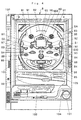
- Fig. 4 shows a Pachinko machine 8 which the present invention is applied to and comprises a game board 80 placed inside a glass window and having a guide rail 81, which defines a game zone and guides flicked balls, a number of pegs 82 mostly omitted except the top ones, a special pattern indication device 83, which uses a liquid crystal display to changeably show on the screen a special pattern formed by left-hand, central and right-hand lines including numbers and signs, a special operation start hole 84 comprising a tulip-type advantageous mechanism, which actuates the changeable indication of the indication device 83 and starts selection of provision of a big winning with a stopped pattern of the same pictures in the left-hand, central and right-hand lines, a big winning hole 85 to open upon the big winning, winning holes 86 laterally of the big winning 85, sidewise winning holes 87 and 88, side lamps 89, 90, lamped windmills 91, ordinary windmills 92, go-through type passage 93 above the advantageous mechanism, and
- top winning hole 95 there are provided top winning hole 95, ordinary pattern indication device 96 consisting of 7 segments LED, and ordinary pattern memory LED960, which memorizes four times at maximum initialization of changes of ordinary patterns when complexed.
- left-hand and right-hand gates 97 and 98 causing the ordinary pattern indication device 96 to make changeable indication.
- special pattern memory LED830 which memorizes four times at maximum initialization of changes of special patterns when complexed.
- a tray 99 for the balls there are provided a tray 99 for the balls, a subordinate tray 100 for receiving balls flown from the inside and the upper tray 99, and a launching handle 101 for discharging balls into the play zone on the game board 80 by actuation of an accommodated launching solenoid.
- 102 is a unit for pre-paid cards, i.e., a so-called "CR sand", that supplies onto the upper tray 99 balls in number in an extent defined by data memorized in the pre-paid card to be inserted into a card slot 103.
- a lever 104 at the launching handle 101 may be turned clockwise to shoot a specific ball fed from the upper tray 99 into the play zone on the game board.
- 105 is a hole collecting balls becoming lost.
- the tulip at the start hole 84 is opened in a predetermined time to provide players with increased chances of winning through the special operation start.
- Time to open may be longer or shorter, and the tulip may be closed when an additional or predetermined number of winning at the start hole 84 occurs.
- Time to open is determined by values of winning conditions counter that makes plus one, due to selection actuated by every ball launched when a pair of ball detection switches a1, a2 in front of the launching solenoid detect a launched ball, and a return ball detection switch a3 does not detect any returning ball not arriving at the play zone.
- tulip opening time is 5 seconds, and 0.2 sec when lower than the same.
- the winning condition counter subtracts one from the value whenever a winning occurs at the operation-start hole 84.
- frequency of winning at the special operation start 84 is low, a maximum opening time of tulip due to winning the ordinary pattern is set longer to provide amendment function for keeping constant a rate of winning at the operation-start hole.
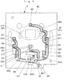
- Fig. 5 shows a path of balls on the rear side of the game board 80.
- Balls falling into the winning holes 86, 87, 88 and 95 flow down gutters 861, 862, 871, 872, 881, 882 and 950 to a collecting gutter 800.
- a ball in an operation-start 84 pass an operation start switch b1 and go through the gutter 840 to the collecting gutter 800.
- a ball in the big winning hole 85 passes a count switch b2 and go through the gutter 850 to the gutter 800.
- Balled collected at the gutter 800 first pass a winning ball detection switch b3 and discharged through ball exit 801 to an installation for mounting the Pachinko machines.
- b11 is a motor for opening and closing an attacker 85, b12 solenoid for opening and closing tulip at the operation-start hole 84, and a9 and a10 gate left-hand switch and gate right-hand switch which detect balls passing the left-hand and right-hand gates 97,98 to actuate changeable indication of the ordinary pattern indication device 96 and selection between the winning and losing.
- Balls obtainable for every winning in the operation-start 84 and ordinary holes 86, 87, 88 and 95 may be six, and that in case of the big winning hole 85 may be 15.
- the count switch b2 has a function of regulating the maximum winning number to close the big winning hole 85 when the number of winning at the hole 85 becomes 10, even before the maximum opening time 30 seconds elapses in each round of big winning.
- the counter switch b2 allows transition to the next round, i.e., continuation of rounds when any one winning occurs at a V-winning timing set in an initial 5 seconds and 5 seconds from 15th to 20th second after start opening the big winning hole 85 during its maximum open time 30 seconds. Rounds to be continued that allowed for each big winning is 16 times at maximum.
- Fig. 6 shows a mechanism at the there of the Pachinko machine 8 provided with a container 910 for balls supplied from the installation, lining gutter 920,flow-regulating sprocket 930, flow-down gutter 940, and payoff device 9 having winning ball device 900.
- the winning ball device 900 is provided with a payoff solenoid 952 serving as an output means to operate a sprocket type control member 951.
- the sprocket type control member 951 is retained by a movable member 953 of the solenoid 952 to stop paying off balls, and the movable member 953 may be taken up to make free the control member 951, thereby performing paying off balls.
- Balls are counted by a pair of ball number detection switches 954, 955 having light emitting and receiving parts, respectively, thereby providing a predetermined number, 15 or 6, of prize balls.
- 941 is a flow down gutter extended from an outlet of the winning ball device 900, 942 a diverged gutter guiding balls flown over from the upper tray 99 to the lower tray 100, and 980 a gutter for flowing balls from the container 910.
- Fig. 6, 1 is a main control means for controlling progress of play, which centrally performs various controls of, such as changeable indication of special pattern indication device 83 following the operation-start winning, opeing of the big winning hole 85, changeable indication of ordinary pattern indication device 96 following ball's flowing through the left-hand and right-hand gates, opening of tulip type advantageous mechanism, prize balls payoff due to winning, control of various lamps, and sounds from amplifiers.
- various controls of such as changeable indication of special pattern indication device 83 following the operation-start winning, opeing of the big winning hole 85, changeable indication of ordinary pattern indication device 96 following ball's flowing through the left-hand and right-hand gates, opening of tulip type advantageous mechanism, prize balls payoff due to winning, control of various lamps, and sounds from amplifiers.
- Fig. 6, 2 is a peripheral means which receives a control signal from the main control means 1 to actuate a specific output means 20, and includes an indication control device 21 comprising a liquid crystal control substrate for controlling the special pattern indication device 83 as the output means 20, an ordinary pattern substrate 22 transmitting signals to the ordinary pattern indication device 96 as output means 20, and a frame substrate 23 for controlling the winning ball device 900 as output means 20.
- an indication control device 21 comprising a liquid crystal control substrate for controlling the special pattern indication device 83 as the output means 20, an ordinary pattern substrate 22 transmitting signals to the ordinary pattern indication device 96 as output means 20, and a frame substrate 23 for controlling the winning ball device 900 as output means 20.
- a substrate for control launching such as solenoid and intervening substrates for relaying signals.
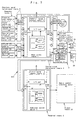
- Fig. 7 is a schematic block diagram showing corelation of connection between the main control means 1 and the peripheral means 2.
- Detection means 5 detecting conditions that bring changes to progress of game, such as changeable indication of the special pattern or ordinary pattern are connected to an input connector IN of the main control means 1 via detection signal transmission means 6.
- Operation-start hole switch b1, count switch b2, winning ball detection switch b3, gate left-hand switch a9, gate right-hand switch a10 each constituting the detection means 5 are connected to the main control means 1 with their wirings being supported on a first intervening substrate 601.
- Launched ball detection right-hand switch a1, left-hand switch a2, return ball detection switch a3, each constituting the detection means 5 are connected to the main control means 1 with their wirings being supported on a second intervening substrate 602.
- the main control means 1 is connected at its output connector OUT with the indication control device 21, ordinary pattern substrate 22 and frame substrate 23 constituting a peripheral means 2 through a control signal transmission means 3.
- the middle part of the control signal transmission means 3 extending to the ordinary pattern substrate 22 together with solenoid b12 of the tulip type advantageous mechanism and special pattern memory LED 830 are relayed by the first intervening substrate 601.
- An intermediate part of signal transmission means extending to the motor b11 of big winning hole is relayed on the third intervening substrate 603.
- the part of signal transmission means indicated by hollow arrows comprises a single flexible printed substrate using a flexible film with wiring patterns at input and output sides integrally formed by printing.
- the indication control device 21 and frame substrate 23 of the main control means 1 and peripheral means 2 are provided with a micro-processor part including central processing unit CPU, read only memory ROM, and random access memory RAM and are connected to the input connector IN and output connector OUT through I/O part that exchanges data with bus line.
- a micro-processor part including central processing unit CPU, read only memory ROM, and random access memory RAM and are connected to the input connector IN and output connector OUT through I/O part that exchanges data with bus line.
- Fig. 8 shows a first embodiment of a control signal takeout means 4, which takes out control signals transmitted by the control signal transmission means 3 at a point after a connection to a peripheral means 2 such as a indication control device 21 to the outside, or a detection signal takeout means 7, which takes out detection signals transmitted by detection signal transmission means 6 at a point after a connection to the main control means 1.
- a signal takeout terminal is integrally form at the connector IN part to connect with a measuring device or testing tools.
- Fig. 9 shows a second embodiment of the control signal takeout means 4 or detection signal takeout means 7.
- pins, through-holes, lands, or connectors may be provided on the way of wiring pattern extending from output, for example, of input buffer, forming the I/O part, thereby enabling connection with measuring devices or testing tools.
- Fig. 10 shows a third embodiment of the control signal takeout means 4 or detection signal takeout means 7.
- signals which first input in CPU and taken out through output port can be monitored.
- Pins, through-holes, lands, connectors may be provided on the way of wiring pattern extending from the output port, thereby enabling connection with measuring devices or testing tools.
- the control signal takeout means 4 and detection signal takeout means 7 do not need the same construction.
- the structures of Figs. 8 to 10 may be used in proper combination.
- the control signal takeout means 4 may use a structure of Fig. 9 while the detection signal takeout means 7 may be structured as in Fig. 8.
- pins, through holes, lands, connectors may be provided on the way of wiring pattern extending from the input connector IN, thereby enabling connection with measuring devices or testing tools.
- control of various lamps and sounds from amplifiers may be carried out as the peripheral means with respect to the main control means with the present invention applied to the parts for controlling lamps or sounds.
- the above explanation is given with referring to an example of Pachinko machine.
- the invention may be applicable also to other ball-flicking type machines such as arrange-ball, majong ball, or reel-rotation type machine such as Pachi-sulo, or a slot machine wherein token payoff device or reel control device may be conceived as the peripheral means with respect to the main control means.
Landscapes
- Physics & Mathematics (AREA)
- General Physics & Mathematics (AREA)
- Pinball Game Machines (AREA)
- Memory System Of A Hierarchy Structure (AREA)
- Slot Machines And Peripheral Devices (AREA)
Applications Claiming Priority (2)
| Application Number | Priority Date | Filing Date | Title |
|---|---|---|---|
| JP10345350A JP2000167213A (ja) | 1998-12-04 | 1998-12-04 | 遊技機 |
| JP34535098 | 1998-12-04 |
Publications (2)
| Publication Number | Publication Date |
|---|---|
| EP1006498A1 true EP1006498A1 (fr) | 2000-06-07 |
| EP1006498B1 EP1006498B1 (fr) | 2004-02-11 |
Family
ID=18376012
Family Applications (1)
| Application Number | Title | Priority Date | Filing Date |
|---|---|---|---|
| EP99122769A Expired - Lifetime EP1006498B1 (fr) | 1998-12-04 | 1999-11-16 | Machine de jeu |
Country Status (7)
| Country | Link |
|---|---|
| US (1) | US6416053B1 (fr) |
| EP (1) | EP1006498B1 (fr) |
| JP (1) | JP2000167213A (fr) |
| AT (1) | ATE259526T1 (fr) |
| AU (1) | AU759167B2 (fr) |
| DE (1) | DE69914708T2 (fr) |
| ZA (1) | ZA997207B (fr) |
Families Citing this family (10)
| Publication number | Priority date | Publication date | Assignee | Title |
|---|---|---|---|---|
| US6854729B2 (en) * | 2000-11-15 | 2005-02-15 | Kabushiki Kaisha Sankyo | Play media shooting machine with improved stop control |
| JP2003117243A (ja) * | 2001-10-17 | 2003-04-22 | Konami Co Ltd | ゲーム進行制御プログラム、ゲーム進行制御方法及びビデオゲーム装置 |
| US6939225B2 (en) * | 2002-06-27 | 2005-09-06 | Igt | Gaming device having bonus game with multiple moving objects within partitionable channels |
| US20040166932A1 (en) * | 2003-02-20 | 2004-08-26 | Rex Lam | Method and apparatus for controlling a display on a light device in a gaming unit |
| US20040166917A1 (en) * | 2003-02-20 | 2004-08-26 | Rex Lam | USB light controller for controlling a display on a light device in a gaming unit |
| US20070218969A1 (en) * | 2006-03-14 | 2007-09-20 | Aruze Corp. | Gaming machine |
| JP5232946B2 (ja) * | 2008-02-28 | 2013-07-10 | 株式会社高尾 | 弾球遊技機 |
| JP4885296B1 (ja) * | 2010-09-01 | 2012-02-29 | 株式会社コナミデジタルエンタテインメント | ボール抽選装置 |
| US8382575B2 (en) | 2010-09-17 | 2013-02-26 | Speilo Manufacturing ULC | System and method for identifying errors in slot machine and video lottery terminal games |
| US10475288B2 (en) * | 2017-12-13 | 2019-11-12 | Zynga Inc. | Enhancing a user interface of a computer-implemented game to generate slot-machine-style pay lines |
Citations (6)
| Publication number | Priority date | Publication date | Assignee | Title |
|---|---|---|---|---|
| US4072930A (en) * | 1974-09-13 | 1978-02-07 | Bally Manufacturing Corporation | Monitoring system for use with amusement game devices |
| GB2124418A (en) * | 1982-05-24 | 1984-02-15 | Coin Controls | Monitoring system for gaming machines |
| DE3820868A1 (de) * | 1988-01-13 | 1989-07-27 | Nsm Apparatebau Gmbh Kg | System zum abruf von spielgeraetedaten |
| DE4140450A1 (de) * | 1991-12-05 | 1993-06-09 | Bally Wulff Automaten Gmbh, 1000 Berlin, De | Anordnung zur datenfernuebertragung von und zu muenzbetaetigten unterhaltungsgeraeten |
| EP0579449A2 (fr) * | 1992-07-08 | 1994-01-19 | Kabushiki Kaisha Universal | Machine de jeu et méthode pour détecter des fraudes dans cette machine |
| DE4402101A1 (de) * | 1994-01-04 | 1995-08-10 | Nsm Ag | Steuereinheit für Unterhaltungsspielgeräte mit oder ohne Gewinnmöglichkeit |
Family Cites Families (3)
| Publication number | Priority date | Publication date | Assignee | Title |
|---|---|---|---|---|
| ES531967A0 (es) * | 1983-05-02 | 1985-09-16 | Ainsworth Nominees Pty Ltd | Perfeccionamientos en los sistemas de maquinas de juego |
| WO1994019076A1 (fr) * | 1993-02-17 | 1994-09-01 | Kabushiki Kaisha Ace Denken | Systeme de maison de jeux utilisant un support memoire |
| JPH08318025A (ja) * | 1995-05-26 | 1996-12-03 | Sankyo Kk | 遊技機 |
-
1998
- 1998-12-04 JP JP10345350A patent/JP2000167213A/ja active Pending
-
1999
- 1999-11-16 AT AT99122769T patent/ATE259526T1/de active
- 1999-11-16 EP EP99122769A patent/EP1006498B1/fr not_active Expired - Lifetime
- 1999-11-16 DE DE1999614708 patent/DE69914708T2/de not_active Expired - Lifetime
- 1999-11-18 AU AU59556/99A patent/AU759167B2/en not_active Ceased
- 1999-11-19 ZA ZA9907207A patent/ZA997207B/xx unknown
- 1999-11-29 US US09/449,563 patent/US6416053B1/en not_active Expired - Lifetime
Patent Citations (6)
| Publication number | Priority date | Publication date | Assignee | Title |
|---|---|---|---|---|
| US4072930A (en) * | 1974-09-13 | 1978-02-07 | Bally Manufacturing Corporation | Monitoring system for use with amusement game devices |
| GB2124418A (en) * | 1982-05-24 | 1984-02-15 | Coin Controls | Monitoring system for gaming machines |
| DE3820868A1 (de) * | 1988-01-13 | 1989-07-27 | Nsm Apparatebau Gmbh Kg | System zum abruf von spielgeraetedaten |
| DE4140450A1 (de) * | 1991-12-05 | 1993-06-09 | Bally Wulff Automaten Gmbh, 1000 Berlin, De | Anordnung zur datenfernuebertragung von und zu muenzbetaetigten unterhaltungsgeraeten |
| EP0579449A2 (fr) * | 1992-07-08 | 1994-01-19 | Kabushiki Kaisha Universal | Machine de jeu et méthode pour détecter des fraudes dans cette machine |
| DE4402101A1 (de) * | 1994-01-04 | 1995-08-10 | Nsm Ag | Steuereinheit für Unterhaltungsspielgeräte mit oder ohne Gewinnmöglichkeit |
Also Published As
| Publication number | Publication date |
|---|---|
| EP1006498B1 (fr) | 2004-02-11 |
| ATE259526T1 (de) | 2004-02-15 |
| DE69914708T2 (de) | 2005-01-13 |
| AU759167B2 (en) | 2003-04-10 |
| DE69914708D1 (de) | 2004-03-18 |
| AU5955699A (en) | 2000-06-08 |
| US6416053B1 (en) | 2002-07-09 |
| ZA997207B (en) | 2000-05-22 |
| JP2000167213A (ja) | 2000-06-20 |
Similar Documents
| Publication | Publication Date | Title |
|---|---|---|
| US6585589B2 (en) | Lottery game/gaming device interface | |
| EP1006498B1 (fr) | Machine de jeu | |
| JP2009297345A (ja) | 遊技台の基板、およびこの基板を備える遊技台 | |
| US6827647B1 (en) | Gaming machine coin handling system with dedicated local microcontroller | |
| JP2004121375A (ja) | 遊技機 | |
| JP2000300813A (ja) | 遊技機 | |
| JPH11164950A (ja) | パチンコ遊技機の不正入賞防止装置 | |
| JPH09313712A (ja) | 遊技機 | |
| JP4747407B2 (ja) | 遊技機 | |
| JPH03195580A (ja) | 遊技球封入式パチンコ機 | |
| JP2001062050A (ja) | 遊技機 | |
| JP4258902B2 (ja) | 遊技機 | |
| JP2000308747A (ja) | 遊技機 | |
| JP2000218012A (ja) | 遊技機 | |
| JP4001755B2 (ja) | 遊技機 | |
| JPH0654947A (ja) | 遊技機および遊技情報収集装置 | |
| JP4082804B2 (ja) | 弾球遊技機 | |
| JP5398080B2 (ja) | 弾球遊技機 | |
| JP2004215874A (ja) | 遊技機 | |
| JP3860975B2 (ja) | 遊技機 | |
| JPH10286357A (ja) | 遊技機 | |
| JP2000217985A (ja) | 遊技機 | |
| JP4433075B2 (ja) | 遊技機 | |
| JP2001334050A (ja) | 遊技機 | |
| JP2001149610A (ja) | 遊技制御基板及びその検査方法 |
Legal Events
| Date | Code | Title | Description |
|---|---|---|---|
| PUAI | Public reference made under article 153(3) epc to a published international application that has entered the european phase |
Free format text: ORIGINAL CODE: 0009012 |
|
| AK | Designated contracting states |
Kind code of ref document: A1 Designated state(s): AT CH DE FR GB LI |
|
| AX | Request for extension of the european patent |
Free format text: AL;LT;LV;MK;RO;SI |
|
| 17P | Request for examination filed |
Effective date: 20000913 |
|
| AKX | Designation fees paid |
Free format text: AT CH DE FR GB LI |
|
| 17Q | First examination report despatched |
Effective date: 20020111 |
|
| GRAH | Despatch of communication of intention to grant a patent |
Free format text: ORIGINAL CODE: EPIDOS IGRA |
|
| GRAS | Grant fee paid |
Free format text: ORIGINAL CODE: EPIDOSNIGR3 |
|
| GRAA | (expected) grant |
Free format text: ORIGINAL CODE: 0009210 |
|
| AK | Designated contracting states |
Kind code of ref document: B1 Designated state(s): AT CH DE FR GB LI |
|
| REG | Reference to a national code |
Ref country code: GB Ref legal event code: FG4D |
|
| REG | Reference to a national code |
Ref country code: CH Ref legal event code: EP |
|
| REF | Corresponds to: |
Ref document number: 69914708 Country of ref document: DE Date of ref document: 20040318 Kind code of ref document: P |
|
| REG | Reference to a national code |
Ref country code: CH Ref legal event code: NV Representative=s name: E. BLUM & CO. PATENTANWAELTE |
|
| ET | Fr: translation filed | ||
| PLBE | No opposition filed within time limit |
Free format text: ORIGINAL CODE: 0009261 |
|
| STAA | Information on the status of an ep patent application or granted ep patent |
Free format text: STATUS: NO OPPOSITION FILED WITHIN TIME LIMIT |
|
| 26N | No opposition filed |
Effective date: 20041112 |
|
| REG | Reference to a national code |
Ref country code: CH Ref legal event code: PFA Owner name: ARUZE CO., LTD. Free format text: ARUZE CO., LTD.#1-25, ARIAKE 3-CHOME, KOTO-KU#TOKYO 135-0063 (JP) -TRANSFER TO- ARUZE CO., LTD.#1-25, ARIAKE 3-CHOME, KOTO-KU#TOKYO 135-0063 (JP) |
|
| PGFP | Annual fee paid to national office [announced via postgrant information from national office to epo] |
Ref country code: AT Payment date: 20101112 Year of fee payment: 12 |
|
| PGFP | Annual fee paid to national office [announced via postgrant information from national office to epo] |
Ref country code: CH Payment date: 20111123 Year of fee payment: 13 Ref country code: FR Payment date: 20111130 Year of fee payment: 13 |
|
| REG | Reference to a national code |
Ref country code: CH Ref legal event code: PFA Owner name: UNIVERSAL ENTERTAINMENT CORPORATION Free format text: ARUZE CO., LTD.#1-25, ARIAKE 3-CHOME, KOTO-KU#TOKYO 135-0063 (JP) -TRANSFER TO- UNIVERSAL ENTERTAINMENT CORPORATION#3-7-25, ARIAKE, KOTO-KU#135-0063 TOKYO (JP) |
|
| REG | Reference to a national code |
Ref country code: CH Ref legal event code: PK Ref country code: CH Ref legal event code: PK Free format text: BERICHTIGUNG INHABER |
|
| REG | Reference to a national code |
Ref country code: DE Ref legal event code: R082 Ref document number: 69914708 Country of ref document: DE Representative=s name: KLUNKER, SCHMITT-NILSON, HIRSCH, DE |
|
| REG | Reference to a national code |
Ref country code: DE Ref legal event code: R082 Ref document number: 69914708 Country of ref document: DE Representative=s name: KLUNKER, SCHMITT-NILSON, HIRSCH, DE Effective date: 20120423 Ref country code: DE Ref legal event code: R081 Ref document number: 69914708 Country of ref document: DE Owner name: UNIVERSAL ENTERTAINMENT CORP., JP Free format text: FORMER OWNER: ARUZE CO., LTD., TOKIO/TOKYO, JP Effective date: 20120423 |
|
| REG | Reference to a national code |
Ref country code: AT Ref legal event code: HC Ref document number: 259526 Country of ref document: AT Kind code of ref document: T Owner name: UNIVERSAL ENTERTAINMENT CORPORATION, JP Effective date: 20120427 |
|
| REG | Reference to a national code |
Ref country code: CH Ref legal event code: PL |
|
| REG | Reference to a national code |
Ref country code: AT Ref legal event code: MM01 Ref document number: 259526 Country of ref document: AT Kind code of ref document: T Effective date: 20121116 |
|
| PG25 | Lapsed in a contracting state [announced via postgrant information from national office to epo] |
Ref country code: LI Free format text: LAPSE BECAUSE OF NON-PAYMENT OF DUE FEES Effective date: 20121130 Ref country code: AT Free format text: LAPSE BECAUSE OF NON-PAYMENT OF DUE FEES Effective date: 20121116 Ref country code: CH Free format text: LAPSE BECAUSE OF NON-PAYMENT OF DUE FEES Effective date: 20121130 |
|
| REG | Reference to a national code |
Ref country code: FR Ref legal event code: ST Effective date: 20130731 |
|
| PG25 | Lapsed in a contracting state [announced via postgrant information from national office to epo] |
Ref country code: FR Free format text: LAPSE BECAUSE OF NON-PAYMENT OF DUE FEES Effective date: 20121130 |
|
| PGFP | Annual fee paid to national office [announced via postgrant information from national office to epo] |
Ref country code: GB Payment date: 20141119 Year of fee payment: 16 |
|
| PGFP | Annual fee paid to national office [announced via postgrant information from national office to epo] |
Ref country code: DE Payment date: 20151119 Year of fee payment: 17 |
|
| GBPC | Gb: european patent ceased through non-payment of renewal fee |
Effective date: 20151116 |
|
| PG25 | Lapsed in a contracting state [announced via postgrant information from national office to epo] |
Ref country code: GB Free format text: LAPSE BECAUSE OF NON-PAYMENT OF DUE FEES Effective date: 20151116 |
|
| REG | Reference to a national code |
Ref country code: DE Ref legal event code: R119 Ref document number: 69914708 Country of ref document: DE |
|
| PG25 | Lapsed in a contracting state [announced via postgrant information from national office to epo] |
Ref country code: DE Free format text: LAPSE BECAUSE OF NON-PAYMENT OF DUE FEES Effective date: 20170601 |