EP1006520B1 - Milieu d'enregistrement magnéto-optique - Google Patents
Milieu d'enregistrement magnéto-optique Download PDFInfo
- Publication number
- EP1006520B1 EP1006520B1 EP99123588A EP99123588A EP1006520B1 EP 1006520 B1 EP1006520 B1 EP 1006520B1 EP 99123588 A EP99123588 A EP 99123588A EP 99123588 A EP99123588 A EP 99123588A EP 1006520 B1 EP1006520 B1 EP 1006520B1
- Authority
- EP
- European Patent Office
- Prior art keywords
- layer
- magneto
- magnetization
- recording
- reproducing
- Prior art date
- Legal status (The legal status is an assumption and is not a legal conclusion. Google has not performed a legal analysis and makes no representation as to the accuracy of the status listed.)
- Expired - Lifetime
Links
- 230000005415 magnetization Effects 0.000 claims description 69
- 239000000203 mixture Substances 0.000 claims description 16
- 230000007704 transition Effects 0.000 claims description 5
- 229910000990 Ni alloy Inorganic materials 0.000 claims 1
- 239000010410 layer Substances 0.000 description 158
- 229910052761 rare earth metal Inorganic materials 0.000 description 16
- 150000002910 rare earth metals Chemical class 0.000 description 16
- 238000004544 sputter deposition Methods 0.000 description 16
- 229910052723 transition metal Inorganic materials 0.000 description 16
- 150000003624 transition metals Chemical class 0.000 description 16
- 230000000052 comparative effect Effects 0.000 description 13
- 229910045601 alloy Inorganic materials 0.000 description 9
- 239000000956 alloy Substances 0.000 description 9
- 230000005381 magnetic domain Effects 0.000 description 9
- 238000000034 method Methods 0.000 description 8
- 239000011241 protective layer Substances 0.000 description 8
- 230000008878 coupling Effects 0.000 description 6
- 238000010168 coupling process Methods 0.000 description 6
- 238000005859 coupling reaction Methods 0.000 description 6
- 230000000873 masking effect Effects 0.000 description 4
- 239000000758 substrate Substances 0.000 description 4
- 102100032047 Alsin Human genes 0.000 description 3
- 101710187109 Alsin Proteins 0.000 description 3
- 229910052688 Gadolinium Inorganic materials 0.000 description 3
- 229910052779 Neodymium Inorganic materials 0.000 description 3
- 229910052782 aluminium Inorganic materials 0.000 description 3
- 230000004907 flux Effects 0.000 description 3
- 229910052751 metal Inorganic materials 0.000 description 3
- 239000002184 metal Substances 0.000 description 3
- 229910000531 Co alloy Inorganic materials 0.000 description 2
- 229910052692 Dysprosium Inorganic materials 0.000 description 2
- VYPSYNLAJGMNEJ-UHFFFAOYSA-N Silicium dioxide Chemical compound O=[Si]=O VYPSYNLAJGMNEJ-UHFFFAOYSA-N 0.000 description 2
- 229910052771 Terbium Inorganic materials 0.000 description 2
- 238000003848 UV Light-Curing Methods 0.000 description 2
- 229910052742 iron Inorganic materials 0.000 description 2
- 150000002739 metals Chemical class 0.000 description 2
- 229920000515 polycarbonate Polymers 0.000 description 2
- 239000004417 polycarbonate Substances 0.000 description 2
- 239000011347 resin Substances 0.000 description 2
- 229920005989 resin Polymers 0.000 description 2
- 229910018507 Al—Ni Inorganic materials 0.000 description 1
- 229910018575 Al—Ti Inorganic materials 0.000 description 1
- 229910052684 Cerium Inorganic materials 0.000 description 1
- 229910052693 Europium Inorganic materials 0.000 description 1
- 241000206607 Porphyra umbilicalis Species 0.000 description 1
- 229910052777 Praseodymium Inorganic materials 0.000 description 1
- 229910052772 Samarium Inorganic materials 0.000 description 1
- 230000002411 adverse Effects 0.000 description 1
- 229910052681 coesite Inorganic materials 0.000 description 1
- 229910052906 cristobalite Inorganic materials 0.000 description 1
- 239000003989 dielectric material Substances 0.000 description 1
- 238000009826 distribution Methods 0.000 description 1
- 230000000694 effects Effects 0.000 description 1
- 238000002594 fluoroscopy Methods 0.000 description 1
- 239000011521 glass Substances 0.000 description 1
- 238000003475 lamination Methods 0.000 description 1
- 229910052746 lanthanum Inorganic materials 0.000 description 1
- 230000005389 magnetism Effects 0.000 description 1
- 238000004519 manufacturing process Methods 0.000 description 1
- 230000003287 optical effect Effects 0.000 description 1
- 230000008569 process Effects 0.000 description 1
- 239000004065 semiconductor Substances 0.000 description 1
- 239000000377 silicon dioxide Substances 0.000 description 1
- 239000002356 single layer Substances 0.000 description 1
- 229910052682 stishovite Inorganic materials 0.000 description 1
- 229910052905 tridymite Inorganic materials 0.000 description 1
Images


Classifications
-
- G—PHYSICS
- G11—INFORMATION STORAGE
- G11B—INFORMATION STORAGE BASED ON RELATIVE MOVEMENT BETWEEN RECORD CARRIER AND TRANSDUCER
- G11B11/00—Recording on or reproducing from the same record carrier wherein for these two operations the methods are covered by different main groups of groups G11B3/00 - G11B7/00 or by different subgroups of group G11B9/00; Record carriers therefor
- G11B11/10—Recording on or reproducing from the same record carrier wherein for these two operations the methods are covered by different main groups of groups G11B3/00 - G11B7/00 or by different subgroups of group G11B9/00; Record carriers therefor using recording by magnetic means or other means for magnetisation or demagnetisation of a record carrier, e.g. light induced spin magnetisation; Demagnetisation by thermal or stress means in the presence or not of an orienting magnetic field
- G11B11/105—Recording on or reproducing from the same record carrier wherein for these two operations the methods are covered by different main groups of groups G11B3/00 - G11B7/00 or by different subgroups of group G11B9/00; Record carriers therefor using recording by magnetic means or other means for magnetisation or demagnetisation of a record carrier, e.g. light induced spin magnetisation; Demagnetisation by thermal or stress means in the presence or not of an orienting magnetic field using a beam of light or a magnetic field for recording by change of magnetisation and a beam of light for reproducing, i.e. magneto-optical, e.g. light-induced thermomagnetic recording, spin magnetisation recording, Kerr or Faraday effect reproducing
- G11B11/10582—Record carriers characterised by the selection of the material or by the structure or form
- G11B11/10586—Record carriers characterised by the selection of the material or by the structure or form characterised by the selection of the material
-
- G—PHYSICS
- G11—INFORMATION STORAGE
- G11B—INFORMATION STORAGE BASED ON RELATIVE MOVEMENT BETWEEN RECORD CARRIER AND TRANSDUCER
- G11B11/00—Recording on or reproducing from the same record carrier wherein for these two operations the methods are covered by different main groups of groups G11B3/00 - G11B7/00 or by different subgroups of group G11B9/00; Record carriers therefor
- G11B11/10—Recording on or reproducing from the same record carrier wherein for these two operations the methods are covered by different main groups of groups G11B3/00 - G11B7/00 or by different subgroups of group G11B9/00; Record carriers therefor using recording by magnetic means or other means for magnetisation or demagnetisation of a record carrier, e.g. light induced spin magnetisation; Demagnetisation by thermal or stress means in the presence or not of an orienting magnetic field
- G11B11/105—Recording on or reproducing from the same record carrier wherein for these two operations the methods are covered by different main groups of groups G11B3/00 - G11B7/00 or by different subgroups of group G11B9/00; Record carriers therefor using recording by magnetic means or other means for magnetisation or demagnetisation of a record carrier, e.g. light induced spin magnetisation; Demagnetisation by thermal or stress means in the presence or not of an orienting magnetic field using a beam of light or a magnetic field for recording by change of magnetisation and a beam of light for reproducing, i.e. magneto-optical, e.g. light-induced thermomagnetic recording, spin magnetisation recording, Kerr or Faraday effect reproducing
- G11B11/10582—Record carriers characterised by the selection of the material or by the structure or form
- G11B11/10584—Record carriers characterised by the selection of the material or by the structure or form characterised by the form, e.g. comprising mechanical protection elements
-
- G—PHYSICS
- G11—INFORMATION STORAGE
- G11B—INFORMATION STORAGE BASED ON RELATIVE MOVEMENT BETWEEN RECORD CARRIER AND TRANSDUCER
- G11B11/00—Recording on or reproducing from the same record carrier wherein for these two operations the methods are covered by different main groups of groups G11B3/00 - G11B7/00 or by different subgroups of group G11B9/00; Record carriers therefor
- G11B11/10—Recording on or reproducing from the same record carrier wherein for these two operations the methods are covered by different main groups of groups G11B3/00 - G11B7/00 or by different subgroups of group G11B9/00; Record carriers therefor using recording by magnetic means or other means for magnetisation or demagnetisation of a record carrier, e.g. light induced spin magnetisation; Demagnetisation by thermal or stress means in the presence or not of an orienting magnetic field
- G11B11/105—Recording on or reproducing from the same record carrier wherein for these two operations the methods are covered by different main groups of groups G11B3/00 - G11B7/00 or by different subgroups of group G11B9/00; Record carriers therefor using recording by magnetic means or other means for magnetisation or demagnetisation of a record carrier, e.g. light induced spin magnetisation; Demagnetisation by thermal or stress means in the presence or not of an orienting magnetic field using a beam of light or a magnetic field for recording by change of magnetisation and a beam of light for reproducing, i.e. magneto-optical, e.g. light-induced thermomagnetic recording, spin magnetisation recording, Kerr or Faraday effect reproducing
- G11B11/10502—Recording on or reproducing from the same record carrier wherein for these two operations the methods are covered by different main groups of groups G11B3/00 - G11B7/00 or by different subgroups of group G11B9/00; Record carriers therefor using recording by magnetic means or other means for magnetisation or demagnetisation of a record carrier, e.g. light induced spin magnetisation; Demagnetisation by thermal or stress means in the presence or not of an orienting magnetic field using a beam of light or a magnetic field for recording by change of magnetisation and a beam of light for reproducing, i.e. magneto-optical, e.g. light-induced thermomagnetic recording, spin magnetisation recording, Kerr or Faraday effect reproducing characterised by the transducing operation to be executed
- G11B11/10515—Reproducing
Definitions
- the present invention relates to a magneto-optical recording medium In accordance with the precharacterizing part of claim 1.
- a magneto-optical recording medium of that kind is known from EP-A-0 863 504.
- Magneto-optical recording media are in practical use as erasable optical recording media.
- a known magneto-optical recording medium has a drawback that reproducing characteristics are deteriorated as the diameter of a recording bit serving as a recording magnetic domain and an interval between the recording bits become smaller than a beam spot of a light beam emitted from a semiconductor laser.
- the above drawback is caused by an event that individual recording bits can no longer be reproduced separately because the beam spot of a light beam focused on a target recording bit also encompasses recording bits adjacent to the same.
- Japanese Laid-open Patent Application No. 150418/1994 Japanese Laid-open Patent Application No. 150418/1994 proposes a magneto-optical recording medium having (1) a reproducing layer whose magnetization direction is in-plane at room temperature and shifts to perpendicular with increasing temperatures; (2) a recording layer which is magneto-statically coupled to the reproducing layer; and (3) a non-magnetic intermediate layer provided between the reproducing layer and recording layer.
- the recording bits within a portion having the in-plane magnetization can be masked.
- the beam spot of a focused light beam encompasses more than one recording bit, the individual recording bits can be reproduced separately.
- Japanese Laid-open Patent Application No. 7350/1996 Japanese Laid-open Patent Application No. 8-7350, published on January 12, 1996) and Japanese Laid-open Patent Application No. 21595/1998 (Japanese Official Gazette Tokukaihei No. 10-21595, published on January 23, 1998) show a reproducing method, in which a magnetic domain in the recording layer is transferred to the reproducing layer while the magnetic domain is being expanded by applying an external reproducing magnetic field.
- the method disclosed in Japanese Laid-open Patent Application No. 7350/1996 supra has a problem that, when the recording density is increased and so is the number of bits under the reproducing magnetic domain, the reproducing layer receives the magnetic fields from more than one recording bit in the recording layer. In this case, the reproducing layer can not receive the magnetic field from the target reproducing bit alone.
- Japanese Laid-open Patent Application No. 21595/1998 supra shows the magnetic domain expanding method with magneto-static coupling.
- a second magnetic layer has a function of selecting a magnetic domain in the recording layer, and the magnetization thereof has temperature characteristics that the direction thereof shifts from in-plane to perpendicular lar with increasing temperatures.
- magnetization has to be transferred in two steps.
- the magnetization of the recording layer is transferred to the second magnetic layer by means of exchanged coupling first, and thence to the reproducing layer by means of magneto-static coupling.
- accurate information transfer from the recording layer to the reproducing layer involves a complicated procedure.
- the present invention is devised to solve the above problems, and therefore has an object to provide a magneto-optical recording medium which can select a single recording magnetic domain in the recording layer accurately, and expand and transfer the same to the reproducing layer.
- a magneto-optical recording medium of the present invention is furnished with:
- the magnetic mask layer having larger magnetization than the recording layer up to the predetermined temperature T trans. is used, the magnetization of the recording layer can be masked in a stable manner, thereby improving a CNR as an effect.
- Figure 1 shows the structural principle of a magneto-optical disk (magneto-optical recording medium) of the present invention.
- the magneto-optical disk at least includes a reproducing layer 1 whose magnetization direction is perpendicular during production; a non-magnetic intermediate layer 2; a magnetic mask layer 3 having 0 (zero) magnetization around a reproducing temperature; and a recording layer 4.
- Information is recorded in the recording layer 4 in the form of recording bits each having magnetization of certain magnitude.
- a portion irradiated by the light beam has a temperature distribution of a Gaussian curve having the highest temperature around the center.
- the temperature near the center of the beam is referred to as the reproducing temperature (T r )
- the temperature in the boundary portion, around which the magnetization direction of the reproducing layer 1 shifts from in-plane to perpendicular is referred to as the transition temperature T trans.
- the magnetic mask layer 3 is made of a magnetic layer whose magnetization is reduced to 0 (zero) around the reproducing temperature (let T m be a temperature at which the magnetization is reduced to 0 (zero)), whereas the magnetization of the recording layer 4 is stable at the reproducing temperature. For this reason, the magnetic flux from the recording layer 4 is not masked by the magnetic mask layer 3 and leaked to the reproducing layer 1 at the reproducing temperature.
- the magnetization direction of the magnetic mask layer 3 is in-plane at T m or below, thereby preventing the magnetic flux from leaking to the reproducing layer 1 from the recording layer 4. If T trans.
- the magnetization of a target portion alone in the recording layer 4 can be selected accurately so as to leak the magnetic flux, thereby making it possible to form a large magnetic domain in the reproducing layer 1.
- the magnetization is transferred from the recording layer 4 to the reproducing layer 1 directly by means of magneto-static coupling, information can be transferred precisely.
- Reproduction can be realized by setting T r to a specific temperature, at or above which the magnetization of the magnetic mask layer 3 becomes smaller than that of the recording layer 4, because, by so doing, the magnetization leaks from the recording layer 4 to the reproducing layer i.
- setting T r as high as or above T m can further improve the reproducing characteristics because the magnetization of the magnetic mask layer 3 is reduced to 0 (zero).
- the magnetic layer 3 is made of an alloy including a light rare earth metal and at least one 3d transition metal, the recording bits surrounding the target recording bit (namely, the recording bits adjacent to the target recording bit) can be masked in a satisfactory manner. Hence, the magnetization of these adjacent recording bits will not adversely affect the reproducing layer 1 as noises.
- the recording layer 4 is generally made of heavy rare earth metals and 3d transition metals. More specifically, for example, the recording layer 4 is made of Tb ⁇ Fe ⁇ Co (representing alloy made of Tb, Fe, and Co), or Dy ⁇ Fe ⁇ Co.
- total magnetization of the recording layer 4 is an absolute value of a difference between the sublattice magnetization of heavy rare earth metals and that of the 3d transition metals.
- total magnetization of the alloy including light rare earth metals and 3d transition metals is a sum of the sublattice magnetization of light rare earth metals and that of 3d transition metals.
- the light rare earth metals referred to herein are specified as rare earth metals whose 4f electron-shell is filled with half (seven) or less than half the electrons to its full, examples of which include La, Ce, Pr, Nd, Pm, Sm, and Eu. As will be described in the following examples, Nd is particularly preferable as the light rare earth metals.
- the 3d transition metals referred to herein are defined as, of all the major transition elements which fill the d (electron)-shell. 21 Sc- 29 Cu which fill the 3d electron-shell. As will be described In the preferred embodiment of the invention, Fe and Nl are preferable as the 3d transition metals.
- Figure 2 is a cross section of a magneto-optical recording disk in accordance with the comparative example.
- the magneto-optical recording disk includes:
- the magneto-optical disk of the comparative Example is manufactured in the following manner.
- a sputtering apparatus is evacuated until the internal pressure reaches to 1 ⁇ 10 -5 Torr (approx. 1.33 ⁇ 10 -4 Pa). Then, the dielectric layer 5 made of AlN and having a film thickness of 60 nm is formed over the polycarbonate substrate (track pitch:1.6 ⁇ m; groove width and land width: 0.8 ⁇ m each) 10.
- the sputtering conditions are: a mixed gas of Ar and N 2 is introduced into the sputtering apparatus, and power is supplied to the Al target under a sputtering pressure of 2 ⁇ 10 -3 Torr (approx. 0.266 Pa).
- the sputtering apparatus is evacuated again until the internal pressure reaches 1 ⁇ 10 -6 (approx. 1.33 ⁇ 10 -4 Pa). Subsequently, Ar gas is supplied to the apparatus, and power is supplied to the Gd ⁇ Fe ⁇ Co alloy target under a sputtering pressure of 5 ⁇ 10 -3 Torr (approx. 0.665 Pa), whereby the reproducing layer 1 made of Gd ⁇ Fe ⁇ Co is formed.
- the magnetization direction of the reproducing layer 1 thus formed is in-plane at room temperature, and T trans. and the Curie temperature thereof are 120°C and 330°C, respectively.
- a mixed gas of Ar and N 2 is introduced into the sputtering apparatus, and power is supplied to the Al target under a sputtering pressure of 2 ⁇ 10 -3 Torr (approx. 0.266 Pa), whereby the non-magnetic intermediate layer 2 having a film thickness of 20 nm is formed.
- the sputtering apparatus is evacuated again until the internal pressure reaches 1 ⁇ 10 -5 (approx. 1.33 ⁇ 10 -4 Pa). Then, Ar gas is supplied to the apparatus, and power is supplied to the Fe target and Nd target under a sputtering pressure of 5 ⁇ 10 -3 Torr (approx. 0.665 Pa), whereby the magnetic mask layer 3 made of Nd ⁇ Fe is formed.
- the composition of the magnetic mask layer 3 is Nd 7.5 Fe 92.4 , and the magnetization is reduced to 0 (zero) at 130°C.
- the recording layer 4 made of Tb ⁇ Fe ⁇ Co is formed.
- the magnetization direction of the recording layer 4 thus formed is perpendicular in a temperature range between room temperature and the Curie temperature which is 220°C herein.
- a mixed gas of Ar and N 2 is introduced into the sputtering apparatus, and power is supplied to the Al target under a sputtering pressure of 2 ⁇ 10 -3 Torr (approx. 0.266 Pa), whereby the protective layer 6 made of AlN and having a film thickness of 20 nm is formed.
- the main body having 7 layers from the substrate 10 to the protective layer 6 is taken out from the sputtering apparatus, and the overcoat layer is formed on the protective layer 6 by applying the UV-curing resin by means of spin coat.
- the conventional disk is a disk arranged in the same manner as a super-resolution medium disclosed in Japanese Laid-open Patent Application No. 150418/1994 supra .
- the conventional disk includes: a substrate; an AlN dielectric layer (film thickness: 80 nm); a Gd ⁇ Fe ⁇ Co reproducing layer (film thickness: 50 nm); a Dy ⁇ Fe ⁇ Co recording layer (film thickness: 50 nm); an AlN protective layer (film thickness: 20 nm); and an overcoat layer.
- the CNRs of the medium of the comparative Example and the medium of the conventional disk are measured under the reproducing conditions: a 680 nm wavelength laser and a 0.55 NA (Numerical Aperture) lens at a linear velocity of 2.5 m/sec. with a bit length of 0.4 ⁇ m. Then, it is revealed that CNR is improved by 1.5 dB by the arrangement of the comparative Example.
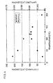
- the magnetization (magnitude) of the magnetic mask layer 3 made of Nd ⁇ Fe is examined by means of VSM (Vibrating Sample Magnetometer), the results of which are set forth in Figure 3 with the measuring results of the magnetization of the recording layer 4 made of Tb ⁇ Fe ⁇ Co.
- Figure 3 reveals that the magnetization of the magnetic mask layer 3 made of Nd ⁇ Fe is reduced to 0 (zero) at 130°C, and becomes larger than that of the recording layer 4 at or below 120°C which is T trans. of the reproducing layer 1.
- the magnetic mask layer 3 is made of alloy of light rare earth metal and 3d transition metal
- the recording layer 4 is made of alloy of heavy rare earth metal and 3d transition metals. More specifically, because light rare. earth metal and 3d transition metal are coupled to each other in parallel, total magnetization of the alloy is a sum of each magnetization. On the contrary, because heavy rare earth metal and 3d transition metal are coupled to each other in anti-parallel, total magnetization of the alloy is an absolute value of a difference among each magnetization. Therefore, the magnetic mask layer 3 made of light rare earth metal and 3d transition metal has larger magnetization than that of the recording layer 4 made of heavy rare earth metal and transition metals.
- the recording bits surrounding the target recording bit in the recording layer 4 are masked satisfactorily by the magnetic mask layer 3 which shows magnetism larger than that of the recording layer 4 and functions effectively (satisfactory masking effect is obtained). Consequently, the CNR can be improved by the above-described arrangement.
- T m at which the magnetization is reduced to 0 (zero) is limited to a range between 100°C arid 250°C both inclusive due to the characteristics of the recording layer 4 and reproducing layer 1. If T m is below 100°C, the characteristics of the recording layer 4 are deteriorated. On the other hand, if T m exceeds 250°C, too much load is applied to the laser, particularly during the recording. For this reason, the Curie temperature of the recording layer 4 is practically set to up to 250°C.
- composition with which the magnetization is reduced to 0 (zero) in a range between 100°C and 250°C both inclusive is examined by means of XRF (X-ray fluoroscopy) analysis, the results of which are set forth in Table 1 below.
- Table 1 reveals that, assume that the composition of Nd ⁇ Fe is indicated as Nd x Fe 100-x , then the suitable composition is in a range 6.0 ⁇ x ⁇ 10.5 (at %, an element ratio in the alloy).
- the characteristics of the reproducing layer 1 and recording layer 4 can be designed in accordance with the characteristics of the magnetic layer 3, and by designing the composition of the magnetic mask layer 3 within the above-specified range, a satisfactory masking effect can be obtained.
- the magneto-optical disk of the preferred embodiment is arranged in the same manner as the counterpart of the comparative example except that the composition of the magnetic mask layer 3 is changed to Nd ⁇ Fe ⁇ Ni.
- the magneto-optical disk of the preferred embodiment is manufactured in the same manner as the counterpart of the comparative example except for the forming step of the magnetic mask layer 3. More specifically, the sputtering apparatus is evacuated until the internal pressure reaches 1 ⁇ 10 -6 Torr (approx. 1.33 ⁇ 10 -4 Pa). Then, Ar gas is supplied and power is supplied to the Fe target, Nd target, and Ni target under a sputtering pressure of 5 ⁇ 10 -3 Torr (approx. 0.665 Pa), whereby a layer made of Nd ⁇ Fe ⁇ Ni is formed.
- the composition of the magnetic mask layer 3 thus formed is Nd 7-5 (Fe 5 Ni 95 ) 92-5 , and the magnetization thereof is reduced to 0 (zero) at 130°C.
- the CNR of the medium of Example 2 is measured under the reproducing conditions: a 680 nm wavelength laser and a 0.55 NA lens at a linear velocity of 2.5 m/sec. with a bit length of 0.4 ⁇ m. Then, it is revealed that CNR is improved by 1 dB compared with the arrangement of Comparative Example 1 above.
- the optimal composition of the magnetic mask layer 3 made of Nd ⁇ Fe ⁇ Ni is examined.
- the magnetic mask layer 3 only has to suppress the leaking of the magnetization of the recording layer 4 to the reproducing layer 1.
- a temperature at which the magnetization is reduced to 0 (zero) is limited to a range between 100°C and 250°C both inclusive due to the characteristics of the recording layer 4 and reproducing layer 1.
- the composition with which the magnetization is reduced to 0 (zero) in a range between 100°C and 250°C both inclusive is examined by means of XRF analysis, the results of which are set forth in Table 2 below.
- the characteristics of the reproducing layer 1 and recording layer 4 can be designed in accordance with the characteristics of the magnetic layer 3, and by designing the composition of the magnetic mask layer 3 within the above-specified ranges, a satisfactory masking effect can be obtained.
- a temperature (T m ), at which the magnetization of the magnetic mask layer is reduced to 0 (zero), may be set below T trans. of the reproducing layer. In this case, if such a temperature is far below T trans , the magnetization is leaked from more than one recording bit.
- T trans. - 80(°C) ⁇ T n and more preferably T trans. -60(°C) ⁇ T m is satisfied.
- the arrangement of the magneto-optical disk is not limited to those described as preferred embodiment and an auxiliary reproducing layer or an auxiliary recording layer may be additionally provided, or the magnetic mask layer and recording layer may be magneto-statically coupled to each other.
- the non-magnetic intermediate layer of a single-layer structure provided between the reproducing layer and magnetic mask layer may be replaced with any other layer which can prevent exchanged coupling between the reproducing layer and magnetic mask laver.
- the magneto-optical recording medium is not limited to the magneto-optical disk.
- the magneto-optical recording medium may be a magneto-optical tape, a magneto-optical card, etc.
Claims (5)
- Support d'enregistrement magnéto-optique comportant :caractérisé en ce queune couche de reproduction (1) dont la direction d'aimantation se situe dans le plan à la température ambiante et passe à la direction perpendiculaire à ou au-dessus d'une température de transition prédéterminée Ttrans ;une couche d'enregistrement (4) dont la direction d'aimantation est perpendiculaire dans une gamme comprise entre la température ambiante et sa température de Curie, gamme dans laquelle ladite couche d'enregistrement est couplée magnéto-statiquement à: ladite couche de reproduction ; etune couche de masquage magnétique (3) qui est prévue entre ladite couche de reproduction (1) et ladite couche d'enregistrement (4), une couche intermédiaire (2) étant prévue du côté de ladite couche de reproduction, et dont la direction d'aimantation est dans le plan à la température ambiante ;
ladite couche de masquage magnétique est réalisée en Nd·Fe·Ni. - Support d'enregistrement magnéto-optique selon la revendication 1, dans lequel l'aimantation de ladite couche de masquage magnétique est réduite à 0 (zéro) à ou au-dessus d'une température prédéterminée Tm qui est égale ou supérieure à ladite température de transition prédéterminée Ttrans.
- Support d'enregistrement magnéto-optique selon la revendication 1, dans lequel la composition dudit alliage Nd·Fe·Ni de ladite couche de masquage magnétique est exprimée par Ndx (FeyNl100-y)100-x, et dans lequel x se situe dans une gamme de 5.0≤x≤10,5 (en %) et y se situe dans une gamme de 5,0≤y≤70,0 (en %).
- Support d'enregistrement magnéto-optique selon la revendication 2, dans lequel ladite température prédéterminée Tm se situe dans une gamme comprise entre 100°C et 250°C, Ces deux valeurs étant comprises.
- Support d'enregistrement magnéto-optique selon la revendication 1, dans lequel l'aimantation de ladite couche de masquage magnétique est réduite à o (zéro) à ou au-dessus de ladite température prédéterminée Tm qui satisfait ladite température de transition prédéterminée Ttrans-80(°C)≤ ladite température prédéterminée Tm.
Applications Claiming Priority (2)
| Application Number | Priority Date | Filing Date | Title |
|---|---|---|---|
| JP33864898A JP3519295B2 (ja) | 1998-11-30 | 1998-11-30 | 光磁気記録媒体 |
| JP33864898 | 1998-11-30 |
Publications (3)
| Publication Number | Publication Date |
|---|---|
| EP1006520A2 EP1006520A2 (fr) | 2000-06-07 |
| EP1006520A3 EP1006520A3 (fr) | 2001-11-28 |
| EP1006520B1 true EP1006520B1 (fr) | 2003-09-17 |
Family
ID=18320160
Family Applications (1)
| Application Number | Title | Priority Date | Filing Date |
|---|---|---|---|
| EP99123588A Expired - Lifetime EP1006520B1 (fr) | 1998-11-30 | 1999-11-26 | Milieu d'enregistrement magnéto-optique |
Country Status (4)
| Country | Link |
|---|---|
| US (1) | US6477120B1 (fr) |
| EP (1) | EP1006520B1 (fr) |
| JP (1) | JP3519295B2 (fr) |
| DE (1) | DE69911353T2 (fr) |
Families Citing this family (1)
| Publication number | Priority date | Publication date | Assignee | Title |
|---|---|---|---|---|
| KR100499136B1 (ko) * | 2002-12-14 | 2005-07-04 | 삼성전자주식회사 | 전자 스핀의존 산란을 이용한 자성매체 및 자성매체정보재생장치 및 재생방법 |
Family Cites Families (13)
| Publication number | Priority date | Publication date | Assignee | Title |
|---|---|---|---|---|
| JP3072812B2 (ja) * | 1993-04-08 | 2000-08-07 | キヤノン株式会社 | 光磁気記録媒体及び該媒体の情報再生方法 |
| JPH07110971A (ja) * | 1993-10-13 | 1995-04-25 | Pioneer Electron Corp | 光磁気記録媒体、光磁気記録媒体記録装置及び光磁気記録媒体再生装置 |
| JP3088619B2 (ja) * | 1994-01-17 | 2000-09-18 | 富士通株式会社 | 光磁気記録媒体及び該媒体に記録された情報の再生方法 |
| JP3380621B2 (ja) | 1994-06-24 | 2003-02-24 | 日立マクセル株式会社 | 光磁気記録媒体の再生方法、光磁気記録媒体およびそれを用いた光磁気記録再生装置 |
| JP3781823B2 (ja) * | 1996-05-27 | 2006-05-31 | シャープ株式会社 | 光磁気記録媒体及びその再生方法 |
| JP3333389B2 (ja) * | 1996-07-05 | 2002-10-15 | 株式会社日立製作所 | 光磁気情報記憶媒体およびその再生方法 |
| JP3400251B2 (ja) * | 1996-07-30 | 2003-04-28 | シャープ株式会社 | 光磁気記録媒体の再生方法及び光磁気記録媒体 |
| US5903526A (en) * | 1996-09-20 | 1999-05-11 | Victor Company Of Japan, Ltd. | Magneto-optical recording medium having multiple magnetic layers |
| US6147939A (en) * | 1997-03-06 | 2000-11-14 | Sharp Kabushiki Kaisha | Magneto-optical recording medium having intermediate layer of in-plane magnetization |
| JP4027490B2 (ja) | 1997-03-06 | 2007-12-26 | シャープ株式会社 | 光磁気記録媒体及びその再生方法 |
| JP3349403B2 (ja) * | 1997-07-31 | 2002-11-25 | シャープ株式会社 | 光磁気記録媒体 |
| JPH11162029A (ja) | 1997-12-01 | 1999-06-18 | Kyocera Corp | 光磁気記録媒体 |
| JPH11191244A (ja) | 1997-12-26 | 1999-07-13 | Sharp Corp | 光磁気記録媒体及びその再生方法 |
-
1998
- 1998-11-30 JP JP33864898A patent/JP3519295B2/ja not_active Expired - Fee Related
-
1999
- 1999-11-26 DE DE69911353T patent/DE69911353T2/de not_active Expired - Lifetime
- 1999-11-26 EP EP99123588A patent/EP1006520B1/fr not_active Expired - Lifetime
- 1999-11-30 US US09/451,260 patent/US6477120B1/en not_active Expired - Lifetime
Also Published As
| Publication number | Publication date |
|---|---|
| JP2000163816A (ja) | 2000-06-16 |
| EP1006520A2 (fr) | 2000-06-07 |
| JP3519295B2 (ja) | 2004-04-12 |
| DE69911353D1 (de) | 2003-10-23 |
| EP1006520A3 (fr) | 2001-11-28 |
| DE69911353T2 (de) | 2004-07-15 |
| US6477120B1 (en) | 2002-11-05 |
Similar Documents
| Publication | Publication Date | Title |
|---|---|---|
| US5939187A (en) | Magneto-optical recording medium | |
| US6147939A (en) | Magneto-optical recording medium having intermediate layer of in-plane magnetization | |
| US5665468A (en) | Magneto-optical recording medium | |
| US6388956B1 (en) | Magneto-optical storage media | |
| US5596555A (en) | Magnetooptical recording medium having magnetic layers that satisfy predetermined coercive force relationships, and recording/reproduction method for the medium | |
| US6356516B2 (en) | Magneto-optical recording medium and reproducing method for information recorded on the medium | |
| US6463015B1 (en) | Method of reproducing information on a magneto-optical recording medium for achieving super resolution reproduction of high resolution recorded information | |
| US6504797B1 (en) | Magneto-optical recording medium having multiple magnetic layers and reproducing method thereof | |
| EP1006520B1 (fr) | Milieu d'enregistrement magnéto-optique | |
| US5547751A (en) | Magneto-optical recording medium and method of manufacturing the same | |
| JP2000285534A (ja) | 光磁気記録媒体及びその再生方法 | |
| JP3349403B2 (ja) | 光磁気記録媒体 | |
| EP0385786A1 (fr) | Milieu d'enregistrement magnéto-optique | |
| EP0803870B1 (fr) | Support d'enregistrement magnétooptique | |
| JPH11134730A (ja) | 光磁気記録媒体及びその再生方法 | |
| US6010780A (en) | Magneto-optical memory medium | |
| US6534162B1 (en) | Magneto-optical recording medium | |
| JPH08124229A (ja) | 光磁気記録媒体 | |
| JP2000222787A (ja) | 光磁気記録媒体 | |
| JP3418088B2 (ja) | 光磁気記録媒体及び光磁気記録媒体の再生方法 | |
| EP1170742A2 (fr) | Support d'enregistrement magnéto-optique et procédé pour sa fabrication | |
| JP2001209983A (ja) | 光磁気記録媒体 | |
| JP2007188637A (ja) | 光磁気記録媒体及びその再生方法 | |
| JP2007188636A (ja) | 光磁気記録媒体及びその再生方法 |
Legal Events
| Date | Code | Title | Description |
|---|---|---|---|
| PUAI | Public reference made under article 153(3) epc to a published international application that has entered the european phase |
Free format text: ORIGINAL CODE: 0009012 |
|
| AK | Designated contracting states |
Kind code of ref document: A2 Designated state(s): AT BE CH CY DE DK ES FI FR GB GR IE IT LI LU MC NL PT SE Kind code of ref document: A2 Designated state(s): DE FR GB |
|
| AX | Request for extension of the european patent |
Free format text: AL;LT;LV;MK;RO;SI |
|
| RIC1 | Information provided on ipc code assigned before grant |
Free format text: 7G 11B 11/105 A |
|
| PUAL | Search report despatched |
Free format text: ORIGINAL CODE: 0009013 |
|
| AK | Designated contracting states |
Kind code of ref document: A3 Designated state(s): AT BE CH CY DE DK ES FI FR GB GR IE IT LI LU MC NL PT SE |
|
| AX | Request for extension of the european patent |
Free format text: AL;LT;LV;MK;RO;SI |
|
| 17P | Request for examination filed |
Effective date: 20020218 |
|
| 17Q | First examination report despatched |
Effective date: 20020606 |
|
| AKX | Designation fees paid |
Free format text: DE FR GB |
|
| GRAH | Despatch of communication of intention to grant a patent |
Free format text: ORIGINAL CODE: EPIDOS IGRA |
|
| GRAS | Grant fee paid |
Free format text: ORIGINAL CODE: EPIDOSNIGR3 |
|
| GRAA | (expected) grant |
Free format text: ORIGINAL CODE: 0009210 |
|
| AK | Designated contracting states |
Kind code of ref document: B1 Designated state(s): DE FR GB |
|
| REG | Reference to a national code |
Ref country code: GB Ref legal event code: FG4D |
|
| REF | Corresponds to: |
Ref document number: 69911353 Country of ref document: DE Date of ref document: 20031023 Kind code of ref document: P |
|
| ET | Fr: translation filed | ||
| PLBE | No opposition filed within time limit |
Free format text: ORIGINAL CODE: 0009261 |
|
| STAA | Information on the status of an ep patent application or granted ep patent |
Free format text: STATUS: NO OPPOSITION FILED WITHIN TIME LIMIT |
|
| 26N | No opposition filed |
Effective date: 20040618 |
|
| PGFP | Annual fee paid to national office [announced via postgrant information from national office to epo] |
Ref country code: DE Payment date: 20141119 Year of fee payment: 16 Ref country code: GB Payment date: 20141119 Year of fee payment: 16 Ref country code: FR Payment date: 20141119 Year of fee payment: 16 |
|
| REG | Reference to a national code |
Ref country code: DE Ref legal event code: R119 Ref document number: 69911353 Country of ref document: DE |
|
| GBPC | Gb: european patent ceased through non-payment of renewal fee |
Effective date: 20151126 |
|
| REG | Reference to a national code |
Ref country code: FR Ref legal event code: ST Effective date: 20160729 |
|
| PG25 | Lapsed in a contracting state [announced via postgrant information from national office to epo] |
Ref country code: DE Free format text: LAPSE BECAUSE OF NON-PAYMENT OF DUE FEES Effective date: 20160601 Ref country code: GB Free format text: LAPSE BECAUSE OF NON-PAYMENT OF DUE FEES Effective date: 20151126 |
|
| PG25 | Lapsed in a contracting state [announced via postgrant information from national office to epo] |
Ref country code: FR Free format text: LAPSE BECAUSE OF NON-PAYMENT OF DUE FEES Effective date: 20151130 |