EP1007244B1 - Gleichlauf-trennen von modell und sandballen - Google Patents
Gleichlauf-trennen von modell und sandballen Download PDFInfo
- Publication number
- EP1007244B1 EP1007244B1 EP98948721A EP98948721A EP1007244B1 EP 1007244 B1 EP1007244 B1 EP 1007244B1 EP 98948721 A EP98948721 A EP 98948721A EP 98948721 A EP98948721 A EP 98948721A EP 1007244 B1 EP1007244 B1 EP 1007244B1
- Authority
- EP
- European Patent Office
- Prior art keywords
- stroke
- axes
- model
- individually
- carriage
- Prior art date
- Legal status (The legal status is an assumption and is not a legal conclusion. Google has not performed a legal analysis and makes no representation as to the accuracy of the status listed.)
- Expired - Lifetime
Links
- 239000004576 sand Substances 0.000 title claims abstract description 29
- 238000000926 separation method Methods 0.000 title claims description 21
- 230000001360 synchronised effect Effects 0.000 title claims description 5
- 238000000465 moulding Methods 0.000 claims abstract description 44
- 238000000034 method Methods 0.000 claims abstract description 20
- 230000001105 regulatory effect Effects 0.000 claims abstract description 13
- 230000008569 process Effects 0.000 claims description 18
- 239000000463 material Substances 0.000 claims description 10
- 230000033228 biological regulation Effects 0.000 claims description 9
- 238000003825 pressing Methods 0.000 claims description 6
- 230000008859 change Effects 0.000 claims description 5
- 230000000694 effects Effects 0.000 abstract description 3
- 238000006073 displacement reaction Methods 0.000 description 8
- 230000006835 compression Effects 0.000 description 7
- 238000007906 compression Methods 0.000 description 7
- 238000009423 ventilation Methods 0.000 description 5
- 238000010586 diagram Methods 0.000 description 4
- 238000005520 cutting process Methods 0.000 description 3
- 238000005259 measurement Methods 0.000 description 3
- 230000004308 accommodation Effects 0.000 description 1
- 230000008901 benefit Effects 0.000 description 1
- 239000000969 carrier Substances 0.000 description 1
- 238000011109 contamination Methods 0.000 description 1
- 230000001276 controlling effect Effects 0.000 description 1
- 238000006880 cross-coupling reaction Methods 0.000 description 1
- 230000007423 decrease Effects 0.000 description 1
- 238000009795 derivation Methods 0.000 description 1
- 239000012535 impurity Substances 0.000 description 1
- 230000007257 malfunction Effects 0.000 description 1
- 239000012778 molding material Substances 0.000 description 1
- 239000003110 molding sand Substances 0.000 description 1
- 230000009467 reduction Effects 0.000 description 1
- 230000000630 rising effect Effects 0.000 description 1
- 230000002123 temporal effect Effects 0.000 description 1
- 230000007704 transition Effects 0.000 description 1
- 230000001960 triggered effect Effects 0.000 description 1
Images



Classifications
-
- B—PERFORMING OPERATIONS; TRANSPORTING
- B22—CASTING; POWDER METALLURGY
- B22C—FOUNDRY MOULDING
- B22C11/00—Moulding machines characterised by the relative arrangement of the parts of same
- B22C11/02—Machines in which the moulds are moved during a cycle of successive operations
- B22C11/08—Machines in which the moulds are moved during a cycle of successive operations by non-rotary conveying means, e.g. by travelling platforms
-
- B—PERFORMING OPERATIONS; TRANSPORTING
- B22—CASTING; POWDER METALLURGY
- B22C—FOUNDRY MOULDING
- B22C17/00—Moulding machines characterised by the mechanism for separating the pattern from the mould or for turning over the flask or the pattern plate
Definitions
- the invention relates to an apparatus and a method for separating a model and the bale of sand molded in a mold using the model, in the model and shape - with horizontal alignment of their horizontal dividing surfaces - in the direction a normal to these dividing surfaces can be moved relatively apart.
- a mechanical synchronizing device is provided, which is arranged below the model carrier. This requires a spacious basement room under the machine.
- the mechanically controlled synchronization takes place via a centrally guided common yoke, which lifts the four guide rods that serve to lift off evenly.
- One problem is that the yoke has to be freed or uncoupled from these guide rods, for example during the pressing process. In practice, it can be seen that the resulting impurities can have a negative impact on synchronism.
- the CH-A-622.724 also shows a lifting machine (see there the summary and page 2, left column, last third), which works with a common valve for two lifting cylinders (see there the pressure medium cylinders 62 and 148 and that common valve 152 in the figure 2) there.
- a lifting machine see there the summary and page 2, left column, last third
- US-A-4,100,961 which describes a plurality of mutually parallel lifting axes in FIGS. 2 and 3 there (reference numbers 19).
- This machine produces cores (cf. column 1, lines 1 to 13) and therefore does not represent a molding machine with which a model and a mold material molded using the model and a molding box are separated.
- DE-B-39 20 889 (Rienkel-Wagner) also shows a lift -off in FIG. 2 there and in column 2 from line 59 to column 3, line 7.
- pistons which are acted upon separately and are arranged coaxially. which achieve the separation of molded box and model via a support system, but again with a cellar room and a mechanical synchronizing device through rigid mechanical connections.
- the regulation (claim 10) is regulation of the lifting height (displacement regulation), preferably via a PID controller, which is used for ramp responses (steadily increasing Lifting heights) does not produce a dynamic control error (synchronism error).
- a particular advantage is that for the individually driven and regulated Axes only require a floor-level foundation and a generously designed one Basement space under the machine is unnecessary. It has also been shown that Contamination and its negative influence on synchronism are reliable can be avoided.
- the arrangement has high accuracy because of the lifting axes, which are made individually driven vertical drives, lifting cylinders, spindle drives, servo drives or other electric drives with spindle rod can be designed with their lower end area are fixed and only upwards in the vertical direction are extendable, which in the following with the lifting height y (t) as the instantaneous value of the Lifting height over time is called.
- the invention goes the way of several individual linear actuators use and at the same time let them attack at the edges to either the Form box itself with the sand bales or the model opposite the form box relatively separate with the bale of sand.
- the separating movement runs regularly in the axis that is vertical to the normal Box transport displacement direction and the individually driven lifting axes are aligned parallel to this vertical (normal).
- the edge attack ensures an exact introduction of the force and avoids mechanical imbalances that in the central introduction of forces and the distribution of the force on the edges created by a mechanical, transverse yoke. So there are none mechanical drive means below the fixed cylinders or other Drives of the individually driven lifting axes required (claim 3), rather only move these lifting axes vertically in and out and are at the bottom Fixed end.
- the fixed arrangement can be on a movable carriage be provided, which means not only moving the unit from the molding box, Filling frame and model as well as model carrier allowed, but also common Support device is that is precisely aligned with the vertical (Claim 4).
- this carriage can with a horizontally oriented cylinder rod, which is below the Wagens attacks (claim 9). It will be this tie rod that pulls the cart out of the Takes out the main box conveying direction and moves to the parallel station, very much kept short. It attacks at the outer, lower end of the car without it from deeper mechanical devices is hindered, according to the invention are no longer required.
- the regulation of the individual drives can have several configurations Experienced.
- a particularly gentle separation of the molded material bale and the model is then possible possible if the separation speed is strong at the beginning of the separation process is reduced to allow ventilation (claim 19).
- At the same time is one low speed at the starting point of the mechanical start of the separation also advantageous because minor vibrations are caused, which is what the advantageous results of the invention result with a low Speed, a so-called creep speed at the moment and shortly before Disconnect works while after that after the critical time of disconnection and ventilation is over, the speed of separation can be increased again.
- the separation no longer has an immediate effect on the surface of the Bales of sand, but only serves the greater spacing of bales of sand and Model.
- the manipulated variables are the signals that are the output variables of the controller and that the hydraulic or electrical actuators for controlling the axis are supplied. Too large strokes are a sign that high forces are acting on the individual Stroke axes try to adjust individually, but at the same time a signal for it may be that an error that leads to a strong asymmetry or that of a such strong asymmetry, can be recognized. To capture this strongly differing strokes, a second tolerance band can be used. Will be one Tolerance band exceeded, either the error can only be registered or but the lifting speed of all axes are immediately reduced to one To give intervention.
- This averager not only monitors one axis, but all provided axes and forms a total mean of all actual height values, which are measured individually on each axis. From these total elevation values an average is formed, which is then used as an additional setpoint for each controller can be switched on, so that there is an additional equalization.
- This additional connection works in such a way that those controllers that are stronger in one or are deflected in another direction, either accelerated or braked, so that the lifting process is evened out.
- the additional control loop can be specifically provided with integral parts, since this integral part with a very sluggish controlled system little disturbing and yet for practically preserved least possible error.
- the additional controllers then work like Additional connections in the sense of a feedforward control, because the others also Controllers of the lifting axes are also available, but then preferably with one P control behavior.
- FIG. 2 shows a press station 1 with a customary multi-punch press head 1a and a customary press table 3, which can be raised in the direction of the press head 1a by means of a conventional device 4.
- a sliding device 5 for mold boxes 7 with model carrier 8 and model 8a is arranged between the pressing station 1 and a station 2 which is also used for sand filling.
- the normal corridor level is indicated by 12.
- the model carrier is designated 8 with model 8a.
- This lifting machine has a filling frame 6 below a sand bunker 10, and four guide rods 13, on which the for lifting the sand bale containing molded box 7 serving elements are arranged.
- the Guide rods 13 are raised together by a yoke 9, which with the help a lifting device 11 arranged in a basement 14 raised and can be lowered.
- the separating device 2 is in turn arranged next to a press station 1.
- the same parts are labeled in the same way as in FIG . 2 .
- the normal to the dividing surfaces of the mold and the ball of sand is designated by 20.
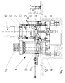
- four individually driven and controlled hydraulic lifting cylinders 15, 16 are provided for separation in the arrangement according to FIG . Together, these are supported a little above the foundation, which lies on the corridor level 12. A large basement room is therefore not required. A little above the foundation, the carriage 30 defining the support is laterally displaceable.
- the carriage 30 can be shifted from left to right (and vice versa) in FIG. 1 , via the shifting device 5.
- This direction ⁇ A is transverse to the transport direction K of the molded boxes, which is oriented perpendicular to the paper plane, cf. also Figure 4 .
- hydraulic lifting cylinders 15, 16 electrically operated drives can also be provided. They are also displacement-controlled in their lifting height y, preferably via individual sensors on each “axis”, which provide the actual values y (t) for the displacement control of FIG. 5 . Cross coupling from one axis to the other is avoided; each axis regulates to its own setpoints - which are given in the same way - and regulates its own disturbance variables that occur individually, cf. see Figure 6.
- the arrangement 5 previously described as being displaceable in the direction ⁇ A will be explained in more detail in FIG .
- It consists of a horizontally lying cylinder, the cylinder area of which comes to lie below the compression station 1 and the pull / push rod 5z when the carriage 30 is moved over below the filling station 2.
- This rod 5z is arranged with its front end at the outer end region on the underside of the carriage 30 and can, when the cylinder 5 is triggered, pull the carriage 30 together with the unit consisting of model carrier 8, molding box 7, filling frame 6 into the compression station 1 and after that Compress back into the main box conveying direction K, which can be seen in Figure 4 .
- the cylinder 5 does not protrude much laterally next to the compression station 1, which is caused by the fact that below the support rail 31, on which the carriage 30 can be moved by means of rollers 32a, 32b, no further mechanical Elements are provided which have to perform strokes in the filling station in the vertical direction, rather the area between the lower edge of the running rail 31 and the foundation 12 is practically free here.
- the direction in which the displacement device 5 performs the movement is designated ⁇ A, it is perpendicular to the box conveying direction K according to FIG. 4.
- FIG. 3f shows the same device that was explained in FIG. 1, only additional support feet 33 are arranged on the foundation 12, which support the guide rail 31 below the filling station 2, on which the carriage 30 with its pairs of rollers 32a, 32b is laterally displaceable, in direction A.
- the conveying direction K of the boxes is perpendicular to the plane of the paper.
- the compressed molding box of FIG. 3a is pushed out (to the front), while an uncompressed, yet empty molding box in FIG. 3b moves into the filling station, held by roller conveyor sections 41, which are supported on downwardly projecting support arms 40 at the upper region 16a of the respective lifting axes 16 are arranged, cf. see FIG. 1 in detail.
- FIG. 3b the compression station 1 with its multi-punch press head 1a is in the basic position.
- the lifting cylinder 4 is also retracted.
- the retracted (still empty) molding box 7 and then the filling frame 6 are placed on the model plate carrier 8 with the lifting axes 15, 16 in order to enclose the model 8a.
- FIG. 3c is reached, in which molding material is additionally filled into the unit consisting of molding box, filling frame and model.
- the pre-selected amount of sand can be specified using a trigger belt conveyor.
- the amount of sand can be set depending on the model, e.g. B. by entering the number of revolutions of a pulley of the trigger belt conveyor, which are specified in the associated control.
- the compression station is still in the basic position in FIG. 3c.
- the unit filled with sand on vehicle 30 is moved over to the compression station, in direction A.
- FIG. 3d the press cylinders 1a compress the molding sand above the model after the unit has been lifted off the carriage by means of the lifting cylinder 4 and pressed against the press head from below.
- the lifting cylinder 4 lowers the unit again - now in the compressed state - onto the carriage 30, which travels in the direction -A into the filling station, which achieves the state of FIG. 3e .
- the plungers 16 which have been retracted up to that point now begin to separate the compressed sand bale 7a from the model 8a.
- the lifting axes 15, 16 are electronically controlled with the highest accuracy and first of all lift the filling frame, which can be seen from the transition from FIG. 3e to FIG. 3f .
- the downward-reaching carrier 41 is so long that the filling frame 6 is first raised at the upper end 16a of the lifting axis, and no mechanical vibrations of the model are associated with it. Only after a short stroke, in which the molding box 7 has not yet been gripped, do the supports 40 with their lower end, a roller section, engage the corresponding counter sections of the molding box 7 and raise it mechanically. This lifting process will become clearer later, with a view to FIG. 6, in which the three time periods of the separating stroke of the filling frame, the creep speed and the remaining stroke can be explained in more detail.
- the free lifting of the filling frame is the starting point and at the beginning of the lifting of the molding box, a low speed is set in order to take the molding box softly off the rollers and to give the mold time for the separation process for ventilation.
- the lifting axes then continue to lift, this time faster, until the molding box has reached the height of the runways which are in the main box transport direction K of FIG. 4.
- FIG. 4 illustrates the retracted retraction of a model or the change of a model for an alternate impression of the upper box and lower box.
- the arrangement of the four individually regulated lifting axes 15, 16 in the corner regions of the molding box 7 can be seen in FIG. 4 when it is retracted in the filling station.
- the compression station 1 is offset parallel to the main box transport direction K and the carriage 30 is moved into the filling station 2 in the position shown in FIG.
- 30 arrangements are provided transversely to the direction of displacement A of the first carriage, which enable the retraction of a model for the upper box or a model for the lower box or other models.
- roller conveyors (sections thereof) are each mounted on further carriages 35 above and below the filling station 2 shown in FIG. These carriages can be moved out (to the side) for changing the model or the model plate carrier, so that the model plate carriers are accessible as well as possible in the areas 36a, 36b. After the change, the car is transported back to the shuttle position.
- An additional (second) thrust cylinder 5a controls the movement of the second carriage 35, which first drives the model onto the first carriage 30 via corresponding rollers and track sections, where it comes into connection with the molding box 7.
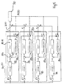
- FIG. 6 This course of the measured values and setpoints is to be explained in connection with FIG. 5, which shows the control with which the four lifting axes of FIG. 1 are individually controlled.
- the starting point for the control of FIG. 5 is the jointly predetermined setpoint y S (t), which is jointly predetermined for all four axes.
- Each controller has a set-actual value comparison, which subtracts the actual lift value y (t) of the respective individual axis from the setpoint y s (t) and the difference as a control difference a respective individual controllers 81, 82, 83, 84 dictates.
- This controller controls the drive for the respective axis, referred to in the figure 5 with axis 1, axis 2, axis 3 and axis 4, and results in the control equivalent circuit diagram an actual value of the lifting height y (t), each individually for each Depending on the disturbance variables, the stroke axis results in individual effects on each axis.
- the additional controllers 81a, 82a, 83a, 84a which have already been drawn in in FIG. 5 and which are synchronous controllers for the respective axis and are fed by an averager 90 will be explained later.
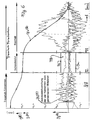
- the starting point was the specification of a common setpoint, which appears as the course of the lifting height over time in FIG. 6 .
- the gradient of the filling frame 6 is separated from the molding box 7, initially rising slightly and then steeper up to the point in time T0.
- the respective synchronization deviations for the four axes used are shown with y f (t) in FIG. They are not identical, but run into a jointly predetermined window between the limit values y o and y u , which is important for creep speed, in which the mold box 7 with the bale of sand 7a is lifted off the model 8a.
- the start of the lift-off, the time T0, at which the lowest possible speed is specified by the setpoint y s (t) is relevant for this, that is, sufficient time for ventilation and little susceptibility to faults.
- the tolerance band TB delimited by the limit values y o and y u is set to ⁇ 0.05 mm in the example shown, but in fact the synchronism fluctuations are even smaller, as can be seen from the measurement in the tolerance band TB.
- FIG. 6 shows a time span of approximately 2.4 seconds for a complete disconnection, the course of the setpoint value for the lifting height y s (t) illustrating a larger path difference than the greatly enlarged scale drawn in between -0.1 and +0. 5 mm to show the synchronism deviations y f (t).
- controller 5 uses proportional controllers for the controllers 81, 82, 83, 84 in order to regulate the controlled systems of the axes, which can be represented with a PT2 component for the valve with hydraulic control and an IT2 component for the cylinder ,
- the additionally shown synchronous controllers 81a can be P controllers, but they preferably have an integral component switched on in order to switch off control errors even if ramps are specified by the height setpoint y s (t).
- the mean value generator 90 detects the sum of all stroke values y (t) of all axes and calculates an average M (t) for respective comparator points 81c, which individually subtract the individual actual value y (t) of each axis and the Specify additional controllers 81a, 82a, 83a, 84a.
- This as a proportional or PI controller configured synchronous controller switches a pilot control to a summing point 81b to influence the controlled system 15, 16 of the respective axis.
- All used lifting axes should preferably have the same behavior and therefore also have the same rule structure.
- An adapted position measuring system can be used as a measuring device for the measuring height, adapted to the type of the respective axis, such as a dipstick for a lifting cylinder or a rotary encoder for driven spindle rods.
- the setpoints, actual values and manipulated variables can be monitored at any time.
- the manipulated variable of each controller of each axis can be monitored for a tolerance band with a maximum value, so that the manipulated variables are not too large during the separation process. If it is determined that one of the manipulated variables lies outside the previously defined limit value or leaves the specified tolerance band, an error can be concluded.
- the associated cylinder is then loaded with either too large or too small a force.
- An emerging malfunction can be compensated preventively by e.g. B. the slope of the setpoint curve y s (t) is reduced in order to reduce the path difference and to bring the torn manipulated variable back into the tolerance band.
- FIG. 6 shows the high accuracy in the time range T0 to T1, which corresponds to creep speed.
- the approach to time T0 can also be influenced by a controller that operates in such a way that the setpoint specification of the stroke is reduced until the shown synchronization deviations y f (t) lie within the tolerance band TB when time T0 is reached.
Landscapes
- Engineering & Computer Science (AREA)
- Mechanical Engineering (AREA)
- Casting Devices For Molds (AREA)
- Separation Of Solids By Using Liquids Or Pneumatic Power (AREA)
- Underground Or Underwater Handling Of Building Materials (AREA)
- Investigation Of Foundation Soil And Reinforcement Of Foundation Soil By Compacting Or Drainage (AREA)
- Molds, Cores, And Manufacturing Methods Thereof (AREA)
- Farming Of Fish And Shellfish (AREA)
- Analysing Materials By The Use Of Radiation (AREA)
Applications Claiming Priority (3)
| Application Number | Priority Date | Filing Date | Title |
|---|---|---|---|
| DE19733703A DE19733703B4 (de) | 1997-08-04 | 1997-08-04 | Gleichlauf-Trennen von Modell und Sandballen |
| DE19733703 | 1997-08-04 | ||
| PCT/DE1998/002237 WO1999006165A2 (de) | 1997-08-04 | 1998-08-04 | Gleichlauf-trennen von modell und sandballen |
Publications (2)
| Publication Number | Publication Date |
|---|---|
| EP1007244A2 EP1007244A2 (de) | 2000-06-14 |
| EP1007244B1 true EP1007244B1 (de) | 2004-05-06 |
Family
ID=7837963
Family Applications (1)
| Application Number | Title | Priority Date | Filing Date |
|---|---|---|---|
| EP98948721A Expired - Lifetime EP1007244B1 (de) | 1997-08-04 | 1998-08-04 | Gleichlauf-trennen von modell und sandballen |
Country Status (8)
| Country | Link |
|---|---|
| EP (1) | EP1007244B1 (pt) |
| JP (1) | JP2001512048A (pt) |
| AT (1) | ATE265905T1 (pt) |
| BR (1) | BR9811077A (pt) |
| DE (3) | DE19733703B4 (pt) |
| DK (1) | DK1007244T3 (pt) |
| ES (1) | ES2219910T3 (pt) |
| WO (1) | WO1999006165A2 (pt) |
Cited By (1)
| Publication number | Priority date | Publication date | Assignee | Title |
|---|---|---|---|---|
| CN104014749A (zh) * | 2014-05-16 | 2014-09-03 | 铜陵和武机械制造有限责任公司 | 一种自动翻转砂模 |
Families Citing this family (2)
| Publication number | Priority date | Publication date | Assignee | Title |
|---|---|---|---|---|
| WO2023127226A1 (ja) * | 2021-12-27 | 2023-07-06 | メタルエンジニアリング株式会社 | 鋳型造型装置および鋳型造型方法 |
| CN121443408A (zh) * | 2024-01-30 | 2026-01-30 | 金属机械股份有限公司 | 浇铸完毕铸模拔出装置以及浇铸完毕铸模拔出方法 |
Family Cites Families (5)
| Publication number | Priority date | Publication date | Assignee | Title |
|---|---|---|---|---|
| DE1210517B (de) * | 1963-01-30 | 1966-02-10 | Badische Maschinenfabrik A G S | Verfahren und Vorrichtung zum Loesen einer Giessereiform mit Ballen aus dem Ballenmodell |
| US3776300A (en) * | 1969-05-15 | 1973-12-04 | W Fismer | Apparatus for lifting flasks, molds and patterns |
| US4100961A (en) * | 1976-11-18 | 1978-07-18 | Acme-Cleveland Corporation | Foundry molding machine |
| CH622724A5 (pt) * | 1977-07-22 | 1981-04-30 | Fischer Ag Georg | |
| DE3920889C2 (de) * | 1989-06-26 | 1997-05-07 | Kuenkel Wagner Prozesstechnolo | Formmaschine |
-
1997
- 1997-08-04 DE DE19733703A patent/DE19733703B4/de not_active Expired - Lifetime
-
1998
- 1998-08-04 DK DK98948721T patent/DK1007244T3/da active
- 1998-08-04 DE DE19882523T patent/DE19882523B4/de not_active Expired - Lifetime
- 1998-08-04 ES ES98948721T patent/ES2219910T3/es not_active Expired - Lifetime
- 1998-08-04 DE DE59811340T patent/DE59811340D1/de not_active Expired - Lifetime
- 1998-08-04 JP JP2000504965A patent/JP2001512048A/ja active Pending
- 1998-08-04 EP EP98948721A patent/EP1007244B1/de not_active Expired - Lifetime
- 1998-08-04 BR BR9811077-2A patent/BR9811077A/pt not_active IP Right Cessation
- 1998-08-04 AT AT98948721T patent/ATE265905T1/de not_active IP Right Cessation
- 1998-08-04 WO PCT/DE1998/002237 patent/WO1999006165A2/de not_active Ceased
Non-Patent Citations (1)
| Title |
|---|
| Produktblatt "Rüttel-Press-Abhebe-Formmaschine" Typ APM-s/APM-sm der Firma KÜNKEL-WAGNER * |
Cited By (1)
| Publication number | Priority date | Publication date | Assignee | Title |
|---|---|---|---|---|
| CN104014749A (zh) * | 2014-05-16 | 2014-09-03 | 铜陵和武机械制造有限责任公司 | 一种自动翻转砂模 |
Also Published As
| Publication number | Publication date |
|---|---|
| ATE265905T1 (de) | 2004-05-15 |
| JP2001512048A (ja) | 2001-08-21 |
| WO1999006165A3 (de) | 1999-04-08 |
| DE59811340D1 (de) | 2004-06-09 |
| DK1007244T3 (da) | 2004-08-30 |
| ES2219910T3 (es) | 2004-12-01 |
| BR9811077A (pt) | 2000-09-05 |
| DE19882523D2 (de) | 2000-07-06 |
| WO1999006165A2 (de) | 1999-02-11 |
| DE19733703A1 (de) | 1999-02-18 |
| DE19882523B4 (de) | 2008-08-21 |
| DE19733703B4 (de) | 2007-10-25 |
| EP1007244A2 (de) | 2000-06-14 |
Similar Documents
| Publication | Publication Date | Title |
|---|---|---|
| EP2707208B1 (de) | Vorrichtung und verfahren zum kalibrieren und abgleichen einer messeinrichtung einer tablettenpresse | |
| DE3217668A1 (de) | Einrichtung zum herstellen einer faservliesbahn | |
| EP4480315A2 (de) | Presseinrichtung | |
| DE3312539C1 (de) | Vorrichtung zum Herstellen von kastenlosen Sandgießformen | |
| EP0387535A2 (de) | Verfahren und Vorrichtung zum Herstellen von Giesserei-Formen | |
| WO1993004831A1 (de) | Vertikalpresse und verfahren zu deren betrieb | |
| EP1007244B1 (de) | Gleichlauf-trennen von modell und sandballen | |
| DE3207242A1 (de) | "hydraulische presse" | |
| DE102018125919A1 (de) | Verfahren zum Bewegen einer bewegbaren Formaufspannplatte | |
| WO2006117173A2 (de) | Anlage und verfahren zum herstellen von betonwaren | |
| DE69210777T2 (de) | Verfahren, Vorrichtung und Gerät zum Trockenpressen von pulverförmigen oder körnigen Stoffen | |
| DE10066303A1 (de) | Vorrichtung und Verfahren zum Trennen von aneinander anhaftenden Lagen eines Porenbetonblocks | |
| DE2551497A1 (de) | Vorrichtung zum kantengleichen stapeln von transformatorblechen | |
| EP0673695A1 (de) | Verfahren und Schaltungsanordnung zum Unterbrechen und Fortführen des Ziehprozesses an zweifachwirkenden Pressen, insbesondere hydraulischen Pressen | |
| DE19941918C1 (de) | Verfahren und Vorrichtung zum automatischen Stapelwechsel an einem Bogenanleger mit einer Non-Stop-Einrichtung | |
| DD202113A5 (de) | Anlage zur herstellung von lotrecht geteilten, aus kastenlosen formteilen bestehenden giessformen, einschliesslich ausruestung zum auswechseln von modellbrettern | |
| EP3770566A1 (de) | Wiegevorrichtung und verfahren zum wiegen einer lebensmittelportion auf auflageelementen | |
| EP2707213B2 (de) | Rundläuferpresse und verfahren zum betreiben einer rundläuferpresse | |
| DE112022003091T5 (de) | Giessform-formgebungsvorrichtung und giessform-formgebungsverfahren | |
| DE3401203C1 (de) | Hydraulische Presse zum Verpressen von Kunststoff-Halbzeug | |
| DE3425392C2 (pt) | ||
| DE3002355C2 (de) | Käsepresse | |
| DE19545753B4 (de) | Regelung von Rahmenposition und Preßdruck in Formanlagen | |
| DE69023966T2 (de) | Presse mit einer gleitend gestützten Pressekammer zum Herstellen von Formelementen. | |
| DE2454896A1 (de) | Verfahren zum einstellen eines parallelen walzspaltes |
Legal Events
| Date | Code | Title | Description |
|---|---|---|---|
| PUAI | Public reference made under article 153(3) epc to a published international application that has entered the european phase |
Free format text: ORIGINAL CODE: 0009012 |
|
| 17P | Request for examination filed |
Effective date: 20000303 |
|
| AK | Designated contracting states |
Kind code of ref document: A2 Designated state(s): AT CH DE DK ES FR GB IT LI NL PT SE |
|
| 17Q | First examination report despatched |
Effective date: 20000922 |
|
| GRAP | Despatch of communication of intention to grant a patent |
Free format text: ORIGINAL CODE: EPIDOSNIGR1 |
|
| GRAS | Grant fee paid |
Free format text: ORIGINAL CODE: EPIDOSNIGR3 |
|
| GRAA | (expected) grant |
Free format text: ORIGINAL CODE: 0009210 |
|
| AK | Designated contracting states |
Kind code of ref document: B1 Designated state(s): AT CH DE DK ES FR GB IT LI NL PT SE |
|
| PG25 | Lapsed in a contracting state [announced via postgrant information from national office to epo] |
Ref country code: NL Free format text: LAPSE BECAUSE OF FAILURE TO SUBMIT A TRANSLATION OF THE DESCRIPTION OR TO PAY THE FEE WITHIN THE PRESCRIBED TIME-LIMIT Effective date: 20040506 Ref country code: GB Free format text: LAPSE BECAUSE OF FAILURE TO SUBMIT A TRANSLATION OF THE DESCRIPTION OR TO PAY THE FEE WITHIN THE PRESCRIBED TIME-LIMIT Effective date: 20040506 Ref country code: FR Free format text: LAPSE BECAUSE OF FAILURE TO SUBMIT A TRANSLATION OF THE DESCRIPTION OR TO PAY THE FEE WITHIN THE PRESCRIBED TIME-LIMIT Effective date: 20040506 |
|
| REG | Reference to a national code |
Ref country code: GB Ref legal event code: FG4D Free format text: NOT ENGLISH |
|
| REG | Reference to a national code |
Ref country code: CH Ref legal event code: EP |
|
| REF | Corresponds to: |
Ref document number: 59811340 Country of ref document: DE Date of ref document: 20040609 Kind code of ref document: P |
|
| PG25 | Lapsed in a contracting state [announced via postgrant information from national office to epo] |
Ref country code: AT Free format text: LAPSE BECAUSE OF NON-PAYMENT OF DUE FEES Effective date: 20040804 |
|
| PG25 | Lapsed in a contracting state [announced via postgrant information from national office to epo] |
Ref country code: SE Free format text: LAPSE BECAUSE OF FAILURE TO SUBMIT A TRANSLATION OF THE DESCRIPTION OR TO PAY THE FEE WITHIN THE PRESCRIBED TIME-LIMIT Effective date: 20040806 |
|
| REG | Reference to a national code |
Ref country code: DK Ref legal event code: T3 |
|
| PG25 | Lapsed in a contracting state [announced via postgrant information from national office to epo] |
Ref country code: LI Free format text: LAPSE BECAUSE OF NON-PAYMENT OF DUE FEES Effective date: 20040831 Ref country code: CH Free format text: LAPSE BECAUSE OF NON-PAYMENT OF DUE FEES Effective date: 20040831 |
|
| NLV1 | Nl: lapsed or annulled due to failure to fulfill the requirements of art. 29p and 29m of the patents act | ||
| GBV | Gb: ep patent (uk) treated as always having been void in accordance with gb section 77(7)/1977 [no translation filed] |
Effective date: 20040506 |
|
| REG | Reference to a national code |
Ref country code: ES Ref legal event code: FG2A Ref document number: 2219910 Country of ref document: ES Kind code of ref document: T3 |
|
| PLBE | No opposition filed within time limit |
Free format text: ORIGINAL CODE: 0009261 |
|
| STAA | Information on the status of an ep patent application or granted ep patent |
Free format text: STATUS: NO OPPOSITION FILED WITHIN TIME LIMIT |
|
| REG | Reference to a national code |
Ref country code: CH Ref legal event code: PL |
|
| EN | Fr: translation not filed | ||
| 26N | No opposition filed |
Effective date: 20050208 |
|
| PG25 | Lapsed in a contracting state [announced via postgrant information from national office to epo] |
Ref country code: PT Free format text: LAPSE BECAUSE OF NON-PAYMENT OF DUE FEES Effective date: 20041006 |
|
| PGFP | Annual fee paid to national office [announced via postgrant information from national office to epo] |
Ref country code: DK Payment date: 20080812 Year of fee payment: 11 |
|
| REG | Reference to a national code |
Ref country code: DK Ref legal event code: EBP |
|
| PG25 | Lapsed in a contracting state [announced via postgrant information from national office to epo] |
Ref country code: DK Free format text: LAPSE BECAUSE OF NON-PAYMENT OF DUE FEES Effective date: 20090831 |
|
| REG | Reference to a national code |
Ref country code: DE Ref legal event code: R082 Ref document number: 59811340 Country of ref document: DE Representative=s name: LEONHARD & PARTNER PATENTANWAELTE, DE |
|
| REG | Reference to a national code |
Ref country code: DE Ref legal event code: R082 Ref document number: 59811340 Country of ref document: DE Representative=s name: LEONHARD & PARTNER PATENTANWAELTE, DE Effective date: 20150309 Ref country code: DE Ref legal event code: R081 Ref document number: 59811340 Country of ref document: DE Owner name: KUENKEL WAGNER GERMANY GMBH, DE Free format text: FORMER OWNER: KUENKEL-WAGNER PROZESSTECHNOLOGIE GMBH, 31061 ALFELD, DE Effective date: 20150309 |
|
| PGFP | Annual fee paid to national office [announced via postgrant information from national office to epo] |
Ref country code: IT Payment date: 20160823 Year of fee payment: 19 |
|
| PGFP | Annual fee paid to national office [announced via postgrant information from national office to epo] |
Ref country code: ES Payment date: 20160829 Year of fee payment: 19 |
|
| PGFP | Annual fee paid to national office [announced via postgrant information from national office to epo] |
Ref country code: DE Payment date: 20170224 Year of fee payment: 19 |
|
| REG | Reference to a national code |
Ref country code: DE Ref legal event code: R119 Ref document number: 59811340 Country of ref document: DE |
|
| PG25 | Lapsed in a contracting state [announced via postgrant information from national office to epo] |
Ref country code: DE Free format text: LAPSE BECAUSE OF NON-PAYMENT OF DUE FEES Effective date: 20180301 |
|
| PG25 | Lapsed in a contracting state [announced via postgrant information from national office to epo] |
Ref country code: IT Free format text: LAPSE BECAUSE OF NON-PAYMENT OF DUE FEES Effective date: 20170804 |
|
| REG | Reference to a national code |
Ref country code: ES Ref legal event code: FD2A Effective date: 20181025 |
|
| PG25 | Lapsed in a contracting state [announced via postgrant information from national office to epo] |
Ref country code: ES Free format text: LAPSE BECAUSE OF NON-PAYMENT OF DUE FEES Effective date: 20170805 |