EP1007902B1 - Capteur de temperature, capteur extensometrique et capteur de pression a fibres optiques et a etalonnage automatique - Google Patents
Capteur de temperature, capteur extensometrique et capteur de pression a fibres optiques et a etalonnage automatique Download PDFInfo
- Publication number
- EP1007902B1 EP1007902B1 EP98938053A EP98938053A EP1007902B1 EP 1007902 B1 EP1007902 B1 EP 1007902B1 EP 98938053 A EP98938053 A EP 98938053A EP 98938053 A EP98938053 A EP 98938053A EP 1007902 B1 EP1007902 B1 EP 1007902B1
- Authority
- EP
- European Patent Office
- Prior art keywords
- energy
- recited
- broadband
- length
- broadband energy
- Prior art date
- Legal status (The legal status is an assumption and is not a legal conclusion. Google has not performed a legal analysis and makes no representation as to the accuracy of the status listed.)
- Expired - Lifetime
Links
Images


Classifications
-
- G—PHYSICS
- G01—MEASURING; TESTING
- G01L—MEASURING FORCE, STRESS, TORQUE, WORK, MECHANICAL POWER, MECHANICAL EFFICIENCY, OR FLUID PRESSURE
- G01L1/00—Measuring force or stress, in general
- G01L1/24—Measuring force or stress, in general by measuring variations of optical properties of material when it is stressed, e.g. by photoelastic stress analysis using infrared, visible light, ultraviolet
- G01L1/242—Measuring force or stress, in general by measuring variations of optical properties of material when it is stressed, e.g. by photoelastic stress analysis using infrared, visible light, ultraviolet the material being an optical fibre
-
- G—PHYSICS
- G01—MEASURING; TESTING
- G01D—MEASURING NOT SPECIALLY ADAPTED FOR A SPECIFIC VARIABLE; ARRANGEMENTS FOR MEASURING TWO OR MORE VARIABLES NOT COVERED IN A SINGLE OTHER SUBCLASS; TARIFF METERING APPARATUS; MEASURING OR TESTING NOT OTHERWISE PROVIDED FOR
- G01D5/00—Mechanical means for transferring the output of a sensing member; Means for converting the output of a sensing member to another variable where the form or nature of the sensing member does not constrain the means for converting; Transducers not specially adapted for a specific variable
- G01D5/26—Mechanical means for transferring the output of a sensing member; Means for converting the output of a sensing member to another variable where the form or nature of the sensing member does not constrain the means for converting; Transducers not specially adapted for a specific variable characterised by optical transfer means, i.e. using infrared, visible, or ultraviolet light
- G01D5/266—Mechanical means for transferring the output of a sensing member; Means for converting the output of a sensing member to another variable where the form or nature of the sensing member does not constrain the means for converting; Transducers not specially adapted for a specific variable characterised by optical transfer means, i.e. using infrared, visible, or ultraviolet light by interferometric means
-
- G—PHYSICS
- G01—MEASURING; TESTING
- G01D—MEASURING NOT SPECIALLY ADAPTED FOR A SPECIFIC VARIABLE; ARRANGEMENTS FOR MEASURING TWO OR MORE VARIABLES NOT COVERED IN A SINGLE OTHER SUBCLASS; TARIFF METERING APPARATUS; MEASURING OR TESTING NOT OTHERWISE PROVIDED FOR
- G01D5/00—Mechanical means for transferring the output of a sensing member; Means for converting the output of a sensing member to another variable where the form or nature of the sensing member does not constrain the means for converting; Transducers not specially adapted for a specific variable
- G01D5/26—Mechanical means for transferring the output of a sensing member; Means for converting the output of a sensing member to another variable where the form or nature of the sensing member does not constrain the means for converting; Transducers not specially adapted for a specific variable characterised by optical transfer means, i.e. using infrared, visible, or ultraviolet light
- G01D5/268—Mechanical means for transferring the output of a sensing member; Means for converting the output of a sensing member to another variable where the form or nature of the sensing member does not constrain the means for converting; Transducers not specially adapted for a specific variable characterised by optical transfer means, i.e. using infrared, visible, or ultraviolet light using optical fibres
-
- G—PHYSICS
- G01—MEASURING; TESTING
- G01K—MEASURING TEMPERATURE; MEASURING QUANTITY OF HEAT; THERMALLY-SENSITIVE ELEMENTS NOT OTHERWISE PROVIDED FOR
- G01K11/00—Measuring temperature based upon physical or chemical changes not covered by groups G01K3/00, G01K5/00, G01K7/00 or G01K9/00
- G01K11/32—Measuring temperature based upon physical or chemical changes not covered by groups G01K3/00, G01K5/00, G01K7/00 or G01K9/00 using changes in transmittance, scattering or luminescence in optical fibres
Definitions
- the present invention generally relates to remote condition sensors and measurement devices and, more particularly, to remote measurement and sensing using optical fiber communication links.
- Condition sensing and measurement are encountered in many diverse fields of endeavor. Many of these applications require very precise measurement of a physical parameter and often at extremely inaccessible locations and/or where severe conditions exist.
- the sensor may be required to communicate with the remainder of the measurement system over substantial distances while making extremely accurate and highly sensitive measurements of strain, pressure or temperature in an environment of very high temperatures and pressures which may adversely affect calibration of the sensor, compromise accuracy or limit resolution of the measurement through environmental effects on the communication link including electrical or magnetic noise.
- optical fiber sensors employing a transducer exploiting an optical effect and communicating over a length of optical fiber are known and used in some of the more adverse measurement environments.
- Optical fibers are not susceptible to the pick-up of electrical or magnetic noise and optical energy transmitted thereto can often provide a reference measurement for calibration or correction of a measured value.
- transmission and return of optical signals over the same or a pair of optical fibers which are constrained to have the same geometrical configuration can provide compensation for optical signal losses in the fiber.
- the use of optical fibers also allows compensation to be determined through use of spectrally separated optical signals.
- US Patent No. 5,392,117 describes an optical fiber measurement system with a Fabry-Perot sensor and a means of interrogating the sensor.
- This system includes a source of broadband energy, and a transducer receiving said broadband energy.
- the spectrum of the light returned from the transducer is spread out linearly using a Fizeau interferometer so as to separate the response of the transducer at each wavelength, and thereby to deduce the Fabry-Perot interferometer cavity length.
- US Patent No. 5,345,519 also illuminates the sensor with broadband light, and performs a spectrographic-type analysis.
- US Patent No. 5,446,280 describes a family of Fabry-Perot sensors that are interrogated using various dual wavelength approaches.
- extremes of temperature and, possibly, pressure can permanently or reversibly alter the optical properties of filters if used in passive optical transducers (e.g. by subtle alteration of pigment composition, crystal lattice spacing or polarizing effects due to strain), as is generally the case in known transducers. While systems are known in which such changes of optical properties may not be important, the possibility of changes in optical properties may be a source of error or variability in measurement systems.
- an optical fiber measurement system including a source of broadband energy, a transducer receiving the broadband energy having a gap between reflective interfaces of a length which is greater than one-half a coherence length of the broadband energy, a band-pass filter having a pass band smaller than a spectral content of the broadband energy and corresponding to a coherence length greater than twice the length of the gap, and an arrangement for determining a ratio of energy of a portion of the broadband energy reflected by the transducer having a coherence length less than twice the length of said gap and energy of another portion of the broadband energy reflected by the transducer having a coherence length greater than twice the length of the gap.
- a method of measuring temperature, pressure or strain including the steps of reflecting broadband energy from two spaced interfaces defining a gap wherein the gap varies with temperature, pressure or strain, the broadband energy having a coherence length less than one-half the gap length, band pass filtering a portion of reflected broadband energy in accordance with a pass band corresponding to a coherence length greater than twice the gap length, and comparing power of the portion of reflected broadband energy filtered by the band pass filtering step with power of another portion of the broadband energy.
- An optical transducer for a measurement system using broadband energy in accordance with the invention may include two reflective interfaces spaced from each other and capable of causing an interference between energy reflected by respective ones of said interfaces, spacing between the interfaces being greater than a coherence length of the broadband energy, and means for limiting change of spacing of said two reflective interfaces over a measurement range to one-quarter of a center wavelength of energy included in the broadband energy.
- Figure 1 there is shown, in schematic form, an optical fiber measurement system 100 in accordance with the invention. It is to be understood that several of the elements shown in Figure 1 are also common to known optical fiber sensor arrangements (but may not have the same properties as in the present invention) and that the illustration of Figure 1 is arranged in a manner to facilitate comprehension by those skilled in the art. Therefore, while Figure 1 may appear similar to some known optical fiber sensor arrangements, no portion of Figure 1 is admitted to be prior art as to the present invention other than specific elements which may be indicated as possibly being of a known type in the following discussion.
- the system of the present invention receives energy input from a broadband light source depicted by arrow 110.
- the precise nature of the broadband light source is not important to the practice of the invention but relatively high power sources such as incandescent or halogen (e.g. so-called tungsten-halogen) light sources or light emitting or superluminescent diodes are preferred.
- incandescent or halogen e.g. so-called tungsten-halogen
- tungsten-halogen e.g. so-called tungsten-halogen
- the term "broadband" is used in a relative sense (e.g. broader than an available band pass filter) and does not necessarily infer white light.
- a plurality of monochromatic light sources respectively operating over a range of different wavelengths could, in theory, be used.
- Coupler 130 Light from broadband light source 110 is carried through optical fiber 120 to a so-called two-by-two coupler 130.
- Other types and configurations of couplers could also be used, particularly if plural light sources are employed, as alluded to above.
- One output or leg (131) of the coupler 130 is terminated by an index matching device 135 of a known type to prevent reflection back into the coupler 130 to interfere with the measurement process.
- Another leg 132 of the coupler 130 forms or is connected to the optical fiber 140 through which communication to and from the sensor head or transducer 150 takes place.
- Optical fiber 140 can be either a single mode or multi-mode fiber although a multi-mode fiber may offer better measurement resolution since more power from a broadband light source can usually be coupled into a multi-mode fiber.
- a desired measurement is performed by reflections of respective portions of the light input to the transducer 150 which are returned over optical fiber 140 to coupler 130. Light thus returned to leg 132 of coupler 130 is extracted on another leg 133 of coupler 130 which will then be analyzed to make the desired measurement.
- GRIN quarter-pitch graded index
- the graded index of refraction over the radius of the device refracts light therein in proportion to the angle of propagation of the light to the axis of the GRIN device.
- the light output by coupler leg 133 (preferably collimated, as discussed) is directed into beam splitter 160 of any type or construction which divides the light beam into two separate beams.
- These preferably broadband beams are differentially spectrally band-pass filtered with pass bands of different width into spectral components above and below a wavelength dependent on a gap between reflective surfaces in transducer 150 as will be discussed below by filters 170 and 180, each associated with a respective output beam of beam splitter 160, and received by respective photodetectors 175 and 185 by which a self-referenced (and, hence, self-calibrating with appropriate and well-understood processing) measurement is made.
- the sensor 150 is extremely simple, comprising a lead-in fiber 210 which is comprised of or coupled to a terminal portion of optical fiber 140 of Figure 1 and a reflecting fiber 220 spaced therefrom across a gap 260, preferably embodied as an air gap.
- Nominal dimensions of gap (hereinafter "air gap") 260 are preferably maintained by a hollow tube or topologically similar structure 230 bonded to each of the lead-in fiber 210 and reflecting fiber 220 at separated locations 230 and 240, respectively.
- the material within "air gap" 260 and physical state thereof is not particularly important to the practice of the invention so long as the refractive index of the material differs sufficiently from that of the optical fibers 210, 220 to provide suitably reflective interfaces at both ends of the gap 260.
- partial reflectivity of the end surfaces of the lead-in and the reflecting fibers should be determined in accordance with anticipated power levels at detectors 175 and 185 subsequent to band pass filtering. In general, it is considered preferable to keep the intensity levels of reflected light similar for the two surfaces to obtain optimum fringe visibility. Reflectivity from the surface of the reflecting fiber may be augmented by metallization or the like, if necessary or desired.
- the material placed in the "air gap" 260 and its physical parameters such as pressure or preloading can be freely chosen as an incident of the design of the transducer 150 in accordance with anticipated measurement range, resolution and accuracy requirements and environmental conditions and the properties (e.g. refractive index, Young's modulus, coefficient of thermal expansion (CTE) and the like) as long as suitably reflective interfaces are formed.
- the precise length of the air gap while important to the principles of the invention, is not particularly critical to the practice of the invention. Nevertheless, a short air gap is preferred for several practical reasons including compactness of the transducer, as will become apparent to those skilled in the art in light of the following discussion.
- coherence length is a somewhat arbitrarily defined but quantitative parameter (varying with the square of the center wavelength divided by the spectral width).
- the coherence length is inversely proportional to a spectral width of energy in a beam which comprehends or includes particular different wavelength components of the energy beam.
- a very broadband beam thus corresponds to a very short coherence length.
- a very narrow spectral width corresponds to a very long coherence length.
- each of any of a plurality of arbitrary narrow bands which can be isolated by filtering from a broader band beam will exhibit a relatively longer coherence length while the broader band beam continues to exhibit a relatively shorter coherence length.
- the light which is reflected from surface 221 of reflecting fiber 220 traverses air gap 260 twice and is thus delayed from the reflection from the end surface 211 of lead-in fiber 210. If the coherence length of the incident optical beam or a spectral band therein is greater than twice the optical length of the air gap (e.g. accounting for the refractive index of the material), strong interference will occur between the two reflected beam components and consequent periodic variations in the intensity of the reflected light will be observed at a point of the reflected beam as the air gap is continuously increased or decreased. It should be noted in this regard that practical power levels of energy beam components thus impose a practical limit on air gap length. That is, as the air gap is made longer, the spectral width of a band which will produce strong interference will diminish.
- the periodic variations in the intensity of reflected light noted above should be understood to occur in the time domain during continuous variation of gap length although the measurement system is not operated in such a mode, as should be evident from the limitations on gap dimensions relative to incident energy wavelength which will produce interference or observable levels of such interference.
- change of air gap length in the preferred mode of operation is limited to a relatively narrow range corresponding to a fraction of a cycle of the periodic variation of intensity referred to above within the range of air gap lengths for which such periodic variation during continuous variation of air gap length is observable.
- the power and energy of the spectral component bands within a broadband beam which will correspond to a correspondingly altered coherence length and thus cause observable interference will also change dramatically.
- the coherence length of the broadband beam is much shorter than the doubled air gap, the interference, on average over the band width of the beam will be negligible and no periodic variations in the sensor output will be observed.
- one of beams 175 and 185 will be substantially limited to (or "see") a range of wavelengths which will be strongly affected by changes in air gap length while the other will be affected little and generally negligibly over a broad band of wavelengths by air gap changes. That is, over a pass band within a broader incident energy band, coherence lengths which produce interference effects for a range of air gap length will be correspondingly more dominant than over the broader incident energy band.
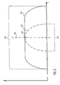
- a distribution of wavelengths 360 having a narrower spectrum 350 (corresponding to the narrower of the pass bands of filters 170, 180 of Figure 1 ) within that of the broadband energy spectrum 320 will cause interference and result in periodically varying intensity fluctuations with change of air gap length.
- the center frequency or wavelength of the broadband energy from the source or as filtered at 170 or 180 need not be the same as the center frequency or wavelength 305' of the narrow band 360 as long as the narrow band is within a relatively flat region of the broadband spectrum 320.
- the length of the (doubled) air gap determines the proportion of incident energy which results in interference of a component of the energy reflected from the sensor as well as the average power seen in the average interference pattern.
- the power observed at the detector (175 or 185) of portions of the broadband spectrum 320 within narrow band 350, 360 having a coherence length greater than the doubled air gap and causing interference will also increase or decrease.
- the observed power in the interference pattern will also change strongly with changes in air gap length for each arbitrary band within the narrow band filtered beam and will also be strongly observed on average over pass band 350.
- the ratio of energies or optical powers of the spectrum 320 and the partial spectrum 350 as observed in a fringe of the interference pattern will thus provide a measure of the parameter of interest.
- the air gap 260 of the sensor 150 must be selected in such a way that the air gap is longer than the coherence length of full broadband spectrum 330 but shorter than the coherence length of a narrower spectrum (e.g. corresponding to the filter pass band 350) which will be of suitable optical power to be detected with good resolution after filtration at 170, 180 by photosensors 175, 185.
- a narrower spectrum e.g. corresponding to the filter pass band 350
- Filters 170, 180 are preferably band-pass filters having the same or similar (depending on the "flatness" of the broadband spectrum) center frequencies but different spectral bandwidths; the narrower bandwidth corresponding to a nominal value of the doubled air gap of the sensor such that the coherence length of the pass-band of the filter is much longer than the doubled air gap.
- the optical power in each of the two channels produced by beam-splitter 160, after filtering, will have very different sensitivities to changes in the length of the air gap which will be reflected in the relative optical power of the respective filtered beams, as discussed above.
- ambiguity can be introduced into the measurement provided by the transducer unless resolved by fringe counting or phase tracking which is usually sophisticated and costly preventing absolute measurements.
- fringe counting or phase tracking which is usually sophisticated and costly preventing absolute measurements.
- the introduction of ambiguity can be avoided and any need for fringe counting or phase tracking eliminated by designing the sensor with an air gap having limited variation of length with monitored conditions.
- a short air gap is preferred to increase maximum power and power variation observable in the signal (since observability of interference effects and power therein diminishes with air gap length, as alluded to above) and to avoid excess sensitivity to the parameter of interest as well as to minimize overall dimensions of the transducer.
- sensitivity to change of the measured parameter can be readily understood since a given change in, for example, temperature or pressure will result in a change of air gap length which will be proportional length of the transducer affected by the measured parameter and which is generally coextensive with air gap length.
- a very short air gap on the order of a few microns to a few tens of microns generally assures both sufficient power for measurements of high accuracy and resolution while avoiding the need for system complexities such as fringe counting to avoid measurement ambiguity. If necessary to provide coverage of wide variation of values of a parameter of interest, the sensitivity of the transducer can be further limited as discussed below.
- This feature of the preferred form of the invention also allows the transducer to be formed at very small size (e.g. 150 ⁇ m in diameter and 300 ⁇ m in length) and of high robustness.
- the hollow sleeve portion 230 is not involved in the optical effects exploited by the transducer and thus can be fabricated from any desired material (e.g. to resist corrosion to choose a particular coefficients of expansion, etc. in any combination) and may, if desired or advantageous in a particular environment, enclose the salient or distal end of the reflecting fiber or other reflecting structure 220, such as a diaphragm for sensing of fluid pressure.
- Differences in the optical power of the filtered beams may be derived in several different ways in accordance with the principles of the invention.
- the bandwidth of the broadband light source is very large, consistent with maintaining highest possible light intensity through the system for greatest practical monitoring distance and length of optical fiber 140 and high sensitivity to very small variations in air gap length with small changes in the parameter of interest, it is desirable to choose a narrow-band filter which sets the pass band 350 at a range significantly larger than that corresponding to coherence length at an extreme measurement anticipated for the transducer.
- filtering is not necessary in both channels and can be provided in only one channel if the broadband spectrum of the light source is well-defined and relatively stable, as in the case of a light-emitting diode. That is, while output spectra of light-emitting diodes are known to vary significantly but predictably with substantial excursions of temperature, in the case of the present invention, temperature can be readily controlled since the light source is located at the detector end of the fiber. In such a case, it is sufficient to provide a single filter (e.g. 185) of significantly narrower bandwidth for limitation of its output to observe interference in order to successfully practice the invention.
- a narrow pass band filter in combination with a light-emitting diode is a particularly desirable combination to implement the invention since the spectral content of a light-emitting diode is substantially invariant over time and can be more efficiently coupled to an optical fiber than white light sources.
- Figures 4 and 5 for preferred forms of temperature and pressure sensors which are either fully or substantially immune to effects of other environmental conditions.
- Figure 4 shows a sensor 150, as shown in Figure 2 , as well, for discussion of providing for temperature compensation during pressure or strain measurement.
- Figure 5 shows a temperature sensor including adaptations which, while not providing complete compensation for pressure variations, at least provides limitation of pressure effects on the temperature measurement.
- Exact compensation can be achieved by proportioning the CTE's of the lead-in and reflecting fibers and the CTE of the hollow sleeve 230 and the locations where the fibers are bonded to the sleeve such that the ratio of the CTE of the sleeve to the CTEs of the fibers is d+d':d+d'+g. It can be understood that when g becomes small relative to d and/or d', as would usually the case in view of the preferred short air gap as described above, the difference between substantial and exact compensation becomes vanishingly small.
- sensitivity to strain or pressure and range of measurement can be varied by choice of d and d' relative to the distance between bonds 240 preferably chosen to keep the gap variation within one-quarter of the center wavelength constraint described above.
- Choice of material for sleeve 230 to have an increased Young's modulus of elasticity may extend the measurement range for given values of d and d' at the expense of resolution and sensitivity.
- pressure and strain effects can be further precorrected by adjustment of nominal fluid pressure in the air gap to counteract such forces at a nominal working temperature and the transducer suitably calibrated accordingly.
- pressure and strain corrections are generally small if the transducer itself is no longer than necessary since even large forces will cause only a change of a small percentage of sensor length.
- corrections for pressure and/or strain may be relatively negligible or susceptible of substantially complete correction based on calibration and rough estimates of pressure and/or strain.
- the invention provides for temperature, pressure or strain measurement over large distances and with high accuracy and resolution while providing compensation or at least minimization of effects of those physical parameters other than the parameter of interest with simple, intensity based signal detection and processing.
- Energy source and fiber transmission loss variations are fully compensated.
- the transducer is simple, inexpensive to fabricate, extremely small and robust and, depending on materials, resists flammable and corrosive environments. Moreover, no optical filtering is required in the transducer and only reflections which are immune to environmental conditions are employed.
Landscapes
- Physics & Mathematics (AREA)
- General Physics & Mathematics (AREA)
- Optical Transform (AREA)
- Length Measuring Devices By Optical Means (AREA)
- Measuring Fluid Pressure (AREA)
- Investigating Strength Of Materials By Application Of Mechanical Stress (AREA)
- Measuring Temperature Or Quantity Of Heat (AREA)
Claims (17)
- Un dispositif de mesure à fibres optiques y compris une source d'énergie à large bande (110) et un transducteur (150) chargé de recevoir ladite énergie à large bande et se caractérisant de la façon suivante :Ledit transducteur a un entrefer (260) implanté entre les interfaces réflectives (211, 221) et dont la longueur (d) est supérieure à plus de la moitié de la longueur de cohérence de ladite énergie à large bande et, en outre, ledit dispositif comporte :un filtre à bande passante (170 ou 180) dont la bande passante est inférieure au contenu spectral de ladite énergie à bande passante et dont la longueur de cohérence est égale à plus de deux fois ladite longueur dudit entrefer etdes dispositifs (160, 170, 175, 180, 185) qui permettent de déterminer un rapport énergétique sur une portion de ladite énergie à large bande réfléchie par ledit transducteur dont la longueur de cohérence est égale à moins de deux fois que ladite longueur dudit entrefer et dont l'énergie de l'autre portion de ladite énergie à large bande réfléchie par ledit transducteur a une longueur de cohérence égale à plus de deux fois celle de ladite longueur dudit entrefer.
- Un dispositif identique à celui qui est décrit dans l'affirmation 1, si ce n'est que ledit dispositif de détermination d'un rapport comporte un diviseur de faisceau (160).
- Un dispositif identique à celui qui est décrit dans l'affirmation 1 mais qui comporte en outre un dispositif (155) de collimation de l'énergie réfléchie depuis ledit transducteur.
- Un dispositif identique à celui qui est mentionné dans l'affirmation 3, si ce n'est que ledit dispositif de collimation comporte un index gradué de l'élément optique de réfraction (155).
- Un dispositif identique à celui qui est décrit dans l'affirmation 1, si ce n'est que ladite source d'énergie à large bande (110) comporte une source lumineuse de type tungstène-halogène.
- Un dispositif identique à celui qui est décrit dans l'affirmation 1, si ce n'est que ladite source d'énergie à large bande (110) comporte une diode électroluminescente.
- Un dispositif identique à celui qui est décrit dans l'affirmation 1, si ce n'est que ladite source d'énergie à large bande (110) comporte une diode superluminescente.
- Un dispositif identique à celui qui est décrit dans l'affirmation 1, si ce n'est que ladite source d'énergie à large bande (110) comporte une pluralité de sources lumineuses monochromatiques.
- Un dispositif identique à celui qui est décrit dans l'affirmation 1, si ce n'est que lesdites interfaces (211, 221) sont métallisées.
- Un dispositif identique à celui qui est décrit dans l'affirmation 1, si ce n'est qu'une des interfaces (211, 221) comporte une membrane.
- Une méthode de mesure de la température, la pression ou la contrainte y compris un élément pour réfléchir l'énergie à large bande provenant de deux interfaces espacées l'une de l'autre (211, 221) afin de définir un entrefer (260), si ce n'est que la longueur (d) dudit entrefer varie en fonction de la température, la pression ou la contrainte et se caractérisant de la façon suivante :ladite énergie à large bande a une longueur de cohérence égale à moins de la moitié de la longueur dudit entrefer,la bande passante (170 ou 180) filtre une portion de l'énergie à large bande réfléchie en conformité avec une bande passante qui correspond à une longueur de cohérence plus de deux fois supérieure audit entrefer etcomparaison de la puissance de ladite portion de l'énergie à large bande réfléchie filtrée au dit élément de filtrage de bande passante alors que la puissance d'une autre portion de ladite énergie à bande passante réfléchie a une bande spectrale plus large que celle qui passe dans ledit élément de filtrage.
- Une méthode identique à celle qui est décrite dans l'affirmation 11 mais comportant en outre l'élément de collimation (155) de ladite source lumineuse à large bande réfléchie par ledit élément réfléchissant.
- Une méthode identique à celle qui est décrite dans l'affirmation 11 mais comportant en outre l'élément de division (160) de ladite énergie à large bande réfléchie par ledit élément réfléchissant en vue de former plusieurs faisceaux.
- Une méthode identique à celle qui est décrite dans l'affirmation 11 mais comportant en outre l'élément de filtrage de bande passante (180 ou 170) de ladite autre portion de ladite énergie à large bande en conformité avec une bande passante et correspondant à une longueur de cohérence égale à moins de deux fois ledit espacement entre lesdites interfaces.
- Un système identique à celui qui est décrit dans l'une ou l'autre des revendications 1 à 10 et comportant en outre un dispositif permettant de limiter les changements dudit espacement desdites deux interfaces réflectives sur une plage de mesures allant jusqu'à un quart d'une longueur d'onde de l'énergie incluse dans ladite énergie à large bande.
- Un système identique à celui qui est décrit dans l'affirmation 15 mais comportant en outre un liquide venant s'intercaler entre lesdites interfaces.
- Une méthode identique à celle qui est décrite dans l'une ou l'autre des revendications 11 à 14 et comportant en outre l'élément supplémentaire de limitation des changements de l'espacement séparant lesdites interfaces sur toute une plage de mesures allant jusqu'à un quart d'une longueur d'onde de l'énergie incluse dans ladite énergie à large bande.
Applications Claiming Priority (3)
| Application Number | Priority Date | Filing Date | Title |
|---|---|---|---|
| US904315 | 1997-07-31 | ||
| US08/904,315 US5963321A (en) | 1997-07-31 | 1997-07-31 | Self-calibrating optical fiber pressure, strain and temperature sensors |
| PCT/US1998/015600 WO1999006795A1 (fr) | 1997-07-31 | 1998-07-29 | Capteur de temperature, capteur extensometrique et capteur de pression a fibres optiques et a etalonnage automatique |
Publications (3)
| Publication Number | Publication Date |
|---|---|
| EP1007902A1 EP1007902A1 (fr) | 2000-06-14 |
| EP1007902A4 EP1007902A4 (fr) | 2007-05-02 |
| EP1007902B1 true EP1007902B1 (fr) | 2009-03-11 |
Family
ID=25418931
Family Applications (1)
| Application Number | Title | Priority Date | Filing Date |
|---|---|---|---|
| EP98938053A Expired - Lifetime EP1007902B1 (fr) | 1997-07-31 | 1998-07-29 | Capteur de temperature, capteur extensometrique et capteur de pression a fibres optiques et a etalonnage automatique |
Country Status (8)
| Country | Link |
|---|---|
| US (2) | US5963321A (fr) |
| EP (1) | EP1007902B1 (fr) |
| AU (1) | AU8666498A (fr) |
| CA (1) | CA2298693C (fr) |
| DE (1) | DE69840651D1 (fr) |
| ID (1) | ID24659A (fr) |
| NO (1) | NO317221B1 (fr) |
| WO (1) | WO1999006795A1 (fr) |
Families Citing this family (45)
| Publication number | Priority date | Publication date | Assignee | Title |
|---|---|---|---|---|
| US5832157A (en) * | 1996-07-12 | 1998-11-03 | Mcdermott Technology, Inc. | Fiber optic acoustic emission sensor |
| JP3549153B2 (ja) * | 2000-09-20 | 2004-08-04 | 株式会社共和電業 | 光ファイバ干渉センサ、光ファイバ干渉センサの信号処理システム、信号処理方法および記録媒体 |
| US7154659B1 (en) * | 2002-04-18 | 2006-12-26 | General Photonics Corporation | Optical depolarizers and DGD generators based on optical delay |
| WO2003098156A1 (fr) * | 2002-05-17 | 2003-11-27 | Sensor Highway Limited | Capteur distant interferometrique a fibres optiques |
| GB0211388D0 (en) * | 2002-05-17 | 2002-06-26 | Sensor Highway Ltd | Light source stabilisation |
| US20040047536A1 (en) * | 2002-09-05 | 2004-03-11 | Pickrell Gary R. | Creep and viscous flow resistant fiber optic sensor |
| AU2003278933A1 (en) * | 2002-09-26 | 2004-04-19 | Prime Photonics, Inc. | Active q-point stabilization for linear interferometric sensors |
| US6922231B1 (en) * | 2003-01-23 | 2005-07-26 | Opnext, Inc. | Receiver optical sub-assembly with diagnostic signal |
| US7104141B2 (en) * | 2003-09-04 | 2006-09-12 | Baker Hughes Incorporated | Optical sensor with co-located pressure and temperature sensors |
| EP1664706B1 (fr) * | 2003-09-04 | 2011-07-27 | Baker Hughes Incorporated | Capteur optique avec capteurs de pression et de temperature co-implantes |
| BRPI0414871A (pt) * | 2003-10-03 | 2006-11-28 | Sabeus Inc | sensor de pressão fabry-perot reforçado |
| US7173713B2 (en) * | 2004-03-04 | 2007-02-06 | Virginia Tech Intellectual Properties, Inc. | Optical fiber sensors for harsh environments |
| US20050195402A1 (en) * | 2004-03-04 | 2005-09-08 | Russell May | Crystalline optical fiber sensors for harsh environments |
| US7492463B2 (en) * | 2004-04-15 | 2009-02-17 | Davidson Instruments Inc. | Method and apparatus for continuous readout of Fabry-Perot fiber optic sensor |
| US7305158B2 (en) * | 2004-04-15 | 2007-12-04 | Davidson Instruments Inc. | Interferometric signal conditioner for measurement of absolute static displacements and dynamic displacements of a Fabry-Perot interferometer |
| US7134346B2 (en) * | 2004-04-15 | 2006-11-14 | Davidson Instruments Inc. | Differential pressure transducer with Fabry-Perot fiber optic displacement sensor |
| US7355726B2 (en) * | 2004-04-15 | 2008-04-08 | Davidson Instruments Inc. | Linear variable reflector sensor and signal processor |
| US7835598B2 (en) * | 2004-12-21 | 2010-11-16 | Halliburton Energy Services, Inc. | Multi-channel array processor |
| US7864329B2 (en) * | 2004-12-21 | 2011-01-04 | Halliburton Energy Services, Inc. | Fiber optic sensor system having circulators, Bragg gratings and couplers |
| EP1869737B1 (fr) * | 2005-03-16 | 2021-05-12 | Davidson Instruments, Inc. | Capteur fabry-perot haute intensite |
| WO2007033069A2 (fr) * | 2005-09-13 | 2007-03-22 | Davidson Instruments Inc. | Algorithme de poursuite pour processeur de signal a reseau lineaire a schemas de correlation croisee de fabry-perot et son procede d'utilisation |
| US7684051B2 (en) * | 2006-04-18 | 2010-03-23 | Halliburton Energy Services, Inc. | Fiber optic seismic sensor based on MEMS cantilever |
| US7743661B2 (en) * | 2006-04-26 | 2010-06-29 | Halliburton Energy Services, Inc. | Fiber optic MEMS seismic sensor with mass supported by hinged beams |
| US8115937B2 (en) * | 2006-08-16 | 2012-02-14 | Davidson Instruments | Methods and apparatus for measuring multiple Fabry-Perot gaps |
| US7787128B2 (en) * | 2007-01-24 | 2010-08-31 | Halliburton Energy Services, Inc. | Transducer for measuring environmental parameters |
| JP5274862B2 (ja) * | 2008-03-10 | 2013-08-28 | 東京エレクトロン株式会社 | 温度測定装置及び温度測定方法 |
| US8515675B2 (en) * | 2008-04-02 | 2013-08-20 | Bakes Hughes Incorporated | Method for analyzing strain data |
| DE102008017740A1 (de) * | 2008-04-07 | 2009-10-15 | Lios Technology Gmbh | Vorrichtung und Verfahren zur Kalibrierung eines faseroptischen Temperaturmesssystems |
| US8195013B2 (en) * | 2009-08-19 | 2012-06-05 | The United States Of America, As Represented By The Secretary Of The Navy | Miniature fiber optic temperature sensors |
| DE102009058520B4 (de) * | 2009-12-16 | 2015-08-27 | Bundesanstalt für Materialforschung und -Prüfung (BAM) | Vorrichtung und Verfahren zur schnellen Dehnungsmessung |
| US8558994B2 (en) * | 2010-01-12 | 2013-10-15 | Baker Hughes Incorporated | EFPI sensor |
| US8793102B2 (en) * | 2010-01-12 | 2014-07-29 | Baker Hughes Incorporated | Multi-gap interferometric sensors |
| US9194973B2 (en) | 2010-12-03 | 2015-11-24 | Baker Hughes Incorporated | Self adaptive two dimensional filter for distributed sensing data |
| US9103736B2 (en) | 2010-12-03 | 2015-08-11 | Baker Hughes Incorporated | Modeling an interpretation of real time compaction modeling data from multi-section monitoring system |
| US9557239B2 (en) | 2010-12-03 | 2017-01-31 | Baker Hughes Incorporated | Determination of strain components for different deformation modes using a filter |
| US9574949B2 (en) | 2012-02-17 | 2017-02-21 | Roctest Ltd | Automated system and method for testing the efficacy and reliability of distributed temperature sensing systems |
| WO2013139783A1 (fr) * | 2012-03-22 | 2013-09-26 | University Of Limerick | Capteur pour la détection associée d'une température, d'une pression, et d'un indice de réfraction |
| GB2503466B (en) * | 2012-06-27 | 2017-04-19 | Oxsensis Ltd | Optical sensor |
| US9658171B2 (en) * | 2013-05-20 | 2017-05-23 | Habsonic LLC | Optical carrier based microwave interferometric system and method |
| US9605534B2 (en) | 2013-11-13 | 2017-03-28 | Baker Hughes Incorporated | Real-time flow injection monitoring using distributed Bragg grating |
| US9677935B2 (en) * | 2014-11-03 | 2017-06-13 | Trutag Technologies, Inc. | Fabry-perot spectral image measurement |
| US9448312B1 (en) | 2015-03-11 | 2016-09-20 | Baker Hughes Incorporated | Downhole fiber optic sensors with downhole optical interrogator |
| CN106802191B (zh) * | 2017-01-19 | 2019-03-29 | 长飞光纤光缆股份有限公司 | 一种嵌入式低温光纤温度传感器及其制备方法 |
| CA3083731C (fr) * | 2017-11-10 | 2023-02-28 | Baker Hughes, A Ge Company, Llc | Capteur interferometrique entierement en verre a cavites multiples pour mesurer une pression et une temperature elevees |
| PL236751B1 (pl) * | 2018-06-18 | 2021-02-08 | Inphotech Spolka Z Ograniczona Odpowiedzialnoscia | Czujnik falowodowy |
Family Cites Families (4)
| Publication number | Priority date | Publication date | Assignee | Title |
|---|---|---|---|---|
| US5301001A (en) * | 1992-02-12 | 1994-04-05 | Center For Innovative Technology | Extrinsic fiber optic displacement sensors and displacement sensing systems |
| US5202939A (en) * | 1992-07-21 | 1993-04-13 | Institut National D'optique | Fabry-perot optical sensing device for measuring a physical parameter |
| US5446280A (en) * | 1993-08-31 | 1995-08-29 | Center For Innovative Technology | Split-spectrum self-referenced fiber optic sensor |
| CA2105605A1 (fr) * | 1993-09-07 | 1995-03-08 | Zhuo Jun Lu | Systeme a reseau de capteurs a fibres optiques servant a la mesure des deformations et des temperatures |
-
1997
- 1997-07-31 US US08/904,315 patent/US5963321A/en not_active Expired - Lifetime
-
1998
- 1998-07-28 AU AU86664/98A patent/AU8666498A/en not_active Abandoned
- 1998-07-29 CA CA002298693A patent/CA2298693C/fr not_active Expired - Fee Related
- 1998-07-29 ID IDW20000187A patent/ID24659A/id unknown
- 1998-07-29 WO PCT/US1998/015600 patent/WO1999006795A1/fr not_active Ceased
- 1998-07-29 EP EP98938053A patent/EP1007902B1/fr not_active Expired - Lifetime
- 1998-07-29 DE DE69840651T patent/DE69840651D1/de not_active Expired - Fee Related
-
1999
- 1999-05-11 US US09/309,660 patent/US6069686A/en not_active Expired - Lifetime
-
2000
- 2000-01-31 NO NO20000500A patent/NO317221B1/no not_active IP Right Cessation
Also Published As
| Publication number | Publication date |
|---|---|
| NO20000500L (no) | 2000-03-31 |
| US6069686A (en) | 2000-05-30 |
| US5963321A (en) | 1999-10-05 |
| CA2298693C (fr) | 2005-09-27 |
| ID24659A (id) | 2000-07-27 |
| AU8666498A (en) | 1999-02-22 |
| NO20000500D0 (no) | 2000-01-31 |
| EP1007902A1 (fr) | 2000-06-14 |
| DE69840651D1 (de) | 2009-04-23 |
| NO317221B1 (no) | 2004-09-20 |
| CA2298693A1 (fr) | 1999-02-11 |
| WO1999006795A1 (fr) | 1999-02-11 |
| EP1007902A4 (fr) | 2007-05-02 |
Similar Documents
| Publication | Publication Date | Title |
|---|---|---|
| EP1007902B1 (fr) | Capteur de temperature, capteur extensometrique et capteur de pression a fibres optiques et a etalonnage automatique | |
| US5646401A (en) | Fiber optic grating and etalon sensor systems | |
| CN107024236B (zh) | F-p/fbg光纤传感器解调系统 | |
| US10545035B2 (en) | Optical sensor with one or more sensing interference elements | |
| US4329058A (en) | Method and apparatus for a Fabry-Perot multiple beam fringe sensor | |
| US7684656B2 (en) | Fiber optic temperature and pressure sensor and system incorporating same | |
| US5202939A (en) | Fabry-perot optical sensing device for measuring a physical parameter | |
| US20080085073A1 (en) | Dynamic optical waveguide sensor | |
| US5446280A (en) | Split-spectrum self-referenced fiber optic sensor | |
| US9164027B2 (en) | Frequency tunable laser system | |
| CN102003944A (zh) | 共路补偿的多尺度准分布式白光干涉应变测量装置及方法 | |
| CA1203701A (fr) | Sonde de luminescence a fibre optique avec couche mince d'interference | |
| CA2450988A1 (fr) | Systeme de mesure differentielle base sur l'utilisation de paires de reseaux de bragg | |
| AU2020103491A4 (en) | A twin array Michelson fiber optic white light interferometry strain gauge | |
| AU2020103584A4 (en) | A distributed fiber white light interferometric sensor array based on a tunable Fabry-Perot resonant cavity | |
| AU732668B2 (en) | TDM array of optical non-acoustic pressure sensors | |
| US6414303B1 (en) | High accuracy Bragg grating based pressure sensor with dual resolution mode | |
| Dakin et al. | New multiplexing scheme for monitoring fiber optic Bragg grating sensors in the coherence domain | |
| Shlyagin et al. | Twin grating-based interferometric fiber sensor | |
| CN207439428U (zh) | 实现光纤f-p和fbg传感器的解调装置 | |
| US6038926A (en) | TDM array of optical non-acoustic pressure sensors | |
| Egorov et al. | Spectrally encoded fiber optic sensors based on Fabry-Perot interferometer | |
| Ushakov et al. | Utilization of NI PXIe-4844 interrogator for high resolution fiber extrinsic Fabry-Perot interferometric sensing | |
| Jones et al. | Multimode optical fiber sensors | |
| Shlyagin et al. | Interferometric quasi-distributed fiber optic sensor using pointlike polarization couplers |
Legal Events
| Date | Code | Title | Description |
|---|---|---|---|
| PUAI | Public reference made under article 153(3) epc to a published international application that has entered the european phase |
Free format text: ORIGINAL CODE: 0009012 |
|
| 17P | Request for examination filed |
Effective date: 20000302 |
|
| AK | Designated contracting states |
Kind code of ref document: A1 Designated state(s): DE DK FR GB NL |
|
| A4 | Supplementary search report drawn up and despatched |
Effective date: 20070212 |
|
| RIC1 | Information provided on ipc code assigned before grant |
Ipc: G01L 1/24 20060101ALI20070206BHEP Ipc: G01D 5/26 20060101AFI20070206BHEP |
|
| 17Q | First examination report despatched |
Effective date: 20071102 |
|
| GRAP | Despatch of communication of intention to grant a patent |
Free format text: ORIGINAL CODE: EPIDOSNIGR1 |
|
| GRAS | Grant fee paid |
Free format text: ORIGINAL CODE: EPIDOSNIGR3 |
|
| GRAA | (expected) grant |
Free format text: ORIGINAL CODE: 0009210 |
|
| AK | Designated contracting states |
Kind code of ref document: B1 Designated state(s): DE DK FR GB NL |
|
| REG | Reference to a national code |
Ref country code: GB Ref legal event code: FG4D |
|
| REF | Corresponds to: |
Ref document number: 69840651 Country of ref document: DE Date of ref document: 20090423 Kind code of ref document: P |
|
| PG25 | Lapsed in a contracting state [announced via postgrant information from national office to epo] |
Ref country code: NL Free format text: LAPSE BECAUSE OF FAILURE TO SUBMIT A TRANSLATION OF THE DESCRIPTION OR TO PAY THE FEE WITHIN THE PRESCRIBED TIME-LIMIT Effective date: 20090311 |
|
| NLV1 | Nl: lapsed or annulled due to failure to fulfill the requirements of art. 29p and 29m of the patents act | ||
| PLBE | No opposition filed within time limit |
Free format text: ORIGINAL CODE: 0009261 |
|
| STAA | Information on the status of an ep patent application or granted ep patent |
Free format text: STATUS: NO OPPOSITION FILED WITHIN TIME LIMIT |
|
| PG25 | Lapsed in a contracting state [announced via postgrant information from national office to epo] |
Ref country code: DK Free format text: LAPSE BECAUSE OF FAILURE TO SUBMIT A TRANSLATION OF THE DESCRIPTION OR TO PAY THE FEE WITHIN THE PRESCRIBED TIME-LIMIT Effective date: 20090311 |
|
| 26N | No opposition filed |
Effective date: 20091214 |
|
| REG | Reference to a national code |
Ref country code: FR Ref legal event code: ST Effective date: 20100331 |
|
| PG25 | Lapsed in a contracting state [announced via postgrant information from national office to epo] |
Ref country code: FR Free format text: LAPSE BECAUSE OF NON-PAYMENT OF DUE FEES Effective date: 20090731 |
|
| PG25 | Lapsed in a contracting state [announced via postgrant information from national office to epo] |
Ref country code: DE Free format text: LAPSE BECAUSE OF NON-PAYMENT OF DUE FEES Effective date: 20100202 |
|
| PGFP | Annual fee paid to national office [announced via postgrant information from national office to epo] |
Ref country code: GB Payment date: 20100726 Year of fee payment: 13 |
|
| GBPC | Gb: european patent ceased through non-payment of renewal fee |
Effective date: 20110729 |
|
| PG25 | Lapsed in a contracting state [announced via postgrant information from national office to epo] |
Ref country code: GB Free format text: LAPSE BECAUSE OF NON-PAYMENT OF DUE FEES Effective date: 20110729 |