EP1007911B1 - Dispositif et procede pour la determination du debit d'extraction ou du debit massique de matieres extraites a transporter au moyen d'une pompe a piston pour liquides epais - Google Patents
Dispositif et procede pour la determination du debit d'extraction ou du debit massique de matieres extraites a transporter au moyen d'une pompe a piston pour liquides epais Download PDFInfo
- Publication number
- EP1007911B1 EP1007911B1 EP97918994A EP97918994A EP1007911B1 EP 1007911 B1 EP1007911 B1 EP 1007911B1 EP 97918994 A EP97918994 A EP 97918994A EP 97918994 A EP97918994 A EP 97918994A EP 1007911 B1 EP1007911 B1 EP 1007911B1
- Authority
- EP
- European Patent Office
- Prior art keywords
- housing
- conveyance
- piston
- conveyance cylinder
- cylinder
- Prior art date
- Legal status (The legal status is an assumption and is not a legal conclusion. Google has not performed a legal analysis and makes no representation as to the accuracy of the status listed.)
- Expired - Lifetime
Links
Images


Classifications
-
- G—PHYSICS
- G01—MEASURING; TESTING
- G01G—WEIGHING
- G01G11/00—Apparatus for weighing a continuous stream of material during flow; Conveyor belt weighers
- G01G11/02—Apparatus for weighing a continuous stream of material during flow; Conveyor belt weighers having mechanical weight-sensitive devices
Definitions
- the invention relates to an arrangement for determination the flow rate or the mass flow by means of a having at least one delivery cylinder and delivery piston Piston thick pump through a delivery line transported goods.
- the feed cylinder is during a filling stroke (suction stroke) with material to be conveyed, for example filled from a material feed container and during a pressure stroke while displacing the conveyed material emptied into the delivery line.
- Volume counters in the form of oval wheel counters are known for Newtonian fluids that act as "motor” in the Delivery line are installed and where a volume wheel set in rotation as a result of the pumping process. The revolutions of the volume wheel are measured by a pulse disk added up and in an evaluation unit of the known displacement volume in a volume flow converted.
- the invention is based on the object an arrangement and a method for determination the flow rate or the mass flow of the initially specified Way to develop, even with fluctuating Degree of filling of the delivery cylinders and within wide limits variable consistency of the conveyed goods an exact Measurement is possible.
- the solution according to the invention is based on the method thought that the feed cylinder before execution each filling stroke and before executing one weighed each pressure stroke and from the difference of Weighing results the respective filling quantity is determined and that the cycle time of each stroke cycle is measured and taking into account the measured filling quantities for the mathematical determination of the delivery rate or the Mass flow is evaluated.
- the feed cylinder in a housing with radial and axial play arranged and at least a load cell fixed to the housing is.
- the load cell enables especially in the reverse phases of the delivery piston before the filling stroke is carried out and an exact one before executing the pressure stroke Mass determination of the empty and full conveyor cylinders including delivery piston, so that each time Difference formation the filling quantity can be determined.
- At least the one in the feed cylinder guided part of the delivery piston relative to the housing radial play is suspended. This can be achieved be that the delivery piston on its piston rod preferably gimbaled with radial play is and / or that the delivery piston compared to the Housing or its piston rod suspended elastically is.
- the housing as the feed cylinder outside round tube or polygonal tube is and that at the top of the housing two Load cells arranged axially apart are.
- the load cells are expediently attached to a housing Storage platform arranged and have one a strain gauge equipped spring body, while the delivery cylinder by means of a the housing a wall opening radially penetrating support rod is suspended from the spring bodies.
- the spring body can, for example, as a bending beam, double bending beam or shear bar.
- the wall breakthrough should avoid falsifying the measurement Contamination from between the plunger and the housing wall clamped bellows are sealed.
- a two-cylinder slurry pump are useful two in one housing with radial and axial play arranged, suspended from the housing via load cells Delivery cylinder provided, the delivery piston with hydraulic Means can be driven in push-pull.
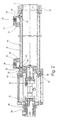
- the two-cylinder high-pressure piston pump shown schematically in FIG. 1 10 consists essentially of two delivery cylinders 12, the front openings 14 into a via a twin-screw mixer 16
- Material feed container 18 that can be loaded with thick materials open and alternately during the pressure stroke of their delivery pistons 20 via a pipe switch 22 with a delivery line 24 connectable and during the suction or filling stroke of the relevant delivery piston 20 under suction of conveyed material to the material feed container 18 open are.
- the delivery pistons 20 are driven by hydraulic drive cylinders 26 driven in push-pull. Between the drive cylinders 26 and the feed cylinders 12 a water box 28 for cleaning the between the drive cylinders 26 and the feed cylinders 12 penetrating piston rods 29.
- Pumped goods are the delivery cylinders 12 floating in a tubular housing 30 stored and on weighing devices 32 fixed to the housing hung up.
- the weighing devices 32 each contain one housing-fixed bearing platform 34, one from one with one Strain gauges equipped as bending beams Existing load cell 36 and an am free end of the bending beam of the load cell 36, through an opening 38 of the housing 30 and with its other end on the outer surface of the feed cylinder 12 attached support rod 40.
- the Breakthrough 38 is to avoid contamination by a clamped between support rod 40 and housing 30 Bellows 39 sealed.
- the feed cylinder 12 is at its one end on the loading side 41 on an axially elastic on a housing-fixed Seal carrier 42 supported metallic slide ring 44 supported radially displaceably and via an elastic compliant quad ring seal 46 with radial Play in the seal carrier 42 stored.
- On its drive side The end of 48 is the delivery cylinder 12 with axial play radially displaceable against one for assembly purposes removable and adjustable stop ring 49 on.
- the delivery cylinder 12 also engages in the area of its drive-side end 48 by a housing-fixed Guide sleeve 50 with radial play through.
- the filling quantities calculated in this way can take into account the also measurable Number of strokes or stroke frequency for determining the mass flow through the delivery line 24 and the total delivery rate be evaluated.
- the invention relates to an arrangement and a method to determine the flow rate or mass flow by means of a piston nitrogen pump 10 through a Conveying line 24 transported goods.
- the exact one Determination of the sizes mentioned is made possible by that the feed cylinder 12 in a housing 30 with radial and axial play arranged and at least a load cell 36 arranged fixed to the housing is.
Landscapes
- Physics & Mathematics (AREA)
- General Physics & Mathematics (AREA)
- Details Of Reciprocating Pumps (AREA)
- Reciprocating Pumps (AREA)
- Structures Of Non-Positive Displacement Pumps (AREA)
Claims (15)
- Dispositif pour déterminer le débit ou le débit massique d'une matière transportée à travers une conduite (24) au moyen d'une pompe pour liquides épais (10) présentant au moins un cylindre (12) et un piston (20), caractérisé en ce que le cylindre (12) est disposé dans un carter (30) avec un jeu radial et axial, et est suspendu à au moins une cellule de pesage (36) disposée fixement sur le carter.
- Dispositif selon la revendication 1, caractérisé en ce qu'au moins la partie du piston (20) qui est guidée dans le cylindre (12) est suspendue avec un jeu radial par rapport au carter (30).
- Dispositif selon la revendication 2, caractérisé en ce que le piston (20) est suspendu par sa tige avec un jeu radial de préférence à la Cardan.
- Dispositif selon la revendication 2 ou 3, caractérisé en ce que le piston (20) est suspendu de manière élastique par rapport au carter (30) ou à sa tige (29).
- Dispositif selon l'une des revendications 1 à 4, caractérisé en ce que le carter (30) est réalisé en tant que tube rond ou polygonal entourant le cylindre (12).
- Dispositif selon l'une des revendications 1 à 5, caractérisé en ce que le cylindre (12) est orienté horizontalement à l'intérieur du carter (30), et en ce que deux cellules de pesage (36) sont disposées avec un écartement axial sur le dessus du carter.
- Dispositif selon la revendication 6, caractérisé en ce que les cellules de pesage (36) présentent un élément à ressort disposé sur un socle (34) solidaire du carter et muni d'une bande de mesure de l'allongement, et en ce que le cylindre (12) est suspendu à l'élément à ressort au moyen d'une barre de support (40) passant à travers le carter (30) au niveau d'un passage dans la paroi (38).
- Dispositif selon la revendication 7, caractérisé en ce que l'élément à ressort est réalisé en tant que poutre de flexion, double poutre de flexion ou barre de cisaillement.
- Dispositif selon la revendication 7 ou 8, caractérisé en ce que le passage de la paroi (38) est étanché par un soufflet (39) serré entre la barre de support (40) et la paroi de carter (30).
- Dispositif selon l'une des revendications 1 à 9, caractérisé en ce que le cylindre (12) peut prendre appui avec son extrémité (41) située côté alimentation sur une bague de glissement (44) métallique prenant appui sur le carter (30) de manière élastique dans la direction axiale, de façon à pouvoir coulisser radialement.
- Dispositif selon l'une des revendications 1 à 10, caractérisé en ce que le cylindre (12) est monté dans le carter (30) avec un jeu radial par l'intermédiaire d'une bague d'étanchéité élastique de section carrée (46).
- Dispositif selon l'une des revendications 1 à 11, caractérisé en ce que le cylindre (12) est appliqué avec un jeu axial avec son extrémité située côté moteur (48) contre une bague de butée (49) de façon à être mobile radialement.
- Dispositif selon l'une des révendications 1 à 12, caractérisé en ce que le cylindre traverse avec un jeu radial, dans la zone de son extrémité située côté moteur (48), une douille de guidage (50) solidaire du carter.
- Dispositif selon l'une des revendications 1 à 13, caractérisé en ce que sont prévus deux cylindres (12) disposés dans le carter (30) avec un jeu axial et radial et suspendus au carter (30) par le biais de cellules de pesage (36), dont les pistons (20) peuvent être entraínés à contretemps par des moyens hydrauliques (26).
- Procédé pour déterminer le débit ou le débit massique d'une matière transportée à travers une conduite (24) au moyen d'une pompe pour liquides épais (10) présentant au moins un cylindre (12), sachant que, pendant une course de remplissage, le cylindre (12) se remplit d'une matière provenant par exemple d'un réservoir de matières (28), et pendant une course de compression, il se vide dans la conduite (24), caractérisé en ce qu'avant d'effectuer chaque course de remplissage et chaque course de compression, le cylindre (12) est pesé et qu'à partir de la différence des résultats de pesage, on détermine la contenance, et en ce que la durée de chaque cycle de courses est mesurée et est utilisée en tenant compte des contenances mesurées pour déterminer mathématiquement le débit ou le débit massique.
Applications Claiming Priority (3)
| Application Number | Priority Date | Filing Date | Title |
|---|---|---|---|
| DE19643491 | 1996-10-22 | ||
| DE19643491A DE19643491A1 (de) | 1996-10-22 | 1996-10-22 | Anordnung und Verfahren zur Bestimmung der Fördermenge oder des Massenstroms von mittels einer Kolbendickstoffpumpe transportiertem Fördergut |
| PCT/EP1997/004601 WO1998017979A1 (fr) | 1996-10-22 | 1997-08-23 | Dispositif et procede pour la determination du debit d'extraction ou du debit massique de matieres extraites a transporter au moyen d'une pompe a piston pour liquides epais |
Publications (2)
| Publication Number | Publication Date |
|---|---|
| EP1007911A1 EP1007911A1 (fr) | 2000-06-14 |
| EP1007911B1 true EP1007911B1 (fr) | 2001-11-14 |
Family
ID=7809399
Family Applications (1)
| Application Number | Title | Priority Date | Filing Date |
|---|---|---|---|
| EP97918994A Expired - Lifetime EP1007911B1 (fr) | 1996-10-22 | 1997-08-23 | Dispositif et procede pour la determination du debit d'extraction ou du debit massique de matieres extraites a transporter au moyen d'une pompe a piston pour liquides epais |
Country Status (7)
| Country | Link |
|---|---|
| US (1) | US6237423B1 (fr) |
| EP (1) | EP1007911B1 (fr) |
| CA (1) | CA2266911C (fr) |
| DE (2) | DE19643491A1 (fr) |
| DK (1) | DK1007911T3 (fr) |
| ES (1) | ES2166538T3 (fr) |
| WO (1) | WO1998017979A1 (fr) |
Cited By (2)
| Publication number | Priority date | Publication date | Assignee | Title |
|---|---|---|---|---|
| DE10131904A1 (de) * | 2001-07-04 | 2003-01-16 | Putzmeister Ag | Vorrichtung zum Fördern von fließ- oder schüttfähigem Fördergut |
| DE10131903A1 (de) * | 2001-07-04 | 2003-02-13 | Putzmeister Ag | Vorrichtung zum Fördern von fließ- und schüttfähigem Fördergut |
Families Citing this family (6)
| Publication number | Priority date | Publication date | Assignee | Title |
|---|---|---|---|---|
| DE10131784A1 (de) * | 2001-07-04 | 2003-01-16 | Putzmeister Ag | Vorrichtung zum Fördern von fließ- und schüttfähigem Fördergut |
| US7514434B2 (en) | 2004-02-23 | 2009-04-07 | Rigel Pharmaceuticals, Inc. | Heterocyclic compounds having an oxadiazole moiety and hydro isomers thereof |
| CN100498282C (zh) * | 2005-06-30 | 2009-06-10 | 昆明冶金研究院 | 在线式电子密度计 |
| US8632322B2 (en) * | 2006-01-30 | 2014-01-21 | Ingersoll-Rand Company | Plunger pump with atmospheric bellows |
| US8905627B2 (en) | 2010-11-23 | 2014-12-09 | Jerry W. Noles, Jr. | Polymer blending system |
| CN113932896A (zh) * | 2020-06-29 | 2022-01-14 | 中国石油天然气股份有限公司 | 称重装置 |
Family Cites Families (8)
| Publication number | Priority date | Publication date | Assignee | Title |
|---|---|---|---|---|
| US5388965A (en) * | 1990-10-10 | 1995-02-14 | Friedrich Wilhelm Schwing Gmbh | Sludge pump with monitoring system |
| JPH01503644A (ja) * | 1987-06-13 | 1989-12-07 | オツトー・ツツヘンハーゲン・ゲゼルシヤフト・ミツト・ベシユレンクテル・ハフツング・ウント・カンパニー・コマンジツト・ゲゼルシヤフト | 特にミルク又はビールの如く飲料のための流動材料の移送、質量決定と質量分離のためのアセンブリ |
| ATE78919T1 (de) * | 1988-04-01 | 1992-08-15 | Sim Brunt Spa | Vorrichtung zum dosieren fuer die menge eines gases fuer die treibstoffzufuhr von motorfahrzeugen. |
| DE4018520C2 (de) * | 1990-06-09 | 1994-03-31 | Josef Femboeck | Automatisches Erfassungssystem |
| DE4206576B4 (de) * | 1992-03-02 | 2005-08-04 | Putzmeister Ag | Verfahren und Anordnung zur Bestimmung der Fördermenge oder des Förderstroms von mittels einer Kolbendickstoffpumpe transportiertem Fördergut |
| EP0657022B1 (fr) * | 1992-08-31 | 1998-06-10 | Tru-Test Limited | Compteur pour fluide |
| US5335552A (en) * | 1993-07-07 | 1994-08-09 | Martin Marietta Energy Systems, Inc. | Device for accurately measuring mass flow of gases |
| DE9314328U1 (de) * | 1993-09-22 | 1993-12-02 | Saxlund Gmbh, 29614 Soltau | Schwimmende Kolbenführung in Dickstoffpumpen |
-
1996
- 1996-10-22 DE DE19643491A patent/DE19643491A1/de not_active Withdrawn
-
1997
- 1997-08-23 DE DE59705422T patent/DE59705422D1/de not_active Expired - Fee Related
- 1997-08-23 EP EP97918994A patent/EP1007911B1/fr not_active Expired - Lifetime
- 1997-08-23 DK DK97918994T patent/DK1007911T3/da active
- 1997-08-23 ES ES97918994T patent/ES2166538T3/es not_active Expired - Lifetime
- 1997-08-23 US US09/269,775 patent/US6237423B1/en not_active Expired - Fee Related
- 1997-08-23 CA CA002266911A patent/CA2266911C/fr not_active Expired - Fee Related
- 1997-08-23 WO PCT/EP1997/004601 patent/WO1998017979A1/fr not_active Ceased
Cited By (2)
| Publication number | Priority date | Publication date | Assignee | Title |
|---|---|---|---|---|
| DE10131904A1 (de) * | 2001-07-04 | 2003-01-16 | Putzmeister Ag | Vorrichtung zum Fördern von fließ- oder schüttfähigem Fördergut |
| DE10131903A1 (de) * | 2001-07-04 | 2003-02-13 | Putzmeister Ag | Vorrichtung zum Fördern von fließ- und schüttfähigem Fördergut |
Also Published As
| Publication number | Publication date |
|---|---|
| WO1998017979A1 (fr) | 1998-04-30 |
| DK1007911T3 (da) | 2002-03-11 |
| DE19643491A1 (de) | 1998-04-23 |
| EP1007911A1 (fr) | 2000-06-14 |
| CA2266911A1 (fr) | 1998-04-30 |
| DE59705422D1 (de) | 2001-12-20 |
| US6237423B1 (en) | 2001-05-29 |
| CA2266911C (fr) | 2005-06-28 |
| ES2166538T3 (es) | 2002-04-16 |
Similar Documents
| Publication | Publication Date | Title |
|---|---|---|
| EP2352983B1 (fr) | Rhéomètre pour matières épaisses | |
| EP0473919A1 (fr) | Dispositif pour la mesure et le dosage des débits massiques | |
| DE3611218C2 (de) | Schlamm-Viskosimeter und Verfahren zur Bestimmung von Schlamm-Viskositäten | |
| DE4206576B4 (de) | Verfahren und Anordnung zur Bestimmung der Fördermenge oder des Förderstroms von mittels einer Kolbendickstoffpumpe transportiertem Fördergut | |
| DE2521952B2 (de) | Durchflußmesser | |
| EP0297329B1 (fr) | Arrangement pour reprise, détermination et limitation de masses de liquide, notamment pour boissons comme le lait ou la bière | |
| EP1007911A1 (fr) | Dispositif et procede pour la determination du debit d'extraction ou du debit massique de matieres extraites a transporter au moyen d'une pompe a piston pour liquides epais | |
| DE3522607C2 (de) | Verfahren zur Vakuumrotationsverdampfung, sowie Vorrichtung zur Durchführung dieser Verfahren | |
| DE3617595A1 (de) | Verfahren und eine zu dessen ausfuehrung dienende vorrichtung zur ermittlung des massestromes eines fliessfaehigen schuettgutes | |
| DE4322017C2 (de) | Vorrichtung zur Bestimmung der Gaskonzentration in einer Gas aufnehmenden Flüssigkeit | |
| DE4218190C2 (de) | Vorrichtung zur einfachen Bestimmung des Fließverhaltens fließfähiger Substanzen, insbesondere nichtnewtonscher Flüssigkeiten | |
| DE3153376C2 (en) | Device for gravimetric determination of the quantity of a fluid, especially of mineral oil products in a large tank | |
| DE19934840A1 (de) | Vorrichtung und Verfahren zur Bestimmung der dynamischen bzw. der scheinbaren Vishosität von Flüssigkeiten mit einem Kapillarvishosimeter | |
| DE4111295C2 (de) | Vorrichtung zur Bestimmung der Viskosität von Flüssigkeiten in einem Bioreaktor | |
| EP1066498B1 (fr) | Procédé et dispositif pour déterminer le volume refoulé d'une matière transportée de façon pulsée | |
| DE202022001890U1 (de) | Automatisches Probeentnahmegerät für Flüssigkeiten mit leicht flüchtigen Inhaltsstoffen | |
| DE832076C (de) | Serienabmessgeraet | |
| DE3310508A1 (de) | Hydraulikzylinder-kolben-einheit mit aenderbarem wirkdurchmesser fuer schwingfestigkeits-untersuchung von probestuecken | |
| DE4328540C2 (de) | Vorrichtung zur Bestimmung von Verformungskennziffern von Bau- und Deponiestoffen | |
| DE102007011985A1 (de) | Mörtelmesszelle für Rotationsviskosimeter | |
| DE169689C (fr) | ||
| DE10223837B4 (de) | Verfahren und Vorrichtung zur hochpräzisen Bestimmung einer Gasportion | |
| DE3719775A1 (de) | Anordnung zur uebernahme, massenbestimmung und -abgrenzung von fluessigkeiten, insbesondere fuer getraenke wie milch oder bier | |
| DE102014204543B4 (de) | Verfahren und Vorrichtung zur Bestimmung des reinen Schmiermittelanteils eines aus einer Lageranordnung entnommenen Schmiermittels | |
| DE3438130A1 (de) | Vorrichtung zur volumetrischen Dosierung und Zugabe von mindestens zwei Mischstoffen |
Legal Events
| Date | Code | Title | Description |
|---|---|---|---|
| PUAI | Public reference made under article 153(3) epc to a published international application that has entered the european phase |
Free format text: ORIGINAL CODE: 0009012 |
|
| 17P | Request for examination filed |
Effective date: 19990311 |
|
| AK | Designated contracting states |
Kind code of ref document: A1 Designated state(s): DE DK ES FR GB IT NL |
|
| GRAG | Despatch of communication of intention to grant |
Free format text: ORIGINAL CODE: EPIDOS AGRA |
|
| 17Q | First examination report despatched |
Effective date: 20010208 |
|
| GRAG | Despatch of communication of intention to grant |
Free format text: ORIGINAL CODE: EPIDOS AGRA |
|
| GRAG | Despatch of communication of intention to grant |
Free format text: ORIGINAL CODE: EPIDOS AGRA |
|
| GRAH | Despatch of communication of intention to grant a patent |
Free format text: ORIGINAL CODE: EPIDOS IGRA |
|
| GRAH | Despatch of communication of intention to grant a patent |
Free format text: ORIGINAL CODE: EPIDOS IGRA |
|
| GRAA | (expected) grant |
Free format text: ORIGINAL CODE: 0009210 |
|
| AK | Designated contracting states |
Kind code of ref document: B1 Designated state(s): DE DK ES FR GB IT NL |
|
| REF | Corresponds to: |
Ref document number: 59705422 Country of ref document: DE Date of ref document: 20011220 |
|
| REG | Reference to a national code |
Ref country code: GB Ref legal event code: IF02 |
|
| GBT | Gb: translation of ep patent filed (gb section 77(6)(a)/1977) |
Effective date: 20020118 |
|
| ET | Fr: translation filed | ||
| REG | Reference to a national code |
Ref country code: DK Ref legal event code: T3 |
|
| REG | Reference to a national code |
Ref country code: ES Ref legal event code: FG2A Ref document number: 2166538 Country of ref document: ES Kind code of ref document: T3 |
|
| PLBE | No opposition filed within time limit |
Free format text: ORIGINAL CODE: 0009261 |
|
| STAA | Information on the status of an ep patent application or granted ep patent |
Free format text: STATUS: NO OPPOSITION FILED WITHIN TIME LIMIT |
|
| 26N | No opposition filed | ||
| PGFP | Annual fee paid to national office [announced via postgrant information from national office to epo] |
Ref country code: FR Payment date: 20060810 Year of fee payment: 10 |
|
| PGFP | Annual fee paid to national office [announced via postgrant information from national office to epo] |
Ref country code: NL Payment date: 20060811 Year of fee payment: 10 Ref country code: GB Payment date: 20060811 Year of fee payment: 10 Ref country code: DK Payment date: 20060811 Year of fee payment: 10 |
|
| PGFP | Annual fee paid to national office [announced via postgrant information from national office to epo] |
Ref country code: DE Payment date: 20060824 Year of fee payment: 10 |
|
| PGFP | Annual fee paid to national office [announced via postgrant information from national office to epo] |
Ref country code: IT Payment date: 20060831 Year of fee payment: 10 |
|
| PGFP | Annual fee paid to national office [announced via postgrant information from national office to epo] |
Ref country code: ES Payment date: 20060904 Year of fee payment: 10 |
|
| REG | Reference to a national code |
Ref country code: DK Ref legal event code: EBP |
|
| GBPC | Gb: european patent ceased through non-payment of renewal fee |
Effective date: 20070823 |
|
| PG25 | Lapsed in a contracting state [announced via postgrant information from national office to epo] |
Ref country code: NL Free format text: LAPSE BECAUSE OF NON-PAYMENT OF DUE FEES Effective date: 20080301 |
|
| NLV4 | Nl: lapsed or anulled due to non-payment of the annual fee |
Effective date: 20080301 |
|
| REG | Reference to a national code |
Ref country code: FR Ref legal event code: ST Effective date: 20080430 |
|
| PG25 | Lapsed in a contracting state [announced via postgrant information from national office to epo] |
Ref country code: DK Free format text: LAPSE BECAUSE OF NON-PAYMENT OF DUE FEES Effective date: 20070831 Ref country code: DE Free format text: LAPSE BECAUSE OF NON-PAYMENT OF DUE FEES Effective date: 20080301 |
|
| PG25 | Lapsed in a contracting state [announced via postgrant information from national office to epo] |
Ref country code: FR Free format text: LAPSE BECAUSE OF NON-PAYMENT OF DUE FEES Effective date: 20070831 |
|
| REG | Reference to a national code |
Ref country code: ES Ref legal event code: FD2A Effective date: 20070824 |
|
| PG25 | Lapsed in a contracting state [announced via postgrant information from national office to epo] |
Ref country code: GB Free format text: LAPSE BECAUSE OF NON-PAYMENT OF DUE FEES Effective date: 20070823 |
|
| PG25 | Lapsed in a contracting state [announced via postgrant information from national office to epo] |
Ref country code: ES Free format text: LAPSE BECAUSE OF NON-PAYMENT OF DUE FEES Effective date: 20070824 |
|
| PG25 | Lapsed in a contracting state [announced via postgrant information from national office to epo] |
Ref country code: IT Free format text: LAPSE BECAUSE OF NON-PAYMENT OF DUE FEES Effective date: 20070823 |