EP1008330A2 - Selbstklebender Wundverband - Google Patents
Selbstklebender Wundverband Download PDFInfo
- Publication number
- EP1008330A2 EP1008330A2 EP99124010A EP99124010A EP1008330A2 EP 1008330 A2 EP1008330 A2 EP 1008330A2 EP 99124010 A EP99124010 A EP 99124010A EP 99124010 A EP99124010 A EP 99124010A EP 1008330 A2 EP1008330 A2 EP 1008330A2
- Authority
- EP
- European Patent Office
- Prior art keywords
- adhesive
- fingertip
- adhesive bandage
- folding area
- projecting
- Prior art date
- Legal status (The legal status is an assumption and is not a legal conclusion. Google has not performed a legal analysis and makes no representation as to the accuracy of the status listed.)
- Withdrawn
Links
- 239000000853 adhesive Substances 0.000 title claims abstract description 226
- 230000001070 adhesive effect Effects 0.000 title claims abstract description 226
- 239000012790 adhesive layer Substances 0.000 claims abstract description 24
- 239000004744 fabric Substances 0.000 claims description 31
- 239000000835 fiber Substances 0.000 claims description 29
- 229920001169 thermoplastic Polymers 0.000 claims description 26
- 239000004416 thermosoftening plastic Substances 0.000 claims description 26
- 229920001400 block copolymer Polymers 0.000 claims description 5
- VSKJLJHPAFKHBX-UHFFFAOYSA-N 2-methylbuta-1,3-diene;styrene Chemical compound CC(=C)C=C.C=CC1=CC=CC=C1.C=CC1=CC=CC=C1 VSKJLJHPAFKHBX-UHFFFAOYSA-N 0.000 claims description 4
- 229920006264 polyurethane film Polymers 0.000 claims description 4
- XLYOFNOQVPJJNP-UHFFFAOYSA-N water Substances O XLYOFNOQVPJJNP-UHFFFAOYSA-N 0.000 abstract description 24
- 241000894006 Bacteria Species 0.000 abstract description 5
- 238000000034 method Methods 0.000 description 26
- 230000035699 permeability Effects 0.000 description 13
- 238000010030 laminating Methods 0.000 description 11
- 239000004745 nonwoven fabric Substances 0.000 description 10
- 238000002844 melting Methods 0.000 description 8
- 239000000463 material Substances 0.000 description 7
- 230000008018 melting Effects 0.000 description 7
- 238000007789 sealing Methods 0.000 description 6
- 239000011248 coating agent Substances 0.000 description 5
- 238000000576 coating method Methods 0.000 description 5
- 229920000728 polyester Polymers 0.000 description 5
- -1 polyethylene Polymers 0.000 description 4
- 229920001971 elastomer Polymers 0.000 description 3
- 239000000806 elastomer Substances 0.000 description 3
- 230000002093 peripheral effect Effects 0.000 description 3
- 229920002635 polyurethane Polymers 0.000 description 3
- 239000004814 polyurethane Substances 0.000 description 3
- 238000004078 waterproofing Methods 0.000 description 3
- 239000004698 Polyethylene Substances 0.000 description 2
- 239000000155 melt Substances 0.000 description 2
- 239000012466 permeate Substances 0.000 description 2
- 229920000573 polyethylene Polymers 0.000 description 2
- 229920000642 polymer Polymers 0.000 description 2
- 229920000098 polyolefin Polymers 0.000 description 2
- 229920000346 polystyrene-polyisoprene block-polystyrene Polymers 0.000 description 2
- 238000003825 pressing Methods 0.000 description 2
- 229920002725 thermoplastic elastomer Polymers 0.000 description 2
- 239000002759 woven fabric Substances 0.000 description 2
- 239000004604 Blowing Agent Substances 0.000 description 1
- 239000004952 Polyamide Substances 0.000 description 1
- 239000004743 Polypropylene Substances 0.000 description 1
- 229920001328 Polyvinylidene chloride Polymers 0.000 description 1
- NIXOWILDQLNWCW-UHFFFAOYSA-N acrylic acid group Chemical group C(C=C)(=O)O NIXOWILDQLNWCW-UHFFFAOYSA-N 0.000 description 1
- 230000001154 acute effect Effects 0.000 description 1
- 238000003287 bathing Methods 0.000 description 1
- 238000005520 cutting process Methods 0.000 description 1
- 239000006185 dispersion Substances 0.000 description 1
- 238000001125 extrusion Methods 0.000 description 1
- 238000010101 extrusion blow moulding Methods 0.000 description 1
- 238000007756 gravure coating Methods 0.000 description 1
- 230000009545 invasion Effects 0.000 description 1
- 239000007788 liquid Substances 0.000 description 1
- 238000004519 manufacturing process Methods 0.000 description 1
- 230000000704 physical effect Effects 0.000 description 1
- 229920002647 polyamide Polymers 0.000 description 1
- 229920006267 polyester film Polymers 0.000 description 1
- 229920001155 polypropylene Polymers 0.000 description 1
- 229920000915 polyvinyl chloride Polymers 0.000 description 1
- 239000004800 polyvinyl chloride Substances 0.000 description 1
- 239000005033 polyvinylidene chloride Substances 0.000 description 1
- 238000011084 recovery Methods 0.000 description 1
- 239000013464 silicone adhesive Substances 0.000 description 1
- 229920000428 triblock copolymer Polymers 0.000 description 1
- 238000005406 washing Methods 0.000 description 1
- 238000004804 winding Methods 0.000 description 1
Images


Classifications
-
- A—HUMAN NECESSITIES
- A61—MEDICAL OR VETERINARY SCIENCE; HYGIENE
- A61F—FILTERS IMPLANTABLE INTO BLOOD VESSELS; PROSTHESES; DEVICES PROVIDING PATENCY TO, OR PREVENTING COLLAPSING OF, TUBULAR STRUCTURES OF THE BODY, e.g. STENTS; ORTHOPAEDIC, NURSING OR CONTRACEPTIVE DEVICES; FOMENTATION; TREATMENT OR PROTECTION OF EYES OR EARS; BANDAGES, DRESSINGS OR ABSORBENT PADS; FIRST-AID KITS
- A61F13/00—Bandages or dressings; Absorbent pads
- A61F13/10—Bandages or dressings; Absorbent pads specially adapted for fingers, hands or arms; Finger-stalls; Nail-protectors
- A61F13/104—Bandages or dressings; Absorbent pads specially adapted for fingers, hands or arms; Finger-stalls; Nail-protectors for the hands or fingers
- A61F13/105—Bandages or dressings; Absorbent pads specially adapted for fingers, hands or arms; Finger-stalls; Nail-protectors for the hands or fingers for the fingers; Finger-stalls; Nail-protectors
Definitions
- This invention relates to a bandage which firmly envelops an affected part on a fingertip of a hand or foot so that invasion of water, bacteria, etc. can be prevented, and further an adhesive bandage which is formed by setting a pad on the bandage.
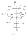
- FIG. 7 There is an adhesive bandage in the form shown in Fig. 7 as a conventional adhesive bandage for application to a fingertip of hand or foot.
- Fig. 7 is a plane view of the conventional adhesive bandage 120 for application to a fingertip.
- Figs. 8(a) to (c) and Figs. 9(a) to (c) are drawings for illustrating a method of applying the conventional adhesive bandage 120 to a fingertip of hand
- Fig. 8 is plane views viewing from a nail-side of the fingertip
- the conventional adhesive bandage 120 will be explained hereafter while referring to Figs. 7 to 9.
- a fiber fabric 103 is shown in a way of pointillism for the sake of illustration.
- conventional adhesive bandage 120 for use in fingertip is formed in an approximate-T shape as a whole, and which is made up of a backing sheet consisting of a fiber fabric 103 (see Fig. 8 and Fig. 9) and a film 101 laminating said fiber fabric 103, an adhesive layer (not shown) formed on a surface of the backing sheet on which said fiber fabric 103 is set, and a pad 102 set on said adhesive layer (not shown) which is attached to an affected part.
- Said adhesive bandage 120 may have release papers covering an adhesive surface, a backing sheet surface of adhesive-layer side (not shown). With regard to said release papers, only a release paper 119b covering second adhesive portion 117 is shown in Fig. 9(a).
- Said adhesive bandage 120 has a first adhesive portion 115 adhered to the nail-side of a finger and a second adhesive portion 117 adhered to the finger-cushion side opposite to said first adhesive portion by being folded from the nail-side of the finger, and the adhesive bandage can be folded at the folding area 116 which is a boundary between said first adhesive portion 115 and said adhesive portion 117.
- the pad 102 lies across the folding area 116.
- the adhesive bandage 120 is shaped symmetrically against the hypothetical center line Y-Y in a direction perpendicular to the long direction of the folding area 116.
- Said first adhesive portion 115 is formed in a rectangular shape having a long side in a direction toward the fingertip adhered, that is, a direction perpendicular to the folding area 116.
- said second adhesive portion 117 is approximate-rectangular shape having its long side in the direction parallel to the folding area 116, projecting by the same lengths from the hypothetical center line Y-Y to both directions parallel to said folding area 116, and the portions longer than the folding area form the projection portions 117a.
- An angle X formed between the first adhesive portion 115 and the second adhesive portion 117 outside the adhesive bandage 120 is obtuse angle.
- the conventional adhesive bandage 120 is attached to the affected part of the fingertip of hand or foot.
- FIG. 10 shows a plane view of the conventional adhesive bandage 130
- Figs. 11(a) to (c) show a method of adhering the conventional adhesive bandage 130 to a fingertip, which are plane views viewing from nail side.
- the conventional adhesive bandage 130 is formed in approximate-8-figure shape as a whole and comprised of a film 121 as a backing sheet, an adhesive layer (not shown) formed on a side of said backing sheet and a pad 122 set on said adhesive layer (not shown) which is attached to an affected part.
- the adhesive bandage 130 has a release paper covering the adhesive layer surface, that is, a backing sheet surface of the adhesive-layer side, and said film 12 1 has air holes 121a.
- the release paper only a release paper 129b is shown in Fig. 11(a) covering the second adhesive portion 127 described below.
- Said adhesive bandage 130 has a first adhesive portion 125 adhered to a finger cushion of a fingertip of hand or foot, for example, and a second adhesive portion 127 folded from the finger-cushion side and adhered to the nail-side of the fingertip opposite to said first adhesive portion 125, and can be folded at the folding area 126, which is a boundary between the first adhesive portion 125 and the second adhesive portion 127.
- the first adhesive portion 125 and the second adhesive portion 127 is formed in the same shape with each other, and the shape of the adhesive bandage 130 is symmetric with respect to the folding area 126 and to the hypothetical center line Y-Y perpendicular to the folding area 126.
- the pad 122 also lies across the folding area 126.
- the first adhesive portion 125 and the second adhesive portion 127 are approximate-trapeziforms of which peripheries are formed of a curved lines, and said folding area 126 corresponding to an upper side is a short side. That is, a long side corresponding to a lower side projects from the hypothetical center line Y-Y toward the both directions parallel to the folding area 126 by the same lengths.
- the wider portions than the folding area form the first projecting portions 125a and the second projecting portions 127a.
- the conventional adhesive bandage 130 is adhered to the fingertip so that the pad 122 is attached to an affected part of the fingertip of hand or foot.
- the adhesive bandage 130 is easy to conform to the shape of the fingertip and to envelop the fingertip.
- the conventional adhesive bandages 120 and 130 are required improvements regarding following points.
- the angle X formed between the first adhesive portion 115 and the second adhesive portion 117 outside the adhesive bandage 120 is large, and when adhered to a fingertip, there is a problem such that a clearance gap is apt to be formed near edge portion 116a of the folding area 116. Thus a problem will arise such that water gets in from the clearance gap so that the pad gets wet during such as bathing or washing.
- the conventional adhesive bandage 120 is difficult to fit to the curved surface of the fingertip and apt to decrease adherence between the pad 102 and the affected part.
- the angle X which is formed by peripheral curves of the first adhesive portion 125 and the second adhesive portion outside the adhesive bandage 130 becomes comparatively large. Therefore when it is adhered to a fingertip, a clearance gap is apt to be formed near edge portion 126a of the folding area 126, and water intrudes from the clearance gap so that the pad 122 gets wet with the water.
- This invention aims to solve above-said problems and to provide bandage which tightly envelops an affected part of a fingertip of hand or foot to prevent intrusion of such as water and bacteria, in particular an adhesive bandage formed of the bandage and a pad.
- An adhesive bandage of the present invention is an adhesive bandage having a backing sheet and an adhesive layer on one side of said backing sheet characterized in that: said adhesive bandage is comprised of a first adhesive portion which is adhered to a finger-cushion surface of fingertip, and a second adhesive portion which is folded from said finger-coshion side to be adhered to a nail-side surface of the fingertip so as to face the first adhesive portion across the fingertip; said first adhesive portion has first projecting portions which are folded from the finger-cushion side and adhered to each side surface of the fingertip; said second adhesive portion has second projecting portions and third projecting portions folded from the nail-side toward the finger-cushion side and wound around the fingertip; and said fingertip is enveloped in the first adhesive portion and the second adhesive portion.
- the adhesive bandage of the present invention can be that having folding area on the border between said first adhesive portion and said second adhesive portion, and a shape of said adhesive bandage is symmetrical with respect to a hypothetical center line in the direction perpendicular to said folding area.
- the second projecting portions and the projecting portions of the adhesive bandage of the present invention can be constructed to extend in the direction parallel to the folding area, and second projecting portions and said first adhesive portion adjoin across said folding area.
- the second projecting portions and the third projecting portions of the adhesive bandage of the present invention can be placed separately in the direction perpendicular to said folding area, said second projecting portion Vietnamese has a straight line approximately parallel to said folding area, and said third projecting portion has approximately rectangular shape.
- the length of said first projecting portion in the direction parallel to said folding area of the adhesive bandage according to the present invention can be shorter than tbat of the second projecting portion and the third projecting portion, and the periphery of the first projecting portion is formed of curved-line.
- the length of said third projecting portion in the direction parallel to the folding area of the adhesive bandage according to the present invention can be longer than that of said second projecting portion.
- the adhesive bandage of the present invention may have a pad lying across the folding area.
- the adhesive bandage according to the present invention may have release papers covering the surface of said adhesive layer.
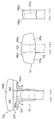
- Fig. 1 is a plan view of an adhesive bandage of the present invention.
- Fig. 2 (a) is a plan view illustrating an adhesive-layer side of the adhesive bandage of this invention.
- Fig. 2 (b) is a plan view illustrating a state covering the adhesive-layer surface with a release paper in Fig. 2 (a).
- Fig. 3 illustrates schematically A-A section of the Fig. 1. The adhesive bandage 1 of this invention will be explained referring Fig. 1 to 3.
- the adhesive bandage 1 is composed of a backing sheet comprising a thermoplastic fiber fabric 12 (shown in Fig. 2(a)) and a film 2 laminating the thermoplastic fiber fabric 12, an adhesive layer 14 (illustrated in Fig. 3) formed on the thermoplastic-fiber-fabric 12 side surface of the backing sheet, and a pad 3 set on the adhesive layer surface 14 and which will be attached to an affected part.
- the adhesive bandage has a release paper 9a and a release paper 9b covering the adhesive surface, that is, the adhesive-layer-side surface of the backing sheet. Said release paper 9a is set so as to cover the first adhesive portion 5 described below, and said release paper 9b, the second adhesive portion described below.
- said thermoplastic fiber fabric 12 is illustrated in a way of pointillism for illustration purpose.
- the adhesive bandage 1 described above has a first adhesive portion 5 which is adhered to finger cushion of a fingertip of hand or foot and a second adhesive portion 7 which is folded from said finger-cushion side, adhered to a nail-side surface of the fingertip so as to face the first adhesive portion 5 across the fingertip, and said first adhesive portion 5 and said second adhesive portion 7 may be folded at the folding area 6. That is, said first adhesive portion 5 and said second adhesive portion 7 are integrally formed and it is folded at the folding area and adhered to the fingertip. Said pad 3 is lying across the folding area and the adhesive bandage 1 is formed in a shape symmetrical with respect to a hypothetical center line B-B in the direction perpendicular to the folding area.
- the periphery of the first adhesive portion 5 is formed in approximate circular curve, and has the first projecting portions 5a projecting toward the both directions parallel to the folding area from said hypothetical center line B-B.
- the maximum radius, the length of said first projecting portion 5a from the hypothetical center line B-B, is L1.
- the second adhesive portion 7 is formed projecting toward the both directions parallel to the folding area 6 from said hypothetical center line B-B, and has second projecting portions 7a and third projecting portions 7b separately arranged in the direction perpendicular to said folding area
- the periphery of the third projecting portion 7b toward 2a overlaps the periphery of the first projecting portion 5a in about the constant width so that intrusion of water may be avoided.
- Said second projecting portions 7a adjoin the first adhesive portion 5 across the folding area 6, project from said hypothetical center line B-B by the length of L2 respectively, have an straight-line section 17a nearly parallel to the folding area 6, and periphery of the tip area 17b is curved
- the third projecting portions 7b project from said hypothetical center line B-B by the length of L3 respectively, have a rectangular-like shape periphery. That is, two third projecting portions must have enough length so that the tips of the projecting portion may wind around the finger from respective directions and may overlap with each other when this adhesive bandage is applied, and thereby intrusion of water from the palm direction may be avoided.
- the gap X formed by the first adhesive portion 5 and the second projecting portion 7 outside the adhesive bandage 1 is narrow at acute angle because the periphery of the first adhesive portion 5 is curved and has the first projecting portion and the second projecting portion 7 has a straight-line section 17a approximately parallel to the folding area 6.
- the lengths of the first projecting portion 5a, the second projection portion 7a and the third projecting portion 7b from the hypothetical center line B-B, L1, L2 and L3 respectively, have the relation shown by the following formula (1): L3>L2>L1.
- the length of the third projecting portion 7b is the largest of all, then the second projecting portion 7a and then the first projecting portion 5a.
- the thermoplastic fiber fabric 12 preferably has a high gas permeability and elasticity and includes woven fabrics and nonwoven fabrics made of thermoplastic elastomers.
- the thermoplastic elastomer can be, for example, polystyrene-type elastomers such as styrene-isoprene-styrene type block copolymer and hydrogenated block copolymers hydrogenating said block copolymer, polyurethanes, polyesters and polyolefines such as polyethylene, they are, however, not critical and other material may be selected.
- the fabric of the present invention can be either a woven fabric or a nonwoven fabric, but the nonwoven fabric is preferred because the directional dependency of physical properties such as elasticity is low.
- the percentage expansion of the nonwoven fabric is preferably 100% or more, a recovery rate in expansion is 70 % or more.
- the weight of the nonwoven fabric of this invention has to be properly selected depending on properties of the nonwoven fabric itself, the laminating film and the adhesive, but cannot particularly be limited. However, the weight is preferably 20 to 200 g/m 2 , more preferably 30 to 100 g/m 2 .
- a thickness of the nonwoven fabric may be such that a sufficient stiffness is imparted to the backing sheet of the adhesive bandage when laminating a film on the nonwoven fabric.
- the thickness of the nonwoven fabric is about 20 to 1,000 ⁇ m, preferably 50 to 500 ⁇ m.
- the film 2 is used to impart water proofing property to the adhesive bandage 1 without much decrease in gas permeability and water vapor permeability of the thermoplastic fiber fabric 12 as well as to ensure a suitable balance of properties when an adhesive bandage is made.
- the material of the film is required to have a water proofing property and to have sufficient water vapor permeability even after laminated on a thermoplastic fiber fabric 12. That is, the water vapor can permeate the film and liquid water cannot permeate, and as such films, known films made of polyurethanes, polyvinyl chloride, polyvinylidene chloride, polyolefines such as polyethylene and polypropylene, polyesters, polyamides and so forth can be used. Polyurethane films and polyester films in particular are preferred among them because they have high water vapor permeability and appropriate flexitility.
- polyester elastomer for example, polyester elastomer "Hytrel” (Trademark of E. I. DU PONT DE NEMOURS AND COMPANY), "Fleclone”(Trademark of Nichigo Film Kabushiki Kaisha) and so forth are preferred. Since the laminating film 2 must have a sufficient water proofing property, a film made by extrusion molding, blow-molding or the like is desirous. A drawn film is also available. Said laminating film can be also a multilayered film formed by laminating films made of different materials.
- the film 2 has to be thin in order to have a high water vapor permeability. If the material of the laminating film has high water vapor permeability, it can be thick, but has to have suitable stiffness wLen laminated on the fiber fabric. From this standpoint, the thickness of said film is preferably 50 ⁇ m or less, more preferably 2 to 30 ⁇ m, and further more preferably 5 to 15 ⁇ m.
- the adhesive used in the adhesive bandage of the present invention is not particularly limited as far as the skin is little irritated and pressure-sensitive adhesion to skin is provided.
- the adhesive include rubbery adhesives, acrylic adhesives, polyurethane adhesives, silicone adhesives and A-B-A type block copolymer type adhesives such as styrene-isoprene-styrene block copolymer type adhesives, etc.
- the thickness of the adhesive layer 14 is 25 to 150 ⁇ m, preferably 30 to 60 ⁇ m.
- the adhesive layer 14 can be formed by flat coating in which the adhesive is coated on the whole surface of the backing sheet composed of the film 2 and the thermoplastic fiber fabric 12, however coating a porous adhesive or pattern coating is preferred in order to ensure high water vapor permeability of the adhesive layer.
- the adhesive porous there is, for example, a method in which a highly water-absorbable polymer is used as a blowing agent, which fully absorbs water, the resulting polymer is dispersed into an adhesive solution, the dispersion is coated, and a moisture is then evaporated to make the adhesive porous.
- a highly water-absorbable polymer is used as a blowing agent, which fully absorbs water, the resulting polymer is dispersed into an adhesive solution, the dispersion is coated, and a moisture is then evaporated to make the adhesive porous.
- the adhesive can be coated on the backing sheet by, for example, screen coating or gravure coating.
- a method of coating the adhesive on the backing sheet there can be taken various known methods such as a method in which the backing sheet is directly coated with the adhesive, a method in which a release paper is coated with the adhesive and then the adhesive is transferred onto the backing sheet, and the like.
- the film 2 and thermoplastic fiber fabric 12 are laminated in the state all the periphery is heat-sealed in a constant width, in this case, about 1.5 mm width.
- the laminating method is not particularly restricted, and a method of heat-melting, a method using an adhesive can be adopted.
- the laminate can be performed either before forming the adhesive layer 14 or after forming the adhesive layer 14 on the backing sheet.
- the heat-sealed section 2a formed by heat-sealing near the periphery of the film 2 and the thermoplastic fiber fabric 12 is formed on the whole periphery thereof and has a certain width, in this Example, about 1.5mm.
- the width of the heat-sealed section 2a is not particularly limited, 0.5 ⁇ 4mm is preferred, and 1 ⁇ 2mm is particularly preferred.
- Methods of heat-seal can be that of pressing a subject sheet with a flat face maintaining a predetermined temperature, tbat of pressing a sheet with such as a rotary press, etc., the method is, however, not critical.
- the flat seal can be used for the heat-seal, and also the pattern seal can be adopted.
- the pattern seal refers to a heat-seal method tbat does not seal the whole surface of the sealing area but unsealed surface is remained in the sealing area.
- the pattern seal provides the sealing area 2a with a higher gas permeability and a water vapor permeability since the unsealed surface has higher gas permeability and water vapor permeability than the sealed surface.
- the peripheral end of the backing sheet constructed by laminating the thermoplastic fiber fabric 12 and the film 2 is sealed by the heat-scaled section 2a, and the outside environment and the pad 3 are perfectly isolated. Therefore the adhesive bandage 1 can prevent intrusion of water from outside.
- thermoplastic fiber fabric 12 When using a material of the film 2 having higher melting point than the thermoplastic fiber fabric 12 and setting the heat-sealing temperature lower than the melting point of the film 2 and higher than the melting point of the thermoplastic fiber fabric, only the fiber fabric melts and the heat-sealed section can be formed in the same process as the cutting process of the backing sheet. In such process, the film 2 and the thermoplastic fiber fabric 12 is formed in the same size, and positioning between the film 2 and the thermoplastic fiber fabric 12 is avoided.
- the condition is satisfied.
- the fiber fabric 12 melts when heat-sealing is performed at temperatures near the melting point of the film.
- FIG. 4 includes plane views viewing from nail-side of the fingertip
- Fig. 5 includes plane views viewing from finger-cushion-side of the fingertip.
- the thermoplastic fiber fabric is illustrated in a way of pointillism for illustration purpose.
- the adhesive bandage 1 is adhered to a fingertip of a hand or foot.
- the gap X formed by the first adhesive portion 5 of which periphery is formed of curved line and the second adhesive portion 7 having the straight line section 17a approximately parallel to the folding area 6 outside the adhesive bandage 1 is small.
- the adhesive bandage 1 is applied to a fingertip, the gap is hardly formed near the end section 6a of the folding area 6. That is, the adhesive bandage 1 is seal from the outside environment by envelopping the fingertip with the first adhesive portion 5 and second adhesive portion 7, thereby intrusion of water, bacteria, etc. is prevented.
- the adhesive bandage 1 since the first adhesive portion 5 and the second adhesive portion 7 are formed large comparing to a fingertip, respective lengths in the direction parallel to the folding area 6 are arranged in order of the third projecting portion 7b the longest, the second projecting portion 7a, and the first projecting portion 5a the shortest, it is easy to fit with curved surface of fingertip and can firmly envelop the fingertip.
- the pad 3 lies across the folding area, the pad 3 can be firmly attachod to an affected part of the fingertip enveloped by the first adhesive portion 5 and the second adhesive portion 7.
- the shapes of adhesive bandages of the present invention are not limited to these Examples, and can be, for example, Fig. 6(a) to (f).
- Fig. 6(a) to (f) each folding area which is a boundary between the first adhesive portion and the second adhesive portion is shown by two dotted dashed line.
- the Fig. (e) to (f) is drawings having projecting portion further projecting from the first projecting portion of the first adhesive portion. Further the other shapes can be adopted to the present invention as far as satisfying essential conditions of the present invention.
- the backing sheet is composed of thermoplastic fiber fabric and thermoplastic film;
- the adhesive bandage can be formed of thermoplastic fiber fabric;
- the thermoplastic fiber fabric is styrene-isoprene-styrene type block copolymer;
- the thermoplastic film is polyurethane film;
- the adhesive is porous; the whole periphery of the backing sheet is sealed.
- the adhesive bandage of the present invention can firmly envelop an affected part of a fingertip of hand or foot, and prevent intrusion of water, bacteria, etc. through a gap which may be formed during application or decrease in adhesion properties between the pad and the affected part if an adhesive bandage having a pad is applied.
Landscapes
- Health & Medical Sciences (AREA)
- Dermatology (AREA)
- Engineering & Computer Science (AREA)
- Biomedical Technology (AREA)
- Heart & Thoracic Surgery (AREA)
- Vascular Medicine (AREA)
- Life Sciences & Earth Sciences (AREA)
- Animal Behavior & Ethology (AREA)
- General Health & Medical Sciences (AREA)
- Public Health (AREA)
- Veterinary Medicine (AREA)
- Materials For Medical Uses (AREA)
- Medicinal Preparation (AREA)
Applications Claiming Priority (2)
| Application Number | Priority Date | Filing Date | Title |
|---|---|---|---|
| JP34919798 | 1998-12-08 | ||
| JP34919798 | 1998-12-08 |
Publications (2)
| Publication Number | Publication Date |
|---|---|
| EP1008330A2 true EP1008330A2 (de) | 2000-06-14 |
| EP1008330A3 EP1008330A3 (de) | 2001-05-30 |
Family
ID=18402136
Family Applications (1)
| Application Number | Title | Priority Date | Filing Date |
|---|---|---|---|
| EP99124010A Withdrawn EP1008330A3 (de) | 1998-12-08 | 1999-12-08 | Selbstklebender Wundverband |
Country Status (9)
| Country | Link |
|---|---|
| EP (1) | EP1008330A3 (de) |
| JP (1) | JP4514956B2 (de) |
| CN (1) | CN1258485A (de) |
| AU (2) | AU1680800A (de) |
| BR (1) | BR9907411A (de) |
| CA (1) | CA2291923A1 (de) |
| NZ (1) | NZ501489A (de) |
| WO (1) | WO2000033777A1 (de) |
| ZA (1) | ZA997502B (de) |
Cited By (11)
| Publication number | Priority date | Publication date | Assignee | Title |
|---|---|---|---|---|
| US6897348B2 (en) | 2001-12-19 | 2005-05-24 | Kimberly Clark Worldwide, Inc | Bandage, methods of producing and using same |
| US6967261B1 (en) | 2001-12-28 | 2005-11-22 | Kimberly-Clark Worldwide | Bandage, methods of producing and using same |
| US7091394B2 (en) | 2000-11-20 | 2006-08-15 | Coloplast A/S | Dressing |
| WO2010012824A1 (en) * | 2008-08-01 | 2010-02-04 | Pierre Fabre Dermo-Cosmetique | Kit for the treatment of onychomycosis |
| USD723175S1 (en) | 2014-05-05 | 2015-02-24 | Coloplast A/S | Wound dressing |
| USD723176S1 (en) | 2014-05-05 | 2015-02-24 | Coloplast A/S | Wound dressing |
| USD723177S1 (en) | 2014-05-05 | 2015-02-24 | Coloplast A/S | Wound dressing |
| USD723702S1 (en) | 2014-06-03 | 2015-03-03 | Coloplast A/S | Wound dressing |
| USD729391S1 (en) | 2014-05-05 | 2015-05-12 | Coloplast A/S | Wound dressing |
| USD952163S1 (en) | 2021-02-09 | 2022-05-17 | Coloplast A/S | Wound dressing |
| USD962449S1 (en) | 2021-02-09 | 2022-08-30 | Coloplast A/S | Wound dressing |
Families Citing this family (2)
| Publication number | Priority date | Publication date | Assignee | Title |
|---|---|---|---|---|
| KR200487591Y1 (ko) * | 2018-06-14 | 2018-10-11 | (주)아텍스 | 부착성이 개선된 일회용 밴드 |
| MY210099A (en) | 2019-02-27 | 2025-08-27 | Woolaid Ltd | Breathable adhesive bandages |
Family Cites Families (11)
| Publication number | Priority date | Publication date | Assignee | Title |
|---|---|---|---|---|
| BE524281A (de) * | ||||
| GB704214A (en) * | 1951-01-08 | 1954-02-17 | Ruprecht Weisse | Adhesive bandage |
| US3529597A (en) * | 1968-04-19 | 1970-09-22 | George T Fuzak | Fingertip bandage |
| US3547120A (en) * | 1968-05-27 | 1970-12-15 | Geraldine A Grossman | Bandages |
| JPS4737420Y1 (de) * | 1971-03-18 | 1972-11-13 | ||
| JPS4737420U (de) * | 1971-05-14 | 1972-12-25 | ||
| JPS60124923U (ja) * | 1984-01-31 | 1985-08-23 | ニチバン株式会社 | ばんそうこう |
| JPH0454962A (ja) * | 1990-06-25 | 1992-02-21 | Toyo Seal Kk | 指保護テープ |
| JP3259861B2 (ja) * | 1992-08-31 | 2002-02-25 | ジャサイ・ゾルタン・カズマー | 緩衝保護装置 |
| JP2603623Y2 (ja) * | 1993-03-20 | 2000-03-15 | タックシステム株式会社 | 防水指先救急絆創膏 |
| GB9623367D0 (en) * | 1996-11-09 | 1997-01-08 | Burke Michael A | Adhesive skin protector |
-
1999
- 1999-12-02 NZ NZ501489A patent/NZ501489A/en not_active IP Right Cessation
- 1999-12-06 ZA ZA9907502A patent/ZA997502B/xx unknown
- 1999-12-07 CA CA002291923A patent/CA2291923A1/en not_active Abandoned
- 1999-12-08 CN CN99126140A patent/CN1258485A/zh active Pending
- 1999-12-08 WO PCT/JP1999/006862 patent/WO2000033777A1/ja not_active Ceased
- 1999-12-08 EP EP99124010A patent/EP1008330A3/de not_active Withdrawn
- 1999-12-08 AU AU16808/00A patent/AU1680800A/en not_active Abandoned
- 1999-12-08 JP JP2000586272A patent/JP4514956B2/ja not_active Expired - Lifetime
- 1999-12-08 AU AU64419/99A patent/AU6441999A/en not_active Abandoned
- 1999-12-08 BR BR9907411-7A patent/BR9907411A/pt not_active IP Right Cessation
Cited By (16)
| Publication number | Priority date | Publication date | Assignee | Title |
|---|---|---|---|---|
| US7091394B2 (en) | 2000-11-20 | 2006-08-15 | Coloplast A/S | Dressing |
| US6897348B2 (en) | 2001-12-19 | 2005-05-24 | Kimberly Clark Worldwide, Inc | Bandage, methods of producing and using same |
| US6967261B1 (en) | 2001-12-28 | 2005-11-22 | Kimberly-Clark Worldwide | Bandage, methods of producing and using same |
| WO2010012824A1 (en) * | 2008-08-01 | 2010-02-04 | Pierre Fabre Dermo-Cosmetique | Kit for the treatment of onychomycosis |
| FR2934782A1 (fr) * | 2008-08-01 | 2010-02-12 | Fabre Pierre Dermo Cosmetique | Kit pour le traitement des onychomycoses. |
| AU2009275865B2 (en) * | 2008-08-01 | 2013-11-21 | Pierre Fabre Dermo-Cosmetique | Kit for the treatment of onychomycosis |
| USD723177S1 (en) | 2014-05-05 | 2015-02-24 | Coloplast A/S | Wound dressing |
| USD723176S1 (en) | 2014-05-05 | 2015-02-24 | Coloplast A/S | Wound dressing |
| USD723175S1 (en) | 2014-05-05 | 2015-02-24 | Coloplast A/S | Wound dressing |
| USD723704S1 (en) | 2014-05-05 | 2015-03-03 | Coloplast A/S | Wound dressing |
| USD723703S1 (en) | 2014-05-05 | 2015-03-03 | Coloplast A/S | Wound dressing |
| USD729391S1 (en) | 2014-05-05 | 2015-05-12 | Coloplast A/S | Wound dressing |
| USD729392S1 (en) | 2014-05-05 | 2015-05-12 | Coloplast A/S | Wound dressing |
| USD723702S1 (en) | 2014-06-03 | 2015-03-03 | Coloplast A/S | Wound dressing |
| USD952163S1 (en) | 2021-02-09 | 2022-05-17 | Coloplast A/S | Wound dressing |
| USD962449S1 (en) | 2021-02-09 | 2022-08-30 | Coloplast A/S | Wound dressing |
Also Published As
| Publication number | Publication date |
|---|---|
| BR9907411A (pt) | 2001-01-16 |
| CN1258485A (zh) | 2000-07-05 |
| ZA997502B (en) | 2001-06-06 |
| WO2000033777A1 (en) | 2000-06-15 |
| AU6441999A (en) | 2000-06-15 |
| JP4514956B2 (ja) | 2010-07-28 |
| NZ501489A (en) | 2001-08-31 |
| CA2291923A1 (en) | 2000-06-08 |
| AU1680800A (en) | 2000-06-26 |
| EP1008330A3 (de) | 2001-05-30 |
Similar Documents
| Publication | Publication Date | Title |
|---|---|---|
| US5928972A (en) | Method of heat-sealing adhesive bandage and adhesive bandage made by using said method | |
| EP1008330A2 (de) | Selbstklebender Wundverband | |
| US5736470A (en) | Pressure sensitive adhesive article and method of making | |
| FI79939C (fi) | Pao huden laett applicebart haeftfoerband. | |
| US7563941B2 (en) | Modular wound dressing system | |
| US5531855A (en) | Carrier delivered dressing and method of manufacture | |
| WO1999007316A1 (en) | Self adhesive bandage roll | |
| EP0921775A1 (de) | Medizinische klebende zusammensetzung und verpackung | |
| SK283267B6 (sk) | Vonkajšia náplasť a spôsob jej výroby | |
| EP2044910A1 (de) | Heizdecke und Heizdeckentasche | |
| CA1324352C (en) | Primary pack for surface-stabilized bandaging materials | |
| JPWO2000033777A1 (ja) | 絆創膏 | |
| MXPA99011483A (es) | Almohadilla, metodo de produccion para la misma y vendaje adhesivo con el uso de dicha almohadilla. | |
| JP2004051516A (ja) | シート状パック | |
| JPH10500585A (ja) | 医療用バンド体並びにパッキングシステム | |
| AU2004202882A1 (en) | Adhesive bandage | |
| US20050102786A1 (en) | Lotion applicator | |
| JPS61126018A (ja) | 貼付材等用支持体 | |
| JP4750321B2 (ja) | 絆創膏 | |
| JP2004216098A (ja) | 貼付シートまたはテープ | |
| AU780014B2 (en) | Method of heat sealing adhesive bandage and adhesive bandage made by using said method | |
| JP3737871B2 (ja) | 四肢誘導電極用パッド | |
| JP3970639B2 (ja) | 貼着体 | |
| JPH0124882B2 (de) | ||
| JPH072581Y2 (ja) | 治療用貼着シート |
Legal Events
| Date | Code | Title | Description |
|---|---|---|---|
| PUAI | Public reference made under article 153(3) epc to a published international application that has entered the european phase |
Free format text: ORIGINAL CODE: 0009012 |
|
| AK | Designated contracting states |
Kind code of ref document: A2 Designated state(s): AT BE CH CY DE DK ES FI FR GB GR IE IT LI LU MC NL PT SE |
|
| AX | Request for extension of the european patent |
Free format text: AL;LT;LV;MK;RO;SI |
|
| PUAL | Search report despatched |
Free format text: ORIGINAL CODE: 0009013 |
|
| AK | Designated contracting states |
Kind code of ref document: A3 Designated state(s): AT BE CH CY DE DK ES FI FR GB GR IE IT LI LU MC NL PT SE |
|
| AX | Request for extension of the european patent |
Free format text: AL;LT;LV;MK;RO;SI |
|
| RIC1 | Information provided on ipc code assigned before grant |
Free format text: 7A 61F 13/02 A, 7A 61F 13/10 B |
|
| 17P | Request for examination filed |
Effective date: 20011130 |
|
| AKX | Designation fees paid |
Free format text: AT BE CH CY DE DK ES FI FR GB GR IE IT LI LU MC NL PT SE |
|
| 17Q | First examination report despatched |
Effective date: 20030108 |
|
| STAA | Information on the status of an ep patent application or granted ep patent |
Free format text: STATUS: THE APPLICATION IS DEEMED TO BE WITHDRAWN |
|
| 18D | Application deemed to be withdrawn |
Effective date: 20030520 |