EP1008408A2 - Outil de coupe type ajustement serré - Google Patents
Outil de coupe type ajustement serré Download PDFInfo
- Publication number
- EP1008408A2 EP1008408A2 EP99123277A EP99123277A EP1008408A2 EP 1008408 A2 EP1008408 A2 EP 1008408A2 EP 99123277 A EP99123277 A EP 99123277A EP 99123277 A EP99123277 A EP 99123277A EP 1008408 A2 EP1008408 A2 EP 1008408A2
- Authority
- EP
- European Patent Office
- Prior art keywords
- shaft portion
- hole portion
- peripheral surface
- section
- cutting tool
- Prior art date
- Legal status (The legal status is an assumption and is not a legal conclusion. Google has not performed a legal analysis and makes no representation as to the accuracy of the status listed.)
- Withdrawn
Links
Images






Classifications
-
- B—PERFORMING OPERATIONS; TRANSPORTING
- B23—MACHINE TOOLS; METAL-WORKING NOT OTHERWISE PROVIDED FOR
- B23B—TURNING; BORING
- B23B27/00—Tools for turning or boring machines; Tools of a similar kind in general; Accessories therefor
- B23B27/007—Tools for turning or boring machines; Tools of a similar kind in general; Accessories therefor for internal turning
-
- B—PERFORMING OPERATIONS; TRANSPORTING
- B23—MACHINE TOOLS; METAL-WORKING NOT OTHERWISE PROVIDED FOR
- B23B—TURNING; BORING
- B23B31/00—Chucks; Expansion mandrels; Adaptations thereof for remote control
- B23B31/005—Cylindrical shanks of tools
-
- B—PERFORMING OPERATIONS; TRANSPORTING
- B23—MACHINE TOOLS; METAL-WORKING NOT OTHERWISE PROVIDED FOR
- B23B—TURNING; BORING
- B23B2231/00—Details of chucks, toolholder shanks or tool shanks
- B23B2231/02—Features of shanks of tools not relating to the operation performed by the tool
- B23B2231/0204—Connection of shanks to working elements of tools
-
- B—PERFORMING OPERATIONS; TRANSPORTING
- B23—MACHINE TOOLS; METAL-WORKING NOT OTHERWISE PROVIDED FOR
- B23B—TURNING; BORING
- B23B2240/00—Details of connections of tools or workpieces
- B23B2240/28—Shrink-fitted connections, i.e. using heating and cooling to produce interference fits
-
- Y—GENERAL TAGGING OF NEW TECHNOLOGICAL DEVELOPMENTS; GENERAL TAGGING OF CROSS-SECTIONAL TECHNOLOGIES SPANNING OVER SEVERAL SECTIONS OF THE IPC; TECHNICAL SUBJECTS COVERED BY FORMER USPC CROSS-REFERENCE ART COLLECTIONS [XRACs] AND DIGESTS
- Y10—TECHNICAL SUBJECTS COVERED BY FORMER USPC
- Y10T—TECHNICAL SUBJECTS COVERED BY FORMER US CLASSIFICATION
- Y10T279/00—Chucks or sockets
- Y10T279/17—Socket type
- Y10T279/17957—Friction grip
-
- Y—GENERAL TAGGING OF NEW TECHNOLOGICAL DEVELOPMENTS; GENERAL TAGGING OF CROSS-SECTIONAL TECHNOLOGIES SPANNING OVER SEVERAL SECTIONS OF THE IPC; TECHNICAL SUBJECTS COVERED BY FORMER USPC CROSS-REFERENCE ART COLLECTIONS [XRACs] AND DIGESTS
- Y10—TECHNICAL SUBJECTS COVERED BY FORMER USPC
- Y10T—TECHNICAL SUBJECTS COVERED BY FORMER US CLASSIFICATION
- Y10T279/00—Chucks or sockets
- Y10T279/17—Socket type
- Y10T279/17957—Friction grip
- Y10T279/17965—Drill type
-
- Y—GENERAL TAGGING OF NEW TECHNOLOGICAL DEVELOPMENTS; GENERAL TAGGING OF CROSS-SECTIONAL TECHNOLOGIES SPANNING OVER SEVERAL SECTIONS OF THE IPC; TECHNICAL SUBJECTS COVERED BY FORMER USPC CROSS-REFERENCE ART COLLECTIONS [XRACs] AND DIGESTS
- Y10—TECHNICAL SUBJECTS COVERED BY FORMER USPC
- Y10T—TECHNICAL SUBJECTS COVERED BY FORMER US CLASSIFICATION
- Y10T29/00—Metal working
- Y10T29/49—Method of mechanical manufacture
- Y10T29/49826—Assembling or joining
- Y10T29/49863—Assembling or joining with prestressing of part
- Y10T29/49865—Assembling or joining with prestressing of part by temperature differential [e.g., shrink fit]
-
- Y—GENERAL TAGGING OF NEW TECHNOLOGICAL DEVELOPMENTS; GENERAL TAGGING OF CROSS-SECTIONAL TECHNOLOGIES SPANNING OVER SEVERAL SECTIONS OF THE IPC; TECHNICAL SUBJECTS COVERED BY FORMER USPC CROSS-REFERENCE ART COLLECTIONS [XRACs] AND DIGESTS
- Y10—TECHNICAL SUBJECTS COVERED BY FORMER USPC
- Y10T—TECHNICAL SUBJECTS COVERED BY FORMER US CLASSIFICATION
- Y10T403/00—Joints and connections
- Y10T403/21—Utilizing thermal characteristic, e.g., expansion or contraction, etc.
- Y10T403/217—Members having different coefficients of expansion
-
- Y—GENERAL TAGGING OF NEW TECHNOLOGICAL DEVELOPMENTS; GENERAL TAGGING OF CROSS-SECTIONAL TECHNOLOGIES SPANNING OVER SEVERAL SECTIONS OF THE IPC; TECHNICAL SUBJECTS COVERED BY FORMER USPC CROSS-REFERENCE ART COLLECTIONS [XRACs] AND DIGESTS
- Y10—TECHNICAL SUBJECTS COVERED BY FORMER USPC
- Y10T—TECHNICAL SUBJECTS COVERED BY FORMER US CLASSIFICATION
- Y10T403/00—Joints and connections
- Y10T403/48—Shrunk fit
-
- Y—GENERAL TAGGING OF NEW TECHNOLOGICAL DEVELOPMENTS; GENERAL TAGGING OF CROSS-SECTIONAL TECHNOLOGIES SPANNING OVER SEVERAL SECTIONS OF THE IPC; TECHNICAL SUBJECTS COVERED BY FORMER USPC CROSS-REFERENCE ART COLLECTIONS [XRACs] AND DIGESTS
- Y10—TECHNICAL SUBJECTS COVERED BY FORMER USPC
- Y10T—TECHNICAL SUBJECTS COVERED BY FORMER US CLASSIFICATION
- Y10T403/00—Joints and connections
- Y10T403/66—Interfitted members with external bridging piece
-
- Y—GENERAL TAGGING OF NEW TECHNOLOGICAL DEVELOPMENTS; GENERAL TAGGING OF CROSS-SECTIONAL TECHNOLOGIES SPANNING OVER SEVERAL SECTIONS OF THE IPC; TECHNICAL SUBJECTS COVERED BY FORMER USPC CROSS-REFERENCE ART COLLECTIONS [XRACs] AND DIGESTS
- Y10—TECHNICAL SUBJECTS COVERED BY FORMER USPC
- Y10T—TECHNICAL SUBJECTS COVERED BY FORMER US CLASSIFICATION
- Y10T407/00—Cutters, for shaping
- Y10T407/19—Rotary cutting tool
- Y10T407/1906—Rotary cutting tool including holder [i.e., head] having seat for inserted tool
- Y10T407/1932—Rotary cutting tool including holder [i.e., head] having seat for inserted tool with means to fasten tool seat to holder
-
- Y—GENERAL TAGGING OF NEW TECHNOLOGICAL DEVELOPMENTS; GENERAL TAGGING OF CROSS-SECTIONAL TECHNOLOGIES SPANNING OVER SEVERAL SECTIONS OF THE IPC; TECHNICAL SUBJECTS COVERED BY FORMER USPC CROSS-REFERENCE ART COLLECTIONS [XRACs] AND DIGESTS
- Y10—TECHNICAL SUBJECTS COVERED BY FORMER USPC
- Y10T—TECHNICAL SUBJECTS COVERED BY FORMER US CLASSIFICATION
- Y10T407/00—Cutters, for shaping
- Y10T407/22—Cutters, for shaping including holder having seat for inserted tool
- Y10T407/227—Cutters, for shaping including holder having seat for inserted tool with separate means to fasten tool seat to holder
-
- Y—GENERAL TAGGING OF NEW TECHNOLOGICAL DEVELOPMENTS; GENERAL TAGGING OF CROSS-SECTIONAL TECHNOLOGIES SPANNING OVER SEVERAL SECTIONS OF THE IPC; TECHNICAL SUBJECTS COVERED BY FORMER USPC CROSS-REFERENCE ART COLLECTIONS [XRACs] AND DIGESTS
- Y10—TECHNICAL SUBJECTS COVERED BY FORMER USPC
- Y10T—TECHNICAL SUBJECTS COVERED BY FORMER US CLASSIFICATION
- Y10T409/00—Gear cutting, milling, or planing
- Y10T409/30—Milling
- Y10T409/30952—Milling with cutter holder
-
- Y—GENERAL TAGGING OF NEW TECHNOLOGICAL DEVELOPMENTS; GENERAL TAGGING OF CROSS-SECTIONAL TECHNOLOGIES SPANNING OVER SEVERAL SECTIONS OF THE IPC; TECHNICAL SUBJECTS COVERED BY FORMER USPC CROSS-REFERENCE ART COLLECTIONS [XRACs] AND DIGESTS
- Y10—TECHNICAL SUBJECTS COVERED BY FORMER USPC
- Y10T—TECHNICAL SUBJECTS COVERED BY FORMER US CLASSIFICATION
- Y10T82/00—Turning
- Y10T82/25—Lathe
- Y10T82/2585—Tool rest
Definitions
- the present invention relates to an interference fit type cutting tool in which a tool is detachably and replaceably mounted in a tool holding section.
- FIG. 18 A boring bar as an example of this type of conventional cutting tool is shown in Figs. 18 and 19.
- This boring bar 1 is formed by detachably fitting a head section 4 having a throwaway tip 3 on a shank section 2 held by a machining center or the like (not shown).
- the shank section 2 is made of, for example, expensive cemented carbide having high rigidity. Since the head section 4 is prone to wear and damage due to chip abrasion, it is made of inexpensive steel or the like, and it is detachable and replaceable.
- head sections having different types of cutting edges can be mounted.
- a projection 6a formed at the center of a leading end face 6 of the shank section 2 is prismatically shaped, and a hole portion 7a in a base end face 7 of the head section 4 is formed in the shape of a prismatic recess.
- the projection 6a is fitted into the hole portion 7a, so that the leading end face 6 and the base end face 7 are in contact with each other, and the peripheral portions thereof are brazed.
- the projection 6a is formed in a substantially cylindrical shape and is externally threaded
- the hole portion 7a is shaped like a substantially cylindrical recess and is internally threaded to be screwed on the external thread of the projection 6a, and the projection 6a and the hole portion 7a are fitted together.
- the projection 6a and the hole portion 7a are subjected to shrinkage fitting.
- an object of the present invention is to provide an interference fit type cutting tool that achieves high tool stiffness and increases tool life.
- Another object of the present invention is to provide an interference fit type cutting tool that achieves high tool fixing strength and allows high-precision working.
- a further object of the present invention is to provide an interference fit type cutting tool that reduces vibration and runout during cutting and allows high-precision working.
- an interference fit type cutting tool includes a shaft portion provided in one of a tool with a cutting edge and a tool holding section, and a hole portion provided in the other to be interference-fitted on the shaft portion, wherein the shaft portion and the hole portion have a taper portion and a tapered portion at least in a part thereof, and one of the taper portion and the tapered portion has an interference.
- the shaft portion and the hole portion are fixedly pressed by the interference pressure at the taper portion and the tapered portion. Therefore, mutual holding strength is high, and tool stiffness is improved. Furthermore, the feed force and the principal force are received thereat, and dynamic stiffness is also enhanced.
- the shaft portion has a taper portion at the base thereof, and the hole portion has a tapered portion at an opening thereof.
- an interference is provided on one of the peripheral surface of the shaft portion and the inner peripheral surface of the hole portion.
- the tapered portion When the hole portion and the tapered portion are shrinkage-fitted on the shaft portion and the taper portion, the tapered portion may be fitted on the taper portion while shrinkage thereof is proceeding.
- one of the shaft portion and the hole portion has a key, and the other has a key groove to be fitted on the key.
- the key and the key groove extend in a direction nearly orthogonal to the principal force of cutting resistance to be applied to the cutting edge of the head section.
- a cutting edge of a tool can be positioned with respect to the mounting position of a tool holding section in a machine tool or the like by a key and a key groove. Furthermore, since the principal force of cutting resistance is received by the key and the key groove placed in a direction nearly orthogonal thereto, dynamic stiffness during cutting is further improved.
- the inner peripheral surface of the hole portion is inclined so that the diameter decreases toward the opening of the hole portion, thereby forming a tapered portion.
- the peripheral surface of the shaft portion is inclines so that the diameter increases toward the free end of the shaft portion, thereby forming a taper portion.
- the hole portion and the shaft portion are subjected to interference fitting, such as shrinkage fitting, and the inner peripheral surface of the hole portion shrinks as cooling proceeds, whereby the peripheral surface of the shaft portion is pressed by the interference pressure.
- interference fitting such as shrinkage fitting
- the shaft portion is pulled into the inner part of the hole portion by the interaction between the inner peripheral surface of the hole portion and the peripheral surface of the shaft portion, thereby increasing fitting strength.
- a shaft portion contact face on the outer periphery of the shaft portion and a hole portion contact face on the outer periphery of the hole portion are in contact with each other at the outer peripheral edges.
- two-surface restraint can be established by the pull-in fitting of the peripheral surface of the shaft portion and the inner peripheral surface of the hole portion and the press on the outer peripheral side by the shaft portion contact face and the hole portion contact face, which allows firm shrinkage fitting.
- the above-described inventions include a cutting tool in which a tool and a tool holding section are formed of a head section and a shank section, respectively.
- the above-described inventions include a fit type cutting tool in which a head section and a shank section serve as a tool and a connecting member serves as a tool holding section.
- the head section and the shank section may be provided with a shaft portion
- the connecting member may be provided with a hole portion.
- the tool or the tool holding section having the hole portion may be made of a material having a higher coefficient of thermal expansion than that of the tool or the tool holding section having the shaft portion.
- the region of the maximum outer diameter adjacent to the free end of the peripheral surface of the shaft portion can be pressed by the inner peripheral surface of the hole portion with the interference pressure during cooling for shrinkage fitting, which can strengthen the force for pulling the shaft portion into the hole portion.
- inclination angles ⁇ 1 and ⁇ 2 are equal to or less than 1/10000, sufficient pulling force is not caused by the interference pressure during shrinkage fitting. If they exceed 2°, thermal expansion is needed until the diameter of the opening of the hole portion exceeds the maximum diameter at the free end of the shaft portion, and this is inefficient.
- ⁇ 1 ⁇ ⁇ 2 where ⁇ 1 and ⁇ 2 are inclination angles of the shaft portion contact face and the hole portion contact face with respect to a radial line orthogonal to the center axis O of the cutting tool.
- both the contact faces are in contact with each other at the outer peripheral edges, thereby preventing rattling.
- the inclination angles ⁇ 1 and ⁇ 2 may have the following relationship: 0° ⁇ ⁇ 1 and 0° ⁇ ⁇ 2
- the inclination angle ⁇ 1 of the shaft portion contact face and the inclination angle ⁇ 2 of the hole portion contact face may be set at an arbitrary angle as long as both the contact faces can contact at the peripheral edges.
- FIG. 1 to 5 relate to a boring bar according to a first embodiment.
- a boring bar 10 shown in Figs. 1 to 3 is formed of a combination of a shank section 11 and a head section 12 that are shrinkage-fitted in a fitting section 13.
- the shank section 11, particularly as shown in Fig. 4 is made of, for example, cemented carbide, and has a substantially cylindrical shape.
- flat holding portions 14 are formed in the longitudinal direction so as to be held at a predetermined position by a machine tool such as a machining center (not shown).
- a nearly cylindrical shaft portion 16 is concentrically formed so as to have a smaller diameter than that of the outer peripheral surface 11.
- the shaft portion 16 includes a cylindrical peripheral surface 16a, and a circular leading end face 16b.
- the leading end face 16b is provided with a projecting key 17 that is substantially plate-shaped. Longitudinal side faces 17a of the key 17 are formed at positions nearly parallel to the holding portions 14 so as to be used to position a cutting edge of the head section 12.
- a taper portion 18 is formed in the shape of a ring.
- the inclination angle ⁇ of the taper portion 18 is set to an appropriate acute angle with respect to the center axis O of the shank section 11 and is preferably close to 90° (see Figs. 3 and 4).
- the head section 12 is made of, for example, steel, and has a substantially cylindrical shape.
- the head section 12 is provided with a concave portion 20 cut out at the leading end thereof.
- a concave chip mounting seat 21 is formed at the leading corner, and a throwaway tip 22 is fixed thereto by a screw or the like.
- Leading ridges of an upper surface 23 of the throwaway tip 22 serve as an end cutting edge 23a and a side cutting edge 23b.
- a base end portion 25 of the head section 12 forms the other side of the fitting section 13.
- the base end portion 25 is concentrically provided with a substantially cylindrical hole portion 26 in which the shaft portion 16 of the shank section 11 is shrinkage-fitted.
- the hole portion 26 is generally formed of a cylindrical portion that forms the outer peripheral surface of the head section 12, and includes an inner peripheral surface 26a and a bottom face 26b.
- the bottom face 26b is provided with a key groove 27 to be fitted on the key 17 of the shank section 11.
- a ring-shaped tapered portion 28 is formed to be tapered in cross section.
- the tapered portion 28 is shrinkage-fitted on the taper portion 18 of the shank section 11, as shown in Fig. 3.
- the inclination angle of the tapered portion 28 with respect to the center axis O is set at almost the same angle ⁇ as that of the taper portion 18.
- the inner diameter thereof is set to be smaller than the outer diameter of the shaft portion 16 by the interference (e.g., 30 ⁇ m) for shrinkage fitting at ordinary temperature.
- the inner diameter of the tapered portion 28 of the hole portion 26 is similarly set to be smaller than the corresponding outer diameter of the taper portion 18 of the shaft portion 16 by the interference (e.g., 30 ⁇ m) for shrinkage fitting.
- outer diameters of the outer peripheral surface 16a of the shaft portion 16 and the taper portion 18 may be larger than the corresponding inner diameters of the inner peripheral surface 26a of the hole portion 26 and the tapered portion 28 by the interference, or both may be provided with interferences.
- the key groove 27 of the head section 12 is substantially of a platelike shape. Longitudinal side faces 27a of the key groove 27 are oriented in the direction orthogonal to the principal force of cutting resistance received by the end cutting edge 23a and the side cutting edge 23b of the throwaway tip 22 when a rotating work material W is subjected to boring by the boring bar 10.
- the principal force is produced in the tangential direction of a bored hole h of the work material W at the point of cutting by the end cutting edge 23a and the side cutting edge 23b, as shown in Fig. 1, and the side faces 27a of the key groove 27 are oriented in the direction orthogonal to the principal force.
- the side faces 27a of the key groove 27 and the end cutting edge 23a are placed nearly parallel to each other, whereby the cutting edges 23a and 23b are positioned with respect to the shank section 11.
- the principal force of cutting resistance can be received by the side faces 17a and 27a of the key 17 and the key groove 27, which are substantially platelike and are fitted to each other, in a state in which the leading end portion 15 of the shank section 11 and the base end portion 25 of the head section 12 are shrinkage-fitted.
- the boring bar 10 of this embodiment has the above-described configuration. Next, a manufacturing method therefor will be described.
- the shaft portion 16 of the shank section 11 When the shaft portion 16 of the shank section 11 is fitted into the hole portion 26 of the head section 12, the head section 12 and the shank section 11 gradually return to ordinary temperature, the hole portion 26 shrinks and decreases its diameter, and the shaft portion 16 increases its diameter. Therefore, the shaft portion 16 is firmly shrinkage-fitted in the hole portion 26 by the pressure of the interference formed on the inner peripheral surface 26a of the hole portion 26.
- the tapered portion 28 of the hole portion 26 is pressed against the taper portion 18, and is shrinkage-fitted by the interference pressure.
- the tapered surfaces of the tapered portion 28 and the taper portion 18 are slightly offset from the designed position due to dimensional errors caused by shrinkage of the head section 12 and expansion of the shank section 11 when returning to ordinary temperature, as long as the offset is within the interference, the tapered surfaces are in surface contact at the offset position and are surface-restrained by interference pressure.
- the interference pressure in this case is lower than designed corresponding to the offset, two-surface restraint, including the surface restraint between the shaft portion 16 and the hole portion 26, is established, which can increase stiffness of the overall boring bar 10.
- the head section 12 may be shrinkage-fitted on the shank section 11 before shrinkage thereof proceeds, and be then shrunk after fitting.
- a prepared hole h of the rotating work material W is bored by the end cutting edge 23a and the side cutting edge 23b.
- the principal force of cutting resistance acting on the cutting edges 23a and 23b is produced in the tangential direction at the cutting point (in the direction substantially orthogonal to the paper plane of Fig. 1 and from top to bottom thereof), e.g., in the direction substantially orthogonal to the cutting edges 23a and 23b.
- stress for twisting the head 12 in the horizontal direction is caused to act by feed force F acting in the direction in which the work material W (or) the boring bar 10 is fed.
- This stress can be received with the principal force by the restrained surfaces between the inner peripheral surface 26a of the hole portion 26 and the outer peripheral surface 16a of the shaft portion 16 and the restrained surfaces between the tapered portion 28 and the taper portion 18, which also increases dynamic stiffness of the boring bar 10.
- the head section 12 and the shank section 11 are shrinkage-fitted at the inner peripheral surface 26a of the hole portion 26 and the outer peripheral surface 16a of the shaft portion 16 and at the tapered portion 28 and the taper portion 18, the head section 12 is detachable and replaceable, which can cope with the head section 12 having different types of cutting edges, and damage of the head section 12.
- shrinkage fitting allows two-surface restraint, and the principal force and the feed force of cutting resistance can be received, which can improve stiffness and dynamic stiffness of the boring bar 10. Furthermore, since the key and the key groove are also fitted in the fitting section 13, it is possible to ensure positioning accuracy of the cutting edges 23a and 23b with respect to the flat holding portions 14 in the shank section 11, to enhance the functions of receiving the principal force of the cutting resistance and of preventing turning, and to further improve dynamic stiffness.
- the tapered portion 28 and the taper portion 18 can be connected by shrinkage fitting by the interference pressure, which can reliably improve tool stiffness.
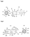
- a connecting surface 31 between an outer peripheral surface 11a and a shaft portion 16 in a leading end portion 15 of a shank section 11 shown in Figs. 6 and 8 is a ring-shaped flat surface nearly orthogonal to the center axis O.
- a taper portion 32 is formed between the shaft portion 16 and a key 17 over the entire periphery, and the key 17 having a substantially platelike shape is formed on a small-diameter leading end face 32a connected to the taper portion 32.
- a hole portion 26 is formed in a base end portion 25 of a head section 12 shown in Figs. 6 and 9, and a free end portion 33 thereof is a ring-shaped flat surface nearly orthogonal to the center axis O. Furthermore, a ring-shaped tapered portion 34 is formed between an inner peripheral surface 26a and a bottom face 26b of the hole portion 26 so as to be shrinkage-fitted on the taper portion 32. In this case, an interference is formed in the tapered portion 34 (or the taper portion 32, or both), and the corresponding inner diameter is set to be smaller than the outer diameter of the taper portion 32 by the interference.
- the inclination angle ⁇ of the tapered portion 34 of the hole portion 26 and the taper portion 32 of the shaft portion 16 with respect to the center axis O is set as shown in Fig. 7.
- a substantially platelike key groove 27 is formed on the bottom face 26b.
- two-surface restraint can also be established by shrinkage fitting between the inner peripheral surface 26a of the hole portion 26 and the outer peripheral surface 16a of the shaft portion 16, and between the tapered portion 34 and the taper portion 32.
- shrinkage fitting between the inner peripheral surface 26a of the hole portion 26 and the outer peripheral surface 16a of the shaft portion 16, and between the tapered portion 34 and the taper portion 32.
- the head section 12 is made of steel and the shank section 11 is made of cemented carbide in the above embodiment, the materials of the members are not limited to these materials, and various kinds of materials may be adopted.
- the members need not always be made of different materials, but may also be made of the same material.
- shank section 11 includes the shaft portion 16 and the taper portion 18 or 32
- head section 12 includes the hole portion 26 and the tapered portion 28 or 34 in the above description
- shank section 11 including the hole portion 26 and the tapered portion 28 or 34 and the head section 12 including the shaft portion 16 and the taper portion 18 or 32 may be shrinkage-fitted.
- boring bar 10 is described in the above embodiment, the present invention is also applicable to various types of cutting tools, for example, other turning tools such as a single-point tool, and various milling tools such as an endmill and a drill.
- a ball endmill 110 shown in Figs. 10 and 11 is formed by combining a head section 111 and a shank section 112 into one by shrinkage fitting at a fitting section 113.
- the head section 111 is made of, for example, cemented carbide, cermet, or ceramic.
- An outer peripheral surface 111c thereof is substantially cylindrical, and a leading end portion 111a is formed in a substantially hemispherical shape.
- Mounted in the leading end portion 111a is a throwaway tip or a cutting edge (not shown).
- a shaft portion 114 in the shape of, for example, a substantially truncated cone having a smaller diameter than that of the outer peripheral surface 111c is formed, and the outer periphery thereof serves as a ring-shaped contact face 115 (shaft portion contact face).
- the shaft portion 114 includes a peripheral surface 114a in the shape of a peripheral surface of a truncated cone, and a circular end face 114b that has the maximum outer diameter at the leading end, that is, the free end of the shaft portion 114.
- the outer shape of the shaft portion 114 is tapered so that the outer diameter gradually increases from a portion connected to the contact face 115 toward the end face 114b.
- the shaft portion 114 is formed coaxially with the center axis O1 of the head section 111.
- the shank section 112 is made of a material having a higher coefficient of thermal expansion (coefficient of linear expansion) than that of the head section 111, for example, steel, and is substantially cylindrical.
- the outer diameter of an outer peripheral surface 112c is set to be almost the same as the outer diameter of the outer peripheral surface 111c of the head section 111.
- a leading end portion 112a is provided with a hole portion 117 in the shape of, for example, a substantially truncated cone having a smaller diameter than that of the outer peripheral surface 112c.
- a ring-shaped contact face 118 (hole portion contact face) is formed on the outer peripheral side thereof.
- the hole portion 117 includes an inner peripheral surface 117a in the shape of a peripheral surface of a truncated cone, and a circular bottom face 117b.
- the inner peripheral surface 117a is formed so that the inner diameter gradually increases from an opening portion connected to the contact face 118 toward the bottom face 117b.
- the hole portion 117 is formed coaxially with the center axis O2 of the shank section 112.
- the shaft portion 114 of the head section 111 and the hole portion 117 of the shank section 112 are fitted together by shrinkage fitting, thereby constituting the fitting section 113.
- the center axis O of the ball endmill 110 coincides with the center axis O1 of the head section 111 and the center axis O2 of the shank section 112.
- An outer diameter d1 of the peripheral surface 114a of the shaft portion 114 gradually increases from the portion connected to the contact face 115 toward the end face 114b, and an inner diameter d2 of the inner peripheral surface 117a of the hole portion 117 gradually increases from the portion connected to the contact face 118 toward the bottom face 117b.
- the depth of the hole portion 117 of the shank section 112 in the direction of the center axis O2 is set to be slightly larger than the length of the shaft portion 114 of the head section 111 in the direction of the center axis O1, and a small space 120 is formed between the end face 114b of the shaft portion 114 and the bottom face 117b of the hole portion 117 in a fitted state shown in Figs. 10 and 11 in which the contact faces 115 and 118 of the head section 111 and the shank section 112 are in contact with each other.
- the outer diameter d1 of the shaft portion 114 in a cross section at an arbitrary position intersecting the center axis O (hereinafter referred to as an "axis-intersecting cross section") is set to be slightly larger than the inner diameter d2 of the hole portion 117.
- the size difference (d1 - d2) therebetween in an arbitrary axis-intersecting cross section serves as an interference in shrinkage-fitting the shaft portion 114 in the hole portion 117.
- the tapered peripheral surface 114a of the shaft portion 114 is inclined from the portion connected to the contact face 115 toward the end face 114b at a small angle ⁇ 1 with respect to the center axis O1. Furthermore, the contact face 115 is inclined at a small angle ⁇ 1 with respect to a radial line R1 orthogonal to the center axis O1. For this reason, the crossing angle formed between the contact face 115 and the outer peripheral surface 111c is obtuse.
- the tapered inner peripheral surface 117a of the hole portion 117 is inclined from the portion connected to the contact face 118 toward the bottom face 117b at a small angle ⁇ 2 with respect to the center axis O2. Furthermore, the contact face 118 is inclined at a small angle ⁇ 2 with respect to a radial line R2 orthogonal to the center axis O2. For this reason, the crossing angle formed between the contact face 118 and the outer peripheral surface 112c is acute.
- ⁇ 2 may be set so that the crossing angle is obtuse.
- ⁇ 1 is also set so that the crossing angle between the contact face 115 and the outer peripheral surface 111c is acute.
- a chamfered portion 121 is formed over the entire periphery in connection with the shaft portion 114.
- angles ⁇ 1 and ⁇ 2 have the following relations: (1/10000)° ⁇ ⁇ 1 ⁇ 2° and (1/10000)° ⁇ ⁇ 2 ⁇ 2° and ⁇ 1 ⁇ ⁇ 2
- angles ⁇ 1 and ⁇ 2 have the following relations: 0° ⁇ ⁇ 1 and 0° ⁇ ⁇ 2 and ⁇ 1 ⁇ ⁇ 2 (4)
- the free end of the shaft portion 114 (the adjacency of the end face 114b) can be pressed and pulled in by the inner peripheral surface 117a of the hole portion 117 during cooling, thereby further increasing the pull-in fitting strength.
- the ball endmill 110 of this embodiment has the above-described configuration. Next, a fitting method therefor will be described.
- the shank section 112 is heated to a temperature higher than ordinary temperature. While the inner diameter d2 of the chamfered portion 121 serving as the opening of the hole portion 117 in the shank section 112 is made greater than the outer diameter d1 of the end face 114b serving as the largest outer diameter of the shaft portion 114, the shaft portion 114 and the hole portion 117 are fitted to a position where the contact faces 115 and 118 contact with each other, thereby establishing shrinkage fitting.
- the hole portion 117 contracts and decreases its diameter. Therefore, the shaft portion 114 is firmly shrinkage-fitted in the hole portion 117 by the pressure of interferences corresponding to differences (d1 - d2) in diameter between the shaft portion 114 and the hole portion 117 in the axis-intersecting cross sections along the longitudinal direction of the center axis O.
- the shaft portion 114 and the hole portion 117 are subjected to shrinkage fitting, since the peripheral surface 114a of the shaft portion 114 and the inner peripheral surface 117a of the hole portion 117 have the inclination angles ⁇ 1 and ⁇ 2, the peripheral surface 114a adjacent to the end face 114b serving as the free end of the shaft portion 114 or the overall peripheral surface 114a is pressed by the inner peripheral surface 117a of the hole portion 117 that contracts with cooling according to the expression (2). Therefore, the shaft portion 114 is pulled into the hole portion 117 toward the bottom face 117b by the pressure of the interference corresponding to the size difference (d1 - d2) in the axis-intersecting cross section, which establishes firmer fastening and fitting.
- the head section 111 and the shank section 112 are subjected to two-surface restraint by shrinkage fitting of the shaft portion 114 and the hole portion 117.
- ⁇ 1 may be less than ⁇ 2.
- shrinkage fitting can be established by pressing the base portion of the shaft portion 114 connected to the contact face 115 by the hole portion 117, and precision is improved.
- ⁇ 1 may be equal to ⁇ 2.
- shrinkage fitting can be also performed by the pulling force.
- firm pull-in fitting can be established by the peripheral surface 114a of the shaft portion 114 and the inner peripheral surface 117a of the hole portion 117. Since the contact faces 115 and 118 contact with each other at the outer peripheral edges 115a and 118a, it is possible to prevent rattling due to pressure contact, to perform precise and firm pressure contact, and to establish firm and precise shrinkage fitting using two-surface restraint.
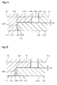
- Fig. 14 is a cross-sectional view showing the principal part of a fitting section in a first modification, similar to Fig. 11.
- a peripheral surface 114a of the shaft portion 114 and an inner peripheral surface 117a of the hole portion 117 have the same structures as those in the above-described third embodiment.
- a contact face 123 (shaft portion contact face) of the shaft portion 114 is a flat face nearly orthogonal to the center axis O1, and a projection 124 of rectangular cross section is formed at the overall outer peripheral edge of the contact face 123 so as to project in a direction nearly parallel to the center axis O1.
- a contact face 125 (hole portion contact face) of the hole portion 117 facing the contact face 123 is a flat surface nearly orthogonal to the center axis O2 to the outer peripheral edge intersecting an outer peripheral surface 112c.
- the projection 124 of the contact face 123 of the shaft portion is fixed in pressure contact with the contact face 125 of the hole portion 117 at the outer peripheral edges.
- Such a structure can also establish firm and precise fitting of the contact faces 123 and 125 without causing rattling.
- Fig. 15 is a cross-sectional view showing the principal part of a fitting section in a second modification, similar to Fig. 11.
- an outer peripheral surface 114a of the shaft portion 114 and an inner peripheral surface 117a of the hole portion 117 also have the same structures as those in the above-described first embodiment.
- a contact face 127 (shaft portion contact face) of the shaft portion 114 is a flat surface nearly orthogonal to the center axis O1.
- a contact face 128 (hole portion contact face) of the hole portion 117 facing the contact face 127 is a flat surface nearly orthogonal to the center axis O2.
- a projection 129 of rectangular cross section is formed at the overall outer peripheral edge thereof intersecting an outer peripheral surface 112c so as to project in a direction nearly parallel to the center axis O2.
- the contact faces 127 and 128 are pressed by the projection 129 at the outer peripheral edge in a manner similar to the first modification, and firm and precise fitting can be established without causing rattling.
- the above-described projection 124 or 129 is not limited to the above modifications, and may be formed on the contact faces 115 and 118 with the inclination angles ⁇ 1 and ⁇ 2 which have been described in the first embodiment.
- the head section 111 is made of cemented carbide or the like and is provided with the shaft portion 114 and the shank section 112 is made of a material having a higher coefficient of thermal expansion than that of the head section 111, for example, steel, and is provided with the hole portion 117 in the above embodiments, they may have reverse structures.
- a head section 111 is made of a material having a higher coefficient of thermal expansion than that of a shank section 112, for example, steel, and is provided with a hole portion 117.
- the shank section 112 is made of a material having a lower coefficient of thermal expansion than that of the head section 111, such as cemented carbide, cermet, or ceramic, and is provided with a shaft portion 114.
- a contact face 118 is formed on the outer peripheral side of the hole portion 117 in the head section 111, and a contact face 115 is formed on the outer peripheral side of the shaft portion 114 in the shank section 112.
- a fourth embodiment of the present invention will be described with reference to Fig. 17 as a longitudinal sectional view of a ball endmill.
- the same or similar members as or to those in the above embodiments are denoted by the same numerals, and description thereof is omitted.
- both a head section 111 and a shank section 112 are made of a material having a low coefficient of thermal expansion, such as cemented carbide, cermet, or ceramic.
- a material having a low coefficient of thermal expansion such as cemented carbide, cermet, or ceramic.
- the shank section 112 of the material having high hardness and high rigidity, such as cemented carbide, the vibration-isolating effect is improved during cutting or the like.
- the head section 111 has the same structure as that in the above-described third embodiment, and is provided with a tapered shaft portion 114 in a base end portion 111b.
- a second shaft portion 131 projects coaxially with the center axis O2, and a ring-shaped second contact face 132 (shaft portion contact face) is formed in the radial direction on the outer periphery thereof.
- the second shaft portion 131 is shaped nearly like a truncated cone having an outer diameter d1 that is almost the same as that of the shaft portion 114 in the head section 111.
- the second shaft portion 131 includes a tapered peripheral surface 131a and an end face 131b.
- the outer diameter d1 of the second shaft portion 131 gradually increases from the portion connected to the second contact face 132 toward the end face 131b, and the inclination angle ⁇ 1 is the same as that of the shaft portion 114.
- the second contact face 132 is placed at an angle ⁇ 1 with respect to the radial line direction orthogonal to the center axis O2, in a manner similar to the contact face 115 of the head section 111, and is inclined toward the opposite side so as to face the contact face 115.
- a substantially cylindrical connecting member 134 is provided to shrinkage-fit the shaft portion 114 of the head section 111 and the second shaft portion 131 of the shank section 112 that face each other.
- the connecting member 134 is made of a material having a higher coefficient of thermal expansion than those of the head section 111 and the shank section 112, for example, steel, and an inner peripheral surface 135 thereof is composed of a first inclined portion 135a and a second inclined portion 135b, as viewed in the direction of the center axis O3.
- the first inclined portion 135a and the second inclined portion 135b are tapered so that the inner diameter gradually decreases from the center intersection toward both ends.
- first and second inclined portions 135a and 135b have the gradually varying inner diameter d2 that is the same as that of the hole portion 117 in the above-described third embodiment.
- the differences (d1 - d2) between the outer diameters d1 and d1 of the shaft portion 114 and the second shaft portion 131 and the inner diameters d2 and d2 of the first and second inclined portions 135a and 135b serve as interferences.
- first and second inclined portions 135a and 135b are formed to be inclined at angles ⁇ 2 and ⁇ 2 with respect to the center axis O3.
- the relationship between the inclination angles ⁇ 1 and ⁇ 1 of the shaft portion 114 of the head section 111 and the second shaft portion 131 of the shank section 112 with respect to the center axes O1 and O2 satisfies the above-described expressions (1) and (2).
- the length L of the first inclined portion 135a and the second inclined portion 135b of the connecting member 134 along the center axis O3 are set to be larger than the length L1 of the shaft portion 114 and the length L2 of the second shaft portion 131 in the same direction.
- 2L is set to be longer than the sum of L1 and L2.
- a space 120 is formed between the inner peripheral surface 135 of the connecting member 134 and the shaft portions 114 and 131, and the length thereof in the direction of the center axis O3 is equal to 2L - (L1 + L2) .
- the center axes O1, O2, and O3 are coaxial, and coincide with the center axis O of the ball endmill 130.
- Both end faces 136a and 136b of the connecting member 134 form inclined surfaces so that the length therebetween gradually decreases from the outer peripheral side toward the inner peripheral surface 135.
- the end faces 136a and 136b are inclined at the inclination angles ⁇ 2 and ⁇ 2 with respect to the radial line direction orthogonal to the center axis O3. For this reason, the inclination angles ⁇ 2 and ⁇ 2 satisfy the relationships, which are given by the above expressions (3) and (4), with the inclination angles ⁇ 1 and ⁇ 1 of the contact face 115 of the head section 111 and the second contact face 132 of the shank section 112.
- this embodiment has the above-described configuration, while the connecting member 134 is heated to increase its diameter, the shaft portion 114 of the head section 111 and the second shaft portion 131 of the shank section 112 are inserted into the connecting member 134 from both ends, and are shrinkage-fitted together.
- the shaft portion 114 is pulled in by the first inclined portion 135a of the connecting member 134
- the second shaft portion 131 is pulled in by the second inclined portion 135b
- the shaft portions are fixed by the interference (d1 - d2) in an arbitrary axis-intersecting cross section.
- the contact faces 115 and 132 of the head section 111 and the shank section 112 are in contact with the both end faces 136a and 136b of the connecting member 134, and reliably contact at the outer peripheral edges.
- both the head section 111 and the shank section 112 have high stiffness and provide a high degree of effectiveness of vibration isolation.
- two-surface restraint can also be established by shrinkage fitting of the shaft portion 114, the second shaft portion 131, and the connecting member 134, thereby reliably improving tool stiffness.
- the head section 111, the shank section 112, and the connecting member 134 are made of steel, cemented carbide, or the like in the above embodiment, the materials of the members are not limited to these materials, and other various kinds of materials may be adopted.
- the members need not always be made of different materials, and may be made of the same material.
- the present invention is also applicable to various types of cutting tools, for example, other turning tools such as a single-point tool, and various milling tools such as an endmill and a drill.
- the tool and the tool holding portion may be fitted not only by shrinkage fitting, but also by expansion fitting.
Landscapes
- Engineering & Computer Science (AREA)
- Mechanical Engineering (AREA)
- Cutting Tools, Boring Holders, And Turrets (AREA)
- Milling Processes (AREA)
Applications Claiming Priority (2)
| Application Number | Priority Date | Filing Date | Title |
|---|---|---|---|
| JP10350405A JP2000176724A (ja) | 1998-12-09 | 1998-12-09 | 嵌合式切削工具 |
| JP35040598 | 1998-12-09 |
Publications (2)
| Publication Number | Publication Date |
|---|---|
| EP1008408A2 true EP1008408A2 (fr) | 2000-06-14 |
| EP1008408A3 EP1008408A3 (fr) | 2003-01-08 |
Family
ID=18410281
Family Applications (1)
| Application Number | Title | Priority Date | Filing Date |
|---|---|---|---|
| EP99123277A Withdrawn EP1008408A3 (fr) | 1998-12-09 | 1999-11-30 | Outil de coupe type ajustement serré |
Country Status (4)
| Country | Link |
|---|---|
| US (1) | US6312201B1 (fr) |
| EP (1) | EP1008408A3 (fr) |
| JP (1) | JP2000176724A (fr) |
| KR (1) | KR20000047745A (fr) |
Cited By (2)
| Publication number | Priority date | Publication date | Assignee | Title |
|---|---|---|---|---|
| US8460763B2 (en) | 2007-03-01 | 2013-06-11 | Plasmatrix Materials Ab | Method for enhancing dynamic stiffness |
| US20230040385A1 (en) * | 2021-08-04 | 2023-02-09 | Celeritive Technologies, Inc. | Methods for preventing notch formation in, and/or extending the useful life of, cutting tools for turning, and associated systems |
Families Citing this family (29)
| Publication number | Priority date | Publication date | Assignee | Title |
|---|---|---|---|---|
| JP2001087925A (ja) * | 1999-09-14 | 2001-04-03 | Osg Corp | 回転切削工具および連接部材 |
| DE19958832A1 (de) * | 1999-11-30 | 2001-05-31 | Otto Bilz, Werkzeugfabrik Gmbh & Co | Spannfutter zum Spannen von Werkzeugen durch Schrumpfsitz |
| US8123814B2 (en) | 2001-02-23 | 2012-02-28 | Biomet Manufacturing Corp. | Method and appartus for acetabular reconstruction |
| US7597715B2 (en) | 2005-04-21 | 2009-10-06 | Biomet Manufacturing Corp. | Method and apparatus for use of porous implants |
| JP2003117703A (ja) * | 2001-10-11 | 2003-04-23 | Ngk Spark Plug Co Ltd | シャンク及び切削工具 |
| DE10206168A1 (de) * | 2002-02-14 | 2003-08-21 | Guehring Joerg | Kupplung für mudular aufgebaute Werkzeughalterarme |
| JP4288905B2 (ja) * | 2002-07-18 | 2009-07-01 | 三菱マテリアル株式会社 | 刃部交換式切削工具及びリング部材 |
| USD508507S1 (en) * | 2002-08-28 | 2005-08-16 | Hartmetall-Werkzeugfabrik Paul Horn Gmbh | Boring and drilling system |
| US8573901B2 (en) * | 2003-09-02 | 2013-11-05 | Kennametal Inc. | Assembly for rotating a cutting insert during a turning operation and inserts used therein |
| DE10341976A1 (de) * | 2003-09-11 | 2005-04-28 | Mapal Fab Praezision | Werkzeug und Verfahren zur spanenden Feinbearbeitung von Werkstücken |
| EP1535682A1 (fr) * | 2003-11-26 | 2005-06-01 | Sumitomo Electric Hardmetal Corp. | Suppression des vibrations |
| US7077608B2 (en) * | 2004-04-22 | 2006-07-18 | Parlec, Inc. | System for mounting a machine tool in a holder |
| US7240593B2 (en) * | 2005-04-19 | 2007-07-10 | Roger Little | Miniature cutting insert holder |
| US8066778B2 (en) | 2005-04-21 | 2011-11-29 | Biomet Manufacturing Corp. | Porous metal cup with cobalt bearing surface |
| US8266780B2 (en) * | 2005-04-21 | 2012-09-18 | Biomet Manufacturing Corp. | Method and apparatus for use of porous implants |
| AU2005202371B2 (en) * | 2005-05-31 | 2010-09-23 | Sandvik Intellectual Property Ab | Method for manufacturing a cutting pick |
| DE202005014350U1 (de) * | 2005-09-09 | 2005-11-10 | Haimer Gmbh | Werkzeughalter zur Schrumpfbefestigung von Werkzeugen |
| SE532394C2 (sv) * | 2007-06-04 | 2010-01-12 | Sandvik Intellectual Property | Verktyg för spånavskiljande bearbetning samt grundkropp härför |
| US7959387B2 (en) * | 2007-10-03 | 2011-06-14 | Kennametal Inc. | Shrink fit sleeve for tool holder |
| IL196764A (en) * | 2009-01-28 | 2013-02-28 | Iscar Ltd | Clamping mechanism |
| US20110017562A1 (en) * | 2009-07-21 | 2011-01-27 | Hapco Aluminum Pole Products | Vibration damping system for utility poles |
| US20110262232A1 (en) * | 2010-04-23 | 2011-10-27 | Chin-Chiu Chen | Lathe blade assembly |
| US8827610B2 (en) * | 2011-08-05 | 2014-09-09 | Kennametal Inc. | Hydraulic coupling system for coupling a shell mill to an adapter |
| US8899038B2 (en) * | 2011-09-01 | 2014-12-02 | The Johns Hopkins University | Release actuator employing components with different coefficients of thermal expansion |
| US9702385B2 (en) * | 2014-05-15 | 2017-07-11 | Iscar, Ltd. | Machine tool assembly configured for swift disassembly |
| EP3042729B1 (fr) * | 2015-01-12 | 2021-03-10 | Sandvik Intellectual Property AB | Fraise à céramique |
| JP6779337B1 (ja) * | 2019-04-26 | 2020-11-04 | 株式会社牧野フライス製作所 | T形工具およびt形工具の製作方法 |
| US11446746B2 (en) * | 2019-12-10 | 2022-09-20 | Iscar, Ltd. | Replaceable cutting head having back-tapered conical external thread and rotary cutting tool |
| JP7516234B2 (ja) * | 2020-12-10 | 2024-07-16 | オークマ株式会社 | ワークの旋削加工方法及び工作機械 |
Family Cites Families (34)
| Publication number | Priority date | Publication date | Assignee | Title |
|---|---|---|---|---|
| DE246715C (fr) * | ||||
| FR1243161A (fr) * | 1958-12-23 | 1960-10-07 | Schiess Ag | Coulisseau et porte-outil pour machines-outils, notamment tours verticaux |
| US3027953A (en) * | 1961-04-10 | 1962-04-03 | Bernard F Coski | Percussion tool with replaceable point |
| US3100545A (en) * | 1961-04-11 | 1963-08-13 | Ingersoll Rand Co | Drill bit |
| US3655244A (en) * | 1970-07-30 | 1972-04-11 | Int Tool Sales | Impact driven tool with replaceable cutting point |
| US4047583A (en) * | 1976-06-01 | 1977-09-13 | Dresser Industries, Inc. | Earth boring cutting element retention system |
| US3994615A (en) | 1975-06-12 | 1976-11-30 | Narang Rajendra K | Multiple part cutting tool |
| SU1007843A1 (ru) * | 1980-07-04 | 1983-03-30 | Краматорский Научно-Исследовательский И Проектно-Технологический Институт Машиностроения | Расточна оправка |
| CH656334A5 (de) * | 1982-06-28 | 1986-06-30 | Kaiser Heinz Ag | Ausdrehwerkzeug. |
| US4452325A (en) | 1982-09-27 | 1984-06-05 | Conoco Inc. | Composite structure for cutting tools |
| DE3500905A1 (de) * | 1985-01-12 | 1986-07-17 | Wolfgang 7401 Dusslingen Zürn | Werkzeughalter |
| DE8513540U1 (de) * | 1985-05-08 | 1985-06-27 | Paul Forkardt GmbH & Co KG, 4000 Düsseldorf | Vorrichtung zum Festspannen von Werkzeugen an einem Werkzeugträger einer Werkzeugmaschine |
| US4945793A (en) * | 1985-09-14 | 1990-08-07 | Fried. Krupp Gesellschaft Mit Beschrankter Haftung | Tool coupling |
| DE3642132C1 (de) * | 1986-12-10 | 1988-03-24 | Krupp Gmbh | Werkzeugkupplung zur Verbindung eines Werkzeugschaftes und eines Werkzeughalters |
| SU1346350A2 (ru) * | 1985-10-08 | 1987-10-23 | Экспериментальный научно-исследовательский институт металлорежущих станков | Устройство дл автоматической подналадки резца |
| JPS62124807A (ja) * | 1985-11-25 | 1987-06-06 | Hitachi Constr Mach Co Ltd | ボ−リング加工用刃具構造 |
| DE3607938A1 (de) | 1986-03-11 | 1987-09-17 | Gewerk Eisenhuette Westfalia | Hobelmeissel, insbesondere fuer kohlenhobel |
| US4747735A (en) * | 1987-01-27 | 1988-05-31 | Kennametal Inc. | Toolholder and method of releasably mounting |
| SE457623B (sv) * | 1987-04-21 | 1989-01-16 | Sandvik Ab | Verktygskoppling |
| SU1450922A1 (ru) * | 1987-06-10 | 1989-01-15 | Научно-Производственное Объединение "Спецтехоснастка" | Регулируема резцова вставка |
| JPH0247139U (fr) | 1988-09-22 | 1990-03-30 | ||
| EP0437322B1 (fr) | 1990-01-08 | 1994-05-18 | Kabushiki Kaisha Mori Seiki Seisakusho | Broche pour machine outil |
| DE69207464T2 (de) * | 1991-03-13 | 1996-07-18 | Mitsubishi Materials Corp | Schneidwerkzeug |
| US5193954A (en) * | 1991-10-30 | 1993-03-16 | Gte Valenite Corporation | Universal tool connection |
| DE4139573C2 (de) * | 1991-11-30 | 1995-04-20 | Krupp Widia Gmbh | Werkzeughalter-Justiervorrichtung |
| US5173017A (en) * | 1991-12-20 | 1992-12-22 | Kennametal Inc. | Apparatus to adapt a toolholder for mounting to a base member |
| US5280671A (en) | 1992-05-12 | 1994-01-25 | Fx Marquart Gmbh | Process and device for clamping tools in a clamping chuck |
| ZA93584B (en) * | 1992-05-27 | 1993-09-01 | De Beers Ind Diamond | Abrasive tools. |
| JPH0631506A (ja) * | 1992-07-21 | 1994-02-08 | Mitsubishi Materials Corp | ボーリングバー |
| US5617602A (en) * | 1995-06-27 | 1997-04-08 | Okada; Eiji | Motor-driven toothbrush |
| JPH1053470A (ja) | 1996-08-05 | 1998-02-24 | Ngk Insulators Ltd | セラミックス接合体およびその製造方法 |
| IL120948A0 (en) * | 1997-05-29 | 1997-09-30 | Iscar Ltd | Cutting tool assembly |
| EP0911101A1 (fr) * | 1997-10-22 | 1999-04-28 | Fraisa Sa | Outil d'usinage |
| US6234729B1 (en) * | 1999-04-28 | 2001-05-22 | Harold D. Cook | Shrink fit shoulder interface |
-
1998
- 1998-12-09 JP JP10350405A patent/JP2000176724A/ja active Pending
-
1999
- 1999-11-15 US US09/440,279 patent/US6312201B1/en not_active Expired - Lifetime
- 1999-11-27 KR KR1019990053228A patent/KR20000047745A/ko not_active Withdrawn
- 1999-11-30 EP EP99123277A patent/EP1008408A3/fr not_active Withdrawn
Cited By (2)
| Publication number | Priority date | Publication date | Assignee | Title |
|---|---|---|---|---|
| US8460763B2 (en) | 2007-03-01 | 2013-06-11 | Plasmatrix Materials Ab | Method for enhancing dynamic stiffness |
| US20230040385A1 (en) * | 2021-08-04 | 2023-02-09 | Celeritive Technologies, Inc. | Methods for preventing notch formation in, and/or extending the useful life of, cutting tools for turning, and associated systems |
Also Published As
| Publication number | Publication date |
|---|---|
| KR20000047745A (ko) | 2000-07-25 |
| US6312201B1 (en) | 2001-11-06 |
| JP2000176724A (ja) | 2000-06-27 |
| EP1008408A3 (fr) | 2003-01-08 |
| US20010041106A1 (en) | 2001-11-15 |
Similar Documents
| Publication | Publication Date | Title |
|---|---|---|
| US6312201B1 (en) | Interference fit type cutting tool | |
| KR101291024B1 (ko) | 인서트식 절삭 공구, 인서트 및 인서트의 공구 본체로의고정 방법 | |
| US7713004B2 (en) | Tool for chip removing machining as well as a basic body therefore | |
| US6514019B1 (en) | Boring tool comprising a replaceable cutting insert which is secured against detaching | |
| EP1328366B1 (fr) | Outil pivotant dont l'extremite libre d'enlevement de copeaux est pourvue d'une partie active remplacable | |
| US7101127B2 (en) | Interchangeable blade cutting tool and blade section installed thereon | |
| US6595729B2 (en) | Drill with countersinker for chip removing machining | |
| US8656573B2 (en) | Shrink-fit tool with mechanical retention member, and method of mounting a tool to a toolholder | |
| EP1273373A1 (fr) | Outil rotatif avec tête de coupe remplaçable | |
| US11801562B2 (en) | Tool for machining a workpiece | |
| US10124421B2 (en) | End milling cutter for heat-resistant superalloys | |
| US9999929B2 (en) | Cutting head and cutting tool having a replaceable cutting head | |
| US7320566B2 (en) | Cutting tool including detachable cutter head | |
| US20080101878A1 (en) | Tool for cutting machining | |
| HK1034692A (en) | Interference fit type cutting tool | |
| US20010031177A1 (en) | Interference fit type cutting tool | |
| KR102826261B1 (ko) | 보링 공구 및 절삭 인서트 | |
| JP3539210B2 (ja) | ヘッド交換式切削工具及びその製造方法 | |
| KR100473417B1 (ko) | 밀링절삭공구 | |
| JPH07285002A (ja) | 深部加工用の防振工具 | |
| JPH0426164Y2 (fr) | ||
| JP2003285217A (ja) | 嵌合式切削工具 | |
| JPH1043926A (ja) | 回転式切削工具 | |
| JPH0516010U (ja) | スローアウエイ式切削工具 | |
| KR20200122716A (ko) | 절삭공구의 축중심과 회전중심의 정렬 및 미세조정이 가능한 보링용 절삭공구 홀더 |
Legal Events
| Date | Code | Title | Description |
|---|---|---|---|
| PUAI | Public reference made under article 153(3) epc to a published international application that has entered the european phase |
Free format text: ORIGINAL CODE: 0009012 |
|
| AK | Designated contracting states |
Kind code of ref document: A2 Designated state(s): AT BE CH CY DE DK ES FI FR GB GR IE IT LI LU MC NL PT SE |
|
| AX | Request for extension of the european patent |
Free format text: AL;LT;LV;MK;RO;SI |
|
| PUAL | Search report despatched |
Free format text: ORIGINAL CODE: 0009013 |
|
| AK | Designated contracting states |
Kind code of ref document: A3 Designated state(s): AT BE CH CY DE DK ES FI FR GB GR IE IT LI LU MC NL PT SE |
|
| AX | Request for extension of the european patent |
Free format text: AL;LT;LV;MK;RO;SI |
|
| RIC1 | Information provided on ipc code assigned before grant |
Free format text: 7B 23B 31/02 A, 7B 23B 29/02 B |
|
| 17P | Request for examination filed |
Effective date: 20021218 |
|
| AKX | Designation fees paid |
Designated state(s): DE ES FR GB IT SE |
|
| 17Q | First examination report despatched |
Effective date: 20040318 |
|
| STAA | Information on the status of an ep patent application or granted ep patent |
Free format text: STATUS: THE APPLICATION IS DEEMED TO BE WITHDRAWN |
|
| 18D | Application deemed to be withdrawn |
Effective date: 20040729 |
|
| REG | Reference to a national code |
Ref country code: HK Ref legal event code: WD Ref document number: 1034692 Country of ref document: HK |