EP1008410A1 - Kreissägemaschine - Google Patents
Kreissägemaschine Download PDFInfo
- Publication number
- EP1008410A1 EP1008410A1 EP99922505A EP99922505A EP1008410A1 EP 1008410 A1 EP1008410 A1 EP 1008410A1 EP 99922505 A EP99922505 A EP 99922505A EP 99922505 A EP99922505 A EP 99922505A EP 1008410 A1 EP1008410 A1 EP 1008410A1
- Authority
- EP
- European Patent Office
- Prior art keywords
- main shaft
- circular saw
- cutting
- inertia
- kgf
- Prior art date
- Legal status (The legal status is an assumption and is not a legal conclusion. Google has not performed a legal analysis and makes no representation as to the accuracy of the status listed.)
- Withdrawn
Links
Images




Classifications
-
- B—PERFORMING OPERATIONS; TRANSPORTING
- B23—MACHINE TOOLS; METAL-WORKING NOT OTHERWISE PROVIDED FOR
- B23D—PLANING; SLOTTING; SHEARING; BROACHING; SAWING; FILING; SCRAPING; LIKE OPERATIONS FOR WORKING METAL BY REMOVING MATERIAL, NOT OTHERWISE PROVIDED FOR
- B23D47/00—Sawing machines or sawing devices working with circular saw blades, characterised only by constructional features of particular parts
- B23D47/005—Vibration-damping
-
- B—PERFORMING OPERATIONS; TRANSPORTING
- B23—MACHINE TOOLS; METAL-WORKING NOT OTHERWISE PROVIDED FOR
- B23D—PLANING; SLOTTING; SHEARING; BROACHING; SAWING; FILING; SCRAPING; LIKE OPERATIONS FOR WORKING METAL BY REMOVING MATERIAL, NOT OTHERWISE PROVIDED FOR
- B23D47/00—Sawing machines or sawing devices working with circular saw blades, characterised only by constructional features of particular parts
- B23D47/12—Sawing machines or sawing devices working with circular saw blades, characterised only by constructional features of particular parts of drives for circular saw blades
-
- Y—GENERAL TAGGING OF NEW TECHNOLOGICAL DEVELOPMENTS; GENERAL TAGGING OF CROSS-SECTIONAL TECHNOLOGIES SPANNING OVER SEVERAL SECTIONS OF THE IPC; TECHNICAL SUBJECTS COVERED BY FORMER USPC CROSS-REFERENCE ART COLLECTIONS [XRACs] AND DIGESTS
- Y10—TECHNICAL SUBJECTS COVERED BY FORMER USPC
- Y10T—TECHNICAL SUBJECTS COVERED BY FORMER US CLASSIFICATION
- Y10T83/00—Cutting
- Y10T83/081—With randomly actuated stopping means
- Y10T83/088—Responsive to tool detector or work-feed-means detector
- Y10T83/089—Responsive to tool characteristic
-
- Y—GENERAL TAGGING OF NEW TECHNOLOGICAL DEVELOPMENTS; GENERAL TAGGING OF CROSS-SECTIONAL TECHNOLOGIES SPANNING OVER SEVERAL SECTIONS OF THE IPC; TECHNICAL SUBJECTS COVERED BY FORMER USPC CROSS-REFERENCE ART COLLECTIONS [XRACs] AND DIGESTS
- Y10—TECHNICAL SUBJECTS COVERED BY FORMER USPC
- Y10T—TECHNICAL SUBJECTS COVERED BY FORMER US CLASSIFICATION
- Y10T83/00—Cutting
- Y10T83/141—With means to monitor and control operation [e.g., self-regulating means]
- Y10T83/148—Including means to correct the sensed operation
-
- Y—GENERAL TAGGING OF NEW TECHNOLOGICAL DEVELOPMENTS; GENERAL TAGGING OF CROSS-SECTIONAL TECHNOLOGIES SPANNING OVER SEVERAL SECTIONS OF THE IPC; TECHNICAL SUBJECTS COVERED BY FORMER USPC CROSS-REFERENCE ART COLLECTIONS [XRACs] AND DIGESTS
- Y10—TECHNICAL SUBJECTS COVERED BY FORMER USPC
- Y10T—TECHNICAL SUBJECTS COVERED BY FORMER US CLASSIFICATION
- Y10T83/00—Cutting
- Y10T83/141—With means to monitor and control operation [e.g., self-regulating means]
- Y10T83/159—Including means to compensate tool speed for work-feed variations
Definitions
- the present invention relates to a circular saw cutting machine and particularly relates to a circuit saw cutting machine for preventing chatter vibration generated by cutting a metallic work material.
- a circular saw cutting machine of this type reduces the rotation of an electric motor through a pulley and a gear mechanism provided in a gear box and transmits the reduced rotation to a main shaft, has a circular saw attached to one end of the main shaft which end protrudes from the gear box, rotates the main shaft at a low speed with a high torque and thereby cuts a metallic work material. Since the circular saw cutting machine uses gears in a rotation transmission section as stated above, the backlash of gears occurs.
- a circular saw cutting device designed to prevent such rotational variation of the gears, as shown in, for example, Japanese Utility Model Examined Application Publication No. 62-28334, pressing pieces are provided on both sides of the circular saw, one of the pieces actuating a hydraulic cylinder to thereby apply a frictional force before the start of cutting operation.
- a control shaft is directly coupled to a main shaft, to which a circular saw is attached, through a gear and a braking device is provided at the control shaft.
- this circular saw cutting device from the start to the end of cutting operation by means of the circular saw, the backlash of the gears of a drive system is suppressed while a braking force is electrically controlled by a solenoid proportional valve, thereby eliminating the chatter vibration of the circular saw during the cutting operation.
- the above-stated circular saw cutting device is, however, designed to apply a braking force to the driving system at the start and end of the cutting operation to thereby forcedly eliminate the backlash of the gears and to perform the cutting operation while reducing cutting power.
- the mechanical structure is complicated and an electric control structure is required, with the result that the machine disadvantageously becomes expensive and the maintenance of the machine requires more labor.
- the present invention has been made to solve the above disadvantages. It is, therefore, an object of the present invention to provide a circular saw cutting machine capable of eliminating the chatter vibration of a circular saw during cutting operation to thereby enhance cutting accuracy, prolonging the service life of the circular saw and suppressing the occurrence of noise at low cost.
- the characteristic in constitution of the first invention lies in a circular saw cutting machine for transmitting the rotation of an electric motor to a main shaft and for cutting a work material by using a circular saw attached to one end of the main shaft, characterized in that if an outside diameter of the circular saw is D (mm), the number of revolution is N (rpm) and a cutting force per tooth as a component of force in tangential direction is F (kgf), a moment of inertia I (kgf ⁇ m ⁇ sec 2 ) of the main shaft is set at I ⁇ F ⁇ (D/2)/[1000 ⁇ 250 ⁇ (N/60) 2 ].
- the characteristic in constitution of the second invention lies in a circular saw cutting machine for transmitting the rotation of an electric motor to a main shaft and for cutting a work material by using a circular saw attached to one end of the main shaft, characterized in that a flywheel is attached either directly to the shaft or to a shaft extended from the main shaft; and if an outside diameter of the circular saw is D (mm), the number of revolution is N (rpm) and a cutting force per tooth as a component of force in tangential direction is F (kgf), a moment of inertia I (kgf ⁇ m ⁇ sec 2 ) of the overall main shaft including said flywheel is set at I ⁇ F ⁇ (D/2)/[1000 ⁇ 250 ⁇ (N/60) 2 ].
- the characteristic in constitution of the third invention lies in a circular saw cutting machine for transmitting the rotation of an electric motor to a main shaft and for cutting a work material by using a circular saw attached to one end of the main shaft, characterized in that if an outside diameter of the circular saw is D (mm), the number of revolution is N (rpm) and a cutting force per tooth as a component of force in tangential direction is F (kgf) , a sum J of moments of inertia (kgf ⁇ m ⁇ sec 2 ) of main shaft conversion of respective shafts including the main shaft, the respective shafts cooperated with one another in a state in which a backlash is eliminated from the main shaft is set at J ⁇ F ⁇ (D/2)/[1000 ⁇ 250 ⁇ (N/60) 2 ].
- power for rotating the main shaft is reduced by power transmission means (a reduction mechanism), such as a V-shaped belt, and transmitted from the pulley of the output shaft of the electric motor to the pulley of the main shaft to which the circular saw is attached.
- a reduction mechanism such as a V-shaped belt
- the moment of inertia I (kgf ⁇ m ⁇ sec 2 ) of the main shaft can be made higher than F ⁇ (D/2)/[1000 ⁇ 250 ⁇ (N/60) 2 ] .
- the flywheel can be attached either directly to the main shaft or to the extended main shaft.
- the moment of inertia of the main shaft but also the sum J of the moments of inertia of main shaft conversion of the respective shafts including the main shaft cooperated with one another through the reduction mechanism in a state in which no backlash occurs between the main shaft and gears in a drive system may be set to be higher than F ⁇ (D/2)/[1000 ⁇ 250 ⁇ (N/60) 2 ] .
- the smaller sum J of either the sum of the moments of inertia of the main shaft in the drive system or the sum of the moments of inertia of main shaft conversion of the respective shafts including the main shaft cooperated with one another through the acceleration/reduction mechanisms in a state in which no backlash occurs between the main shaft and the gears in the driven system may be set higher than F ⁇ (D/2)/[1000 ⁇ 250 ⁇ (N/60) 2 ].
- the characteristic in constitution of the forth invention lies in a circular saw cutting machine for transmitting the rotation of an electric motor to a main shaft and for cutting a work material by using a circular saw attached to one end of the main shaft, characterized in that a confining engagement gear string is constituted by arranging three or more odd-numbered intermediate gears forming a loop with a main shaft gear fixed to the main shaft, engaged with one another and simultaneously rotated, the rotation of the electric motor is transmitted to one of the intermediate gears, at least one of the intermediate gears is movable and a load is applied to at least one of the movable intermediate gears, thereby eliminating a backlash of the confining engagement gear string; and if an outside diameter of the circular saw is D (mm), the number of revolution is N (rpm) and a cutting force per tooth as a component of force in tangential direction is F (kgf), a sum J of moments of inertia (kgf ⁇ m ⁇ sec 2 ) of main shaft conversion of respective shafts including the main shaft, the
- the forth invention constituted as stated above, by attaching a flywheel having a necessary, sufficient moment of inertia to the shaft of at least one of the intermediate gears constituting a confining engagement gear string and applying a load to a movable intermediate gear, the backlash of the gears constituting the confining engagement gear string is eliminated and the sum J (kgf ⁇ m ⁇ sec 2 ) of the moments of inertia of main shaft conversion of the respective rotary shafts including the main shafts is set to be not less than F ⁇ (D/2)/[1000 ⁇ 250 ⁇ (N/60) 2 ].
- a pressure force can be easily regulated by a pressure regulation valve or the like provided in a hydraulic cylinder circuit. It is also possible to suppress wasteful power consumption and the wearing of gears by applying the pressure force only during cutting operation by using a switching valve and by stopping the application of the pressure force during slipping. Even if the wearing of gears progresses by the use of the machine for a long period of time, it is possible to maintain backlash free. Even if a gears is eccentric or there is an error in the shape of a gear, the eccentricity or error is absorbed by the extension of the hydraulic cylinder. Thus, there is no fear that an excessive load acts on the gear surface or bearing. Besides, since it is not necessary to use highly accurate gears, the cutting machine can be manufactured at low cost.
- backlash herein means not only backlash between gears but also rotational play in the respective rotary shafts within the transmission mechanism in which a rotational variation which is referred to as disadvantage in the present invention is generated.
- K F ⁇ (D/2)/[1000 ⁇ I ⁇ (N/60) 2 ] where K is a constant.
- the moment of inertia I can satisfy the Mathematical Expression 4. In that case, the rotational variation of gears caused by cutting force is not generated.
- various types of cutting tests were conducted. As a result, it was clear that if K is not less than 250 and the moment of inertia satisfies the relationship of the Mathematical Expression 4, then the rotational variation of gears caused by cutting force was eliminated.
- K 250 is used as a threshold value. Consequently, as stated above, the vibration damping of the main body of the cutting machine becomes greater than the rotational variation.
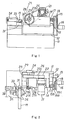
- FIG. 1 is a front view schematically showing a circular saw cutting machine A as the first embodiment according to the present invention.
- FIG. 2 is a plan view showing the circular saw cutting machine A.
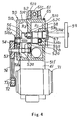
- FIG. 3 is a front view schematically showing a circular saw cutting machine B as the first embodiment.
- FIG. 4 is a cross-sectional view taken along line I-I of FIG. 3.
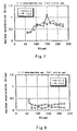
- FIG. 5 is a graph showing the relationship between the number of revolution of a main shaft and the maximum acceleration of the main body of the machine in the feed direction while cutting a work material if no flywheel is attached to the circular saw cutting machine A.
- FIG. 6 is a graph showing the relationship between the number of revolution of the main shaft and the maximum acceleration of the main body of the machine in the feed direction while cutting the work material if a flywheel is attached to the circular saw cutting machine A (condition 1).
- FIG. 7 is a graph showing the relationship between the number of revolution of the main shaft and the maximum acceleration of the main body of the machine in the feed direction while cutting the work material if no flywheel is attached to the circular saw cutting machine B.
- FIG. 8 is a graph showing the relationship between the number of revolution of the main shaft and the maximum acceleration of the main body of the machine in the feed direction while cutting the work material if a flywheel is attached to the circular saw cutting machine B (condition 6).
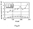
- FIG. 9 is a graph showing the relationship between the number of revolution of the main shaft and the maximum acceleration while cutting the work material with the circular saw cutting machine B having large cutting variation.
- FIG. 10 is an explanatory view for a constitution in which a flywheel is attached to the driven shaft of the circular saw cutting machine A.
- FIG. 11A and 11B are explanatory views for another constitutions in which a flywheel is attached to the driven shaft of the circular saw cutting machine A.
- FIG. 12 is a partially broken front view showing a swing-type circular saw cutting machine as the second embodiment.
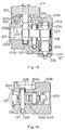
- FIG. 13 is a cross-sectional view taken along line X-X of FIG. 12.
- FIG. 14 is a cross-sectional view taken along line Y-Y of FIG. 12.
- FIG. 13 is a cross-sectional view taken along line X-X of FIG. 12.
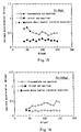
- FIG. 15 is a graph showing the relationship between the number of revolution N of a circular saw and the maximum acceleration (G-rms) of the vibration of a machine main body in a case where the load of a hydraulic cylinder is not applied to the intermediate gear of the circular saw cutting machine (pulley P3).
- FIG. 16 is a graph showing the relationship between the number of revolution N of the circular saw and the maximum acceleration (G-rms) of the vibration of the machine main body in a case where the load of a hydraulic cylinder is applied to the intermediate gear of the circular saw cutting machine (pulley P3).
- a constant K is determined by two types of circular saw cutting machines, i.e., a slide type and a swing type as the first embodiment, with reference to the drawings.
- FIGS. 1 and 2 show a slide-type circular saw cutting machine A as a front view and a plan view, respectively.
- the circular saw cutting machine A is provided with an oblong solid machine base 11.
- an oblong solid bed 12 is disposed to occupy about two-thirds in crosswise direction (note, the crosswise direction will hereinafter mean a direction seen from the front of the machine base 11).
- a pair of rails 13 extending in the crosswise direction are provided on the upper surface of the bed 12.
- An oblong solid movable base 14 is disposed to be slidable crosswise on the bed 12 by fitting a groove (not shown) provided in the bottom of base 14 into the rails 13.
- a drive support section 15 is fixed to the region from the generally intermediate position to the front side of the right side surface of the bed 12 in longitudinal direction and protrudes from the upper end of the bed 12 to be opposed to the movable base 14.
- the drive support section 15 includes a bottom plate 15a and a pair of parallel side plates 15b and 15c provided on crosswise ends of the bottom plate 15a, and is fixed to the bed 12 by the left side plate 15b.
- a servo motor 16 is fixed to the right of the right side plate 15c with a rotation shaft thereof directed in left direction.
- a ball screw 17 penetrates and is horizontally fixed to the left side plate 15b.
- the servo motor 16 and the ball screw 17 are coupled to each other with their respective pulleys (not shown) inserted into a V-shaped belt 18. By doing so, the rotation of the servo motor 16 is converted to a linear motion at the ball screw 17 and the movable base 14 is moved crosswise by the rectilinear propagation force of the ball screw 17.
- An electric motor 21 with a reduction gear is fixedly disposed at the right position on the upper surface of the movable base 14 with the rotation shaft thereof directed in backward direction.
- a drive pulley 22 is attached to the rotation shaft.
- a main shaft 23 is provided to penetrate the vertically intermediate position on the left end of the movable base 14 in longitudinal direction.
- the rear end of the main shaft 23 is rotatably supported by a bearing 24 provided on the rear end of the movable base 14.
- a driven pulley 25 is fixed to a position at which the main shaft 23 protrudes from the back surface of the movable base 14.
- the driven pulley 25 is set to have a large mass and a high moment of inertia.
- a V-shaped belt 26 is wound around the drive pulley 22 and the driven pulley 25 to thereby allow the rotational force of the electric motor 21 to be transmitted to the main shaft 23.
- the main shaft 23 slightly protrudes from the front surface of the movable base 14 and a circular saw with an extremely hard tips (to be referred to as "circular saw” hereinafter) 28 is put between flanges 27a and 27b and fixed to the protrusion end of the main shaft 23 by a fixed bolt 27c .
- an acceleration sensor 37 is provided at the front left end position on the upper side surface of the movable base 14 to allow the acceleration of the movable base 14 in the feed direction in the vicinity of the circular saw 28 to be detected.
- a vice base 31 for fixing a work material M is disposed at the front left end position on the upper surface of the machine base 11 in contact with the left side surface of the bed 12.
- the vice base 31 is provided with a right fixed base 32 and a left movable base 33. Grooves through which the circular saw 28 is passed are formed in the fixed base 32 and the movable base in the direction in which the circular saw 28 progresses, respectively.
- a hydraulic cylinder 34 for moving the movable base 33 is disposed on the machine base 11 in the left direction of the movable base 33.
- a supply base 35 having a roller for supplying the work material M is provided in front of the vice base 31.
- the supply base 35 is provided with a sizing device 36 proximate with the fixed base 32 and the movable base 33 for cutting the work material to have a given size.
- the sizing device 36 feeds a predetermined size of the work material.
- a flywheel 29 can be fixed to the main shaft 23 in parallel to the driven pulley 25 as indicated by a dotted line of FIG. 2.
- the circular saw cutting machine B is provided with a box-shaped machine base 41.
- the machine base 41 is rotatably supported by a support base 42 at the lower right position.
- a box-shaped gear box 50 is fixedly disposed on the upper portion of the machine base 41.
- the gear box 50 is a hollow shape surrounded by a front sidewall 51a, a rear sidewall 51b, a right sidewall 51c, a left sidewall 51d, an upper surface wall 51e and a bottom wall 51f (note, crosswise direction will hereinafter mean a direction seen from the front of the machine base 41).
- a partition wall 52 is integrally provided at the intermediate position of the gear box 50 in longitudinal direction and the inside of the gear box 50 is divided into the front side room R1 and the rear side room R2.
- Through holes 52a and 51b1 penetrating the partition wall 52 and the rear sidewall 51b in longitudinal direction are formed at central positions in the vicinity of the lower end of a rear side room R2 seen from the front surface side.
- a rotary shaft 53 is supported by the through holes 52a and 51b1 through a bearing so as to be rotatable and not to be axially movable.
- One end of the rotary shaft 53 protrudes externally from the rear sidewall 51b and a pulley 54 is fixed to the protrusion end thereof.
- a pinion 53a is fixedly attached to a portion of the rotary shaft 53 in the rear side room R2.
- a through hole 52b penetrating the partition wall 52 in longitudinal direction is provided at the vertically central position of the gear box 50 ,that is, generally at the upper position of the rotary shaft 53 attached to the gear box 50.
- Support depressed portions 51a1 and 51b2 are provided in the front sidewall 51a and the rear sidewall 51b, respectively.
- a rotary shaft 55 is supported by the through holes 52b and the support depressed portions 51a1 and 51b2 through a bearing so as to be rotatable and not to be axially movable.
- a gear 56 is provided at a position of the rotary shaft 55 which position corresponds to the pinion 53a of the rotary shaft 53 and engaged with the pinion 53a.
- a pinion 55a is attached to a portion of the rotary shaft 55 in the front side room R1.
- Through holes 51a2 and 52c penetrating the front sidewall 51a and the partition wall 52 in longitudinal direction are formed generally at right positions of the rotary shaft 55 of the gear box 50.
- the main shaft 57 is supported by the through holes 51a2 and 52c through a bearing so as to be rotatable and not to be axially movable.
- One end of the main shaft 57 protrudes forward from the front sidewall 51a and a circular saw 58 is fixed to the protrude portion of the shaft 57 in the vicinity of the front sidewall 51a to be put between flanges.
- a disk-shaped flywheel 59 is screwed with the protrusion tip end position of the main shaft 57.
- a gear 57a is provided at a position of the main shaft 57 which position corresponds to the pinion 55a of the rotary shaft 55 and engaged with the pinion 55a.
- Many through holes which are not shown are formed in the partition wall 52 in addition to the above-stated through holes to allow the front and rear side rooms R1 and R2 to communicate with each other.
- An attachment section 61 is provided on the upper side surface 51e of the gear box 50.
- the attachment section 61 is provided with a pair of front and back support portions 61a, a rotary shaft 61b rotatably attached to the support portions 61a and a cylindrical shaft 61c attached to the rotary shaft 61b.
- the tip end of the rod 63 of the hydraulic cylinder 62 fixed to another portion on the right of the circular saw cutting machine is fixedly inserted to the cylindrical shaft 61c.
- the gear box 50 is pushed by the extension of the rod 63 of the hydraulic cylinder 62 and rotated about the support base 42.
- An acceleration sensor 65 is attached on the front end of the upper side surface 51e of the gear box 50 and detects the acceleration of the gear box 50 near the circular saw 58 in the feed direction of the box 50.
- An electric motor 71 is attached on the left side portion of the machine base 41.
- a pulley 73 is fixed to a shaft 72 protruding to the back of the electric motor 71.
- a V-shaped belt 74 is wound around the pulleys 73 and 54. With the V-shaped belt 74 thus wound, the rotation of the electric motor 71 is transmitted to the main shaft 57 through the rotary shafts 53 and 55 to thereby rotate the circular saw 58.
- the gear box 50 is filled with lubricating oil, which oil circulates in the front and rear side rooms R1 and R2.
- a flywheel or a pulley having the same effect as that of the flywheel was attached to the main shaft of each of the circular saw cutting machines A and B. Under the conditions, at the initial and final cut positions or the intermediate cut positions, if the lowest number of revolution with which no chatter vibration occurred was Ncr, the result was as shown in Table 1 below.
- K is a constant shown in Expression 3 and I is the moment of inertia of the main shaft.
- FIGS. 5 and 6 illustrate the relationship between the number of revolution N (rpm) of the main shaft 23 and the maximum acceleration G-rms.
- FIGS. 7 and 8 illustrate the relationship between the number of revolution of the main shaft and the maximum acceleration.
- a driven shaft 82 coupled to the main shaft 23 through gears 81a and 81b was provided.
- a flywheel 85 and a braking device 86 were attached to a final driven shaft 84 coupled to the driven shaft 82 through gears 83a, 83b and 83c.
- the moment of inertia of main shaft conversion of the driven shaft systems was 0.0320 kgf ⁇ m ⁇ sec 2 and that of the drive system with backlash between the main shafts eliminated was 0.0305 kgf ⁇ m ⁇ sec 2 .
- the V-shaped belt was not rigid, the moment of inertia of the output shaft was not included in the moment of main shaft conversion.
- FIG. 11 shows an example of also attaching a flywheel 89 to a drive shaft 88 at the main shaft 23 side.
- the maximum value is used as the force F.
- the value of the cutting force F is based on the service life of the saw. Further, if the diameter of the saw varies, the maximum diameter is used as D.
- the moment of inertia is the same as that shown in the Mathematical Expression 5.
- the higher the moment of inertia the more effective for preventing chatter vibration.
- a heavier flywheel is used or the like so as to increase the moment of inertia, there are cases where it is necessary to enhance the rigidity of the cutting machine and the cutting machine puts on too much weight.
- the present invention is also applicable to the above examples 1 to 5 if a braking device is attached to a driven shaft.
- the concrete constitution of the circular saw cutting machine should not be limited to those of the machines A and B.
- FIGS. 12 to 14 show a swing-type circular saw cutting machine in this embodiment as a partially broken front view, a cross-sectional view (taken along line X-X of FIG. 12) and a cross-sectional view (taken along line Y-Y of FIG. 12), respectively.
- This circular saw cutting machine is provided with a box-shaped machine base 111.
- the machine base 111 is rotatably supported by a support base 112 at a lower right position.
- a box-shaped gear box 120 is fixedly disposed at the upper portion of the machine base 111.
- the gear box 120 is a hollow shape surrounded by a front sidewall 120a, a rear sidewall 120b, a right sidewall 120c, a left sidewall 120d, an upper surface wall 120e and a bottom wall 120f and the interior of the gear box 120 is a working room R filled with lubricating oil (note, the crosswise direction will hereinafter mean a direction seen from the front of the machine base 111).
- the rear sidewall 120b is provided with a space section S extending from the left end to generally intermediate position of the sidewall 120b as shown in FIG. 13. In this portion of the sidewall 120b, a front wall portion 120b1 and rear wall portion 120b2 are provided across the space section S.
- Through holes 121a and 121b penetrating the front wall section 120b1 and the rear wall section 120b2, respectively, in longitudinal direction are formed at the center positions off the left of the gear box 120.
- An attachment hole 121c is provided on the back surface of the front sidewall 120a at the extended position of the through holes 121a and 121b.
- a drive shaft 122 penetrate the through holes 121a, 121b and the attachment hole 121c and is supported by the through hole 121a and the attachment hole 121c through a bearing so as to be rotatable and not to be axially movable.
- One end of the drive shaft 122 protrudes outward from the rear sidewall 120b.
- a pulley 124 is fixed to the protruded portion of the drive shaft 122.
- a drive shaft gear 123 is fixed to a portion of the drive shaft 122 within the working room R.
- a through hole 125a penetrating the front sidewall 120a in longitudinal direction is formed at a position in the vicinity of the right sidewall 120c of the gear box 120 and an attachment hole 125b is formed in the front surface of the rear sidewall 120b.
- a main shaft 126 is supported by the through hole 125a and the attachment hole 125b through a bearing so as to be rotatable and not to be axially movable.
- One end of the main shaft 126 slightly protrudes forward from the front sidewall 120a and a circular saw 127 is fixed to the protruded portion of the main shaft 126 and put between flanges 128.
- a main shaft gear 129 is fixed to a portion of the main shaft 126 within the working room R.
- a through hole 131a penetrating the front sidewall 120a and a through hole 131b penetrating the front wall section 120b1 of the rear sidewall 120b are formed in longitudinal direction at the intermediate positions of the drive shaft 122 and the main shaft 126 within the gar box 120.
- An intermediate shaft 132 is supported by the through holes 131a and 131b through a bearing so as to be rotatable and not to be axially movable.
- An intermediate gear 133 is fixed to the intermediate shaft 132. The intermediate gear 133 is engaged with the drive shaft gear 123 and with the main shaft gear 129 and is used to transmit power from the drive shaft 122 to the main shaft 126.
- a through hole 134a penetrating the front sidewall 120a and a through hole 134b penetrating the front wall section 120b1 of the rear sidewall 120b are formed in longitudinal direction at the lower left positions of the drive shaft 122 within the gear box 120.
- a support shaft 135 is supported by the through holes 134a and 134b through a bearing so as to be rotatable and not to be axially movable.
- a swing arm 136 is fixed to the support shaft 135 as shown in FIG. 12.
- the swing arm 136 is a generally L-shaped arm if seen from the front and a cross portion between the vertical section 136a and the horizontal section 136b of the L-shaped arm 136 is fixed to the support shaft 135.
- the upper end of the vertical section 136a of the swing arm 136 is coupled to the tip end of a hydraulic cylinder 137 provided to penetrate generally the vertically intermediate position of the left sidewall 120d, and to be rotatable about the support shaft 135 by driving the hydraulic cylinder 137.
- the intermediate portion of the horizontal section 136b of the swing arm 136 in longitudinal direction is formed into a depressed portion 136c notched from the right end and the support shaft 138 is supported by the right end position of the horizontal section 136b so as to be rotatable and not to be axially movable.
- An intermediate gear 139 is fixed to the support shaft 138 at the position of the depressed portion 136c and disposed so as to be engageable with the drive shaft gear 123 and with the main shaft gear 129.
- the drive shaft gear 123 is one of the intermediate gears.
- the intermediate gear 139, the drive shaft gear 123, the main shaft gear 129 and the intermediate gear 133 form a loop and constitute a confining engagement gear string which engageably rotate simultaneously.
- the intermediate gear 139 is used to eliminate the backlash of the confining engagement gear string. That is, the depth of engagement of the intermediate gear 139 with the drive shaft gear 123 and the main shaft gear 129 is controlled according to the angle of the swing arm 136 rotated about the support shaft 135 by driving the hydraulic cylinder 137.
- the swing arm 136 is rotated and the center of the shaft of the intermediate gear 139 is shifted to be away from the other gears, whereby these gears are forcedly contacted with one another, the backlash of the overall gear string is entirely eliminated and a necessary pressure force is applied to the gears so as to suppress chatter vibration.
- the pressure force can be easily regulated by a pressure regulation valve (not shown) provided within the hydraulic circuit and is allowed to be applied by a switching valve only when the pressure force is necessary. This makes it possible to suppress wasteful power consumption and the wearing of the gears and to maintain the backlash free even if the gears are increasingly worn following the long-time use of the machine.
- An attachment section 141 is provided on the upper surface wall 120e of the gear box 120.
- the gear box 120 is pushed by the extension of the rod of the hydraulic cylinder and rotated about the support base 112.
- a cutting base 142 for attaching the work material 143 is provided in the vicinity of the lower end of the right sidewall 120c of the gear box 120.
- An acceleration sensor 144 is attached to the right of the front end of the upper surface wall 120e of the gear box 120 and used to detect the acceleration of the gear box 120 in the feed direction in the vicinity of the circular saw 127.
- An electric motor 145 is attached to the lower left portion of the machine base 111.
- a pulley 146 is fixed to a shaft of the electric motor 145 which shaft protrudes to the back surface of the motor 145.
- a belt 147 is wound around the pulleys 146 and 124. With this, the reduced rotation of the electric motor 145 is transmitted to the main shaft 126 through the drive shaft 122 and the intermediate shaft 132 to thereby rotate the circular saw 127.
- the gear box 120 is filled with lubricating oil, which oil circulates within the working room R.
- the moment of inertia of main shaft conversion of a common component other than the pulley 124 is shown in Table 3 below.
- the overall moment of inertia Js of main shaft conversion obtained from a combination of the respective pulleys (P1 to P3) and the common component is shown in Table 4 below.
- the overall moment of inertia of main shaft conversion obtained from a combination of the pully and the common component pulley No total moment of inertia of main shaft conversion Js kgf ⁇ m ⁇ s 2 P1 0.0206 P2 0.0314 P3 0.0452
- the circular saw having an outside diameter of ⁇ 280mm, a thickness T of 2.0 mm, a thickness t of a base metal of 1.7 mm and the number of saw teeth of 60, was fixed to the main shaft 126 by the flange of a diameter of ⁇ 106 mm.
- a work material was chromium-molybdenum steel SCM440H having a diameter of ⁇ 60 mm and a hardness HRC of 30.
- a feed speed per tooth Sz was set constantly at 0.08 mm at the number of revolution of N ⁇ 130 rpm and a circular saw feed speed f was set at 624 mm/min at the number of revolution N exceeding 130 rpm.
- the maximum cutting force F is used as the force F. Also, in an actual design phase, the value of the cutting force F is based on the service life of the saw. If the diameter of the saw changes, the maximum diameter is used as the outside diameter D. Further, it is possible that any one of the intermediate gears serves as a drive shaft gear and that the flywheel is attached to any one of the intermediate gear shafts. A confining engagement gear string having five or more intermediate gears may also be used. It is noted, however, the string having seven or more gears is not practical in view of attachment space, cost and the like.
- the moment of inertial J of main shaft conversion is the same as that shown in the Mathematical Expression 5 (I is replaced by J).
- the moment of inertia is higher, chatter vibration can be prevented more effectively.
- the flywheel is made heavier or the like so as to increase the moment of inertia, there are cases where it is required to increase the rigidity of the cutting machine and the cutting machine puts on too much weight. Therefore, to prevent the moment of inertia from excessively increasing, it is desirable to not only follow the Mathematical Expression 5 but also add the condition of the Mathematical Expression 6. Needless to say, in calculation of the moments of inertia of main shaft conversion of the respective shafts, the pulleys, gears, electric motor and the like besides the shaft themselves, should be taken into account.
- the circular saw cutting machine of the present invention is usable to protect the occurrence of a chatter vibration in cutting of a metallic work material and is suitable to eliminate the chatter vibration of a circular saw under cutting operation, to enhance cutting accuracy and to prolong the service life of the circular saw and to reduce the noise at low cost.
Landscapes
- Engineering & Computer Science (AREA)
- Mechanical Engineering (AREA)
- Sawing (AREA)
Applications Claiming Priority (5)
| Application Number | Priority Date | Filing Date | Title |
|---|---|---|---|
| JP16603898A JPH11333624A (ja) | 1998-05-30 | 1998-05-30 | 丸鋸切断機 |
| JP16603898 | 1998-05-30 | ||
| JP06823899A JP3373166B2 (ja) | 1999-03-15 | 1999-03-15 | 丸鋸切断機 |
| JP6823899 | 1999-03-15 | ||
| PCT/JP1999/002781 WO1999062663A1 (en) | 1998-05-30 | 1999-05-26 | Circular saw cutting machine |
Publications (2)
| Publication Number | Publication Date |
|---|---|
| EP1008410A1 true EP1008410A1 (de) | 2000-06-14 |
| EP1008410A4 EP1008410A4 (de) | 2007-05-02 |
Family
ID=26409460
Family Applications (1)
| Application Number | Title | Priority Date | Filing Date |
|---|---|---|---|
| EP99922505A Withdrawn EP1008410A4 (de) | 1998-05-30 | 1999-05-26 | Kreissägemaschine |
Country Status (3)
| Country | Link |
|---|---|
| US (1) | US6330848B1 (de) |
| EP (1) | EP1008410A4 (de) |
| WO (1) | WO1999062663A1 (de) |
Cited By (5)
| Publication number | Priority date | Publication date | Assignee | Title |
|---|---|---|---|---|
| AT501939A1 (de) * | 2005-03-15 | 2006-12-15 | Linsinger Maschb Gmbh | Zahnradgetriebe |
| CN101403425B (zh) * | 2007-10-05 | 2011-06-15 | 株式会社牧田 | 电动工具的减速机构 |
| GB2504271A (en) * | 2012-07-23 | 2014-01-29 | Black & Decker Inc | Saw with Elastically Deformable Drive Belt |
| CN103785895A (zh) * | 2014-01-28 | 2014-05-14 | 武汉伊科工贸有限公司 | 数控高速锯切设备 |
| WO2014093184A1 (en) * | 2012-12-11 | 2014-06-19 | Robert Bosch Gmbh | Dual stage drive for power equipment |
Families Citing this family (41)
| Publication number | Priority date | Publication date | Assignee | Title |
|---|---|---|---|---|
| US7827890B2 (en) | 2004-01-29 | 2010-11-09 | Sd3, Llc | Table saws with safety systems and systems to mount and index attachments |
| US7231856B2 (en) * | 2001-06-13 | 2007-06-19 | Sd3, Llc | Apparatus and method for detecting dangerous conditions in power equipment |
| US7836804B2 (en) | 2003-08-20 | 2010-11-23 | Sd3, Llc | Woodworking machines with overmolded arbors |
| US7137326B2 (en) | 2000-08-14 | 2006-11-21 | Sd3, Llc | Translation stop for use in power equipment |
| US7024975B2 (en) | 2000-08-14 | 2006-04-11 | Sd3, Llc | Brake mechanism for power equipment |
| US20050041359A1 (en) | 2003-08-20 | 2005-02-24 | Gass Stephen F. | Motion detecting system for use in a safety system for power equipment |
| US6857345B2 (en) | 2000-08-14 | 2005-02-22 | Sd3, Llc | Brake positioning system |
| US7210383B2 (en) | 2000-08-14 | 2007-05-01 | Sd3, Llc | Detection system for power equipment |
| US7171879B2 (en) | 2001-07-02 | 2007-02-06 | Sd3, Llc | Discrete proximity detection system |
| US20030056853A1 (en) | 2001-09-21 | 2003-03-27 | Gass Stephen F. | Router with improved safety system |
| US7610836B2 (en) | 2000-08-14 | 2009-11-03 | Sd3, Llc | Replaceable brake mechanism for power equipment |
| US7284467B2 (en) | 2000-08-14 | 2007-10-23 | Sd3, Llc | Apparatus and method for detecting dangerous conditions in power equipment |
| US7707920B2 (en) | 2003-12-31 | 2010-05-04 | Sd3, Llc | Table saws with safety systems |
| US8459157B2 (en) | 2003-12-31 | 2013-06-11 | Sd3, Llc | Brake cartridges and mounting systems for brake cartridges |
| US7481140B2 (en) | 2005-04-15 | 2009-01-27 | Sd3, Llc | Detection systems for power equipment |
| US7098800B2 (en) | 2003-03-05 | 2006-08-29 | Sd3, Llc | Retraction system and motor position for use with safety systems for power equipment |
| US7353737B2 (en) | 2001-08-13 | 2008-04-08 | Sd3, Llc | Miter saw with improved safety system |
| US7472634B2 (en) | 2003-08-20 | 2009-01-06 | Sd3, Llc | Woodworking machines with overmolded arbors |
| US8061245B2 (en) | 2000-09-29 | 2011-11-22 | Sd3, Llc | Safety methods for use in power equipment |
| US8065943B2 (en) | 2000-09-18 | 2011-11-29 | Sd3, Llc | Translation stop for use in power equipment |
| US20030140749A1 (en) * | 2002-01-25 | 2003-07-31 | Gass Stephen F. | Brake Pawls for power equipment |
| US7350445B2 (en) | 2003-08-20 | 2008-04-01 | Sd3, Llc | Brake cartridge for power equipment |
| US7350444B2 (en) | 2000-08-14 | 2008-04-01 | Sd3, Llc | Table saw with improved safety system |
| US7600455B2 (en) | 2000-08-14 | 2009-10-13 | Sd3, Llc | Logic control for fast-acting safety system |
| US7077039B2 (en) | 2001-11-13 | 2006-07-18 | Sd3, Llc | Detection system for power equipment |
| US7197969B2 (en) | 2001-09-24 | 2007-04-03 | Sd3, Llc | Logic control with test mode for fast-acting safety system |
| US7290472B2 (en) | 2002-01-14 | 2007-11-06 | Sd3, Llc | Miter saw with improved safety system |
| US7055417B1 (en) | 1999-10-01 | 2006-06-06 | Sd3, Llc | Safety system for power equipment |
| US7225712B2 (en) | 2000-08-14 | 2007-06-05 | Sd3, Llc | Motion detecting system for use in a safety system for power equipment |
| US9927796B2 (en) | 2001-05-17 | 2018-03-27 | Sawstop Holding Llc | Band saw with improved safety system |
| US7536238B2 (en) | 2003-12-31 | 2009-05-19 | Sd3, Llc | Detection systems for power equipment |
| IT1317794B1 (it) * | 2000-06-01 | 2003-07-15 | Giovanni Gambini | Testa troncatrice di piu' rotoli di carta asciugatutto e/o igienica |
| US7252027B2 (en) * | 2001-02-08 | 2007-08-07 | Black & Decker Inc. | Miter saw |
| JP3867554B2 (ja) * | 2001-11-14 | 2007-01-10 | 日立工機株式会社 | 左右傾斜式卓上切断機 |
| US6928913B2 (en) * | 2003-09-25 | 2005-08-16 | Plastipak Packaging, Inc. | Method and apparatus for trimming containers |
| US20080194187A1 (en) * | 2007-02-08 | 2008-08-14 | Alto U.S. Inc. | Elastic drive belt assembly |
| US8752301B2 (en) | 2009-04-08 | 2014-06-17 | Rex George | Chainsaw incorporating a safety device system |
| KR102191166B1 (ko) * | 2013-06-10 | 2020-12-16 | 두산공작기계 주식회사 | 회전 절삭공구의 실시간 회전수 설정방법 및 제어장치 |
| CN104889483A (zh) * | 2014-03-05 | 2015-09-09 | 宁波德美锯业有限公司 | 一种泛用型高速精密金属圆锯机 |
| CN104942367A (zh) * | 2014-03-30 | 2015-09-30 | 宁波德美锯业有限公司 | 一种新型锯切机头 |
| CN113369563A (zh) * | 2020-02-25 | 2021-09-10 | 辽宁工程技术大学 | 一种机械加工用原材料切割设备 |
Family Cites Families (19)
| Publication number | Priority date | Publication date | Assignee | Title |
|---|---|---|---|---|
| US1450459A (en) * | 1921-05-17 | 1923-04-03 | Curtis E Smith | Portable rotary saw |
| FR867781A (fr) * | 1939-10-21 | 1941-11-27 | Wagner Maschf Gustav | Transmission à engrenages avec répartition des charges |
| US3776046A (en) * | 1971-09-27 | 1973-12-04 | Niagara Machine & Tool Works | Inertia balancing means for power presses |
| US3776079A (en) * | 1972-01-17 | 1973-12-04 | M Steinberg | Guillotine chopper arrangement |
| SU548415A1 (ru) | 1975-05-23 | 1977-02-28 | Сибирский научно-исследовательский институт лесной промышленности | Пильное устройство |
| US4024780A (en) * | 1975-06-17 | 1977-05-24 | Aetna-Standard Engineering Company | Flying rotary saw |
| US4091315A (en) * | 1975-07-31 | 1978-05-23 | Nusco Kabushiki Kaisha | Servomechanism for rotary type flying cutting apparatus |
| DE2829856A1 (de) * | 1978-07-07 | 1980-01-17 | Dieter Kaltenbach | Verfahren zum ausschalten des spieles innerhalb mechanischer vorschubmittel fuer eine kaltkreissaege |
| JPS5548517A (en) * | 1978-10-04 | 1980-04-07 | Nasuko Kk | Cutting controller |
| DE3021062A1 (de) * | 1980-06-04 | 1981-12-24 | Maschinenfabrik Esterer AG, 8262 Altötting | Verfahren zum betreiben von elektromotorisch angetriebenen holzbearbeitungsmaschinen und antriebsvorrichtung zum durchfuehrung des verfahrens |
| JPS5928734Y2 (ja) * | 1980-06-09 | 1984-08-18 | 株式会社 アマダ | 鋸盤 |
| SU935267A1 (ru) * | 1980-11-04 | 1982-06-15 | Ордена Трудового Красного Знамени Уральский Лесотехнический Институт Им.Ленинского Комсомола | Механизм резани деревообрабатывающего станка |
| US4376401A (en) * | 1980-12-05 | 1983-03-15 | Borzym John J | Bevel gear drive with means to control backlash for flying ram cutoff machine |
| JPS59160119U (ja) * | 1983-04-14 | 1984-10-26 | 増田精機株式会社 | 回転刃の振れ止め自動制御装置 |
| JPH0634898Y2 (ja) * | 1987-02-18 | 1994-09-14 | 株式会社アマダ | 帯鋸刃案内装置 |
| JPH0748339Y2 (ja) * | 1987-09-10 | 1995-11-08 | 兼房株式会社 | 丸鋸切断機のびびり振動防止装置 |
| US5325751A (en) * | 1993-02-17 | 1994-07-05 | Mereen-Johnson Machine Company | Gang rip saw assembly |
| DE4343484C2 (de) | 1993-12-20 | 1998-10-08 | Linsinger Maschinenbau Gmbh | Zahnradgetriebe |
| JP2963053B2 (ja) * | 1996-07-12 | 1999-10-12 | 津根精機株式会社 | 丸鋸切断機 |
-
1999
- 1999-05-26 EP EP99922505A patent/EP1008410A4/de not_active Withdrawn
- 1999-05-26 WO PCT/JP1999/002781 patent/WO1999062663A1/ja not_active Ceased
- 1999-05-26 US US09/463,584 patent/US6330848B1/en not_active Expired - Fee Related
Cited By (9)
| Publication number | Priority date | Publication date | Assignee | Title |
|---|---|---|---|---|
| AT501939A1 (de) * | 2005-03-15 | 2006-12-15 | Linsinger Maschb Gmbh | Zahnradgetriebe |
| AT501939B1 (de) * | 2005-03-15 | 2009-05-15 | Linsinger Maschb Gmbh | Zahnradgetriebe |
| CN101403425B (zh) * | 2007-10-05 | 2011-06-15 | 株式会社牧田 | 电动工具的减速机构 |
| GB2504271A (en) * | 2012-07-23 | 2014-01-29 | Black & Decker Inc | Saw with Elastically Deformable Drive Belt |
| WO2014093184A1 (en) * | 2012-12-11 | 2014-06-19 | Robert Bosch Gmbh | Dual stage drive for power equipment |
| US9352403B2 (en) | 2012-12-11 | 2016-05-31 | Robert Bosch Gmbh | Dual stage drive for power equipment |
| TWI616274B (zh) * | 2012-12-11 | 2018-03-01 | 羅伯特博斯奇股份有限公司 | 用於動力設備的雙級驅動 |
| CN103785895A (zh) * | 2014-01-28 | 2014-05-14 | 武汉伊科工贸有限公司 | 数控高速锯切设备 |
| CN103785895B (zh) * | 2014-01-28 | 2016-10-05 | 武汉伊科工贸有限公司 | 数控高速锯切设备 |
Also Published As
| Publication number | Publication date |
|---|---|
| US6330848B1 (en) | 2001-12-18 |
| EP1008410A4 (de) | 2007-05-02 |
| WO1999062663A1 (en) | 1999-12-09 |
Similar Documents
| Publication | Publication Date | Title |
|---|---|---|
| EP1008410A1 (de) | Kreissägemaschine | |
| US6533508B1 (en) | Machining apparatus and machining method | |
| JP5644082B2 (ja) | 工作機械の主軸装置 | |
| Stone | The state of the art in the measurement of the stiffness and damping of rolling element bearings | |
| EP2484832B1 (de) | Vibrationswalze mit Verbundgetriebe für den Schwingungserreger | |
| WO2007091568A1 (ja) | 減速装置 | |
| EP0622569A1 (de) | Ausgleichsgetriebe | |
| Walton et al. | The efficiency and friction of plastic cylindrical gears Part 1: Influence of materials | |
| US8272454B2 (en) | Cutting units and drive systems used for cutting devices | |
| KR20040077738A (ko) | 유성 기어세트 | |
| US3747470A (en) | Spindle provided with an anti-vibration mechanism | |
| US6979253B2 (en) | Work drive for continuous generation gear grinding machine | |
| JP3373166B2 (ja) | 丸鋸切断機 | |
| JPH11333624A (ja) | 丸鋸切断機 | |
| CN112879499A (zh) | 离心摆式减振器 | |
| JP5328201B2 (ja) | 破砕装置 | |
| KR20060059647A (ko) | 터닝센터 밀링 터렛의 베벨기어 윤활구조 | |
| JP2011226956A (ja) | 送り装置 | |
| JPS63256389A (ja) | 油膜ダンパ | |
| KR200206771Y1 (ko) | 절삭톱의 진동방지장치 | |
| US749186A (en) | Ho model | |
| JP6783623B2 (ja) | 歯車装置 | |
| Rivin | Machine-tool vibration | |
| CA2321492A1 (en) | Engine balance apparatus | |
| JPH0131064B2 (de) |
Legal Events
| Date | Code | Title | Description |
|---|---|---|---|
| PUAI | Public reference made under article 153(3) epc to a published international application that has entered the european phase |
Free format text: ORIGINAL CODE: 0009012 |
|
| 17P | Request for examination filed |
Effective date: 20000224 |
|
| AK | Designated contracting states |
Kind code of ref document: A1 Designated state(s): BE DE DK ES FR GB IT NL SE |
|
| A4 | Supplementary search report drawn up and despatched |
Effective date: 20070316 |
|
| 17Q | First examination report despatched |
Effective date: 20071031 |
|
| STAA | Information on the status of an ep patent application or granted ep patent |
Free format text: STATUS: THE APPLICATION IS DEEMED TO BE WITHDRAWN |
|
| 18D | Application deemed to be withdrawn |
Effective date: 20130503 |