EP1008488A1 - Vorrichtung zur gelenkigen Befestigung eines Aussenrückblickspiegels an einer Kraftfahrzeugstruktur - Google Patents
Vorrichtung zur gelenkigen Befestigung eines Aussenrückblickspiegels an einer Kraftfahrzeugstruktur Download PDFInfo
- Publication number
- EP1008488A1 EP1008488A1 EP99124415A EP99124415A EP1008488A1 EP 1008488 A1 EP1008488 A1 EP 1008488A1 EP 99124415 A EP99124415 A EP 99124415A EP 99124415 A EP99124415 A EP 99124415A EP 1008488 A1 EP1008488 A1 EP 1008488A1
- Authority
- EP
- European Patent Office
- Prior art keywords
- fixed member
- moving member
- sleeve
- mirror
- order
- Prior art date
- Legal status (The legal status is an assumption and is not a legal conclusion. Google has not performed a legal analysis and makes no representation as to the accuracy of the status listed.)
- Granted
Links
- 239000012815 thermoplastic material Substances 0.000 claims abstract description 4
- 230000037431 insertion Effects 0.000 claims 1
- 238000003780 insertion Methods 0.000 claims 1
- 238000005452 bending Methods 0.000 abstract description 2
- 238000004519 manufacturing process Methods 0.000 description 3
- 239000002184 metal Substances 0.000 description 3
- 238000002347 injection Methods 0.000 description 1
- 239000007924 injection Substances 0.000 description 1
- 239000000463 material Substances 0.000 description 1
- 230000004048 modification Effects 0.000 description 1
- 238000012986 modification Methods 0.000 description 1
- 238000000465 moulding Methods 0.000 description 1
Images

Classifications
-
- B—PERFORMING OPERATIONS; TRANSPORTING
- B60—VEHICLES IN GENERAL
- B60R—VEHICLES, VEHICLE FITTINGS, OR VEHICLE PARTS, NOT OTHERWISE PROVIDED FOR
- B60R1/00—Optical viewing arrangements; Real-time viewing arrangements for drivers or passengers using optical image capturing systems, e.g. cameras or video systems specially adapted for use in or on vehicles
- B60R1/02—Rear-view mirror arrangements
- B60R1/06—Rear-view mirror arrangements mounted on vehicle exterior
- B60R1/076—Rear-view mirror arrangements mounted on vehicle exterior yieldable to excessive external force and provided with an indexed use position
Definitions
- the present invention relates to a device for the articulated fastening of an external rear- view mirror on an automobile vehicle structure.
- These devices are generally of the modular type, i.e. have interchangeable modules and can be used for rear-view mirrors of different styles.
- These known devices conventionally comprise a fixed portion connected to the structure and a moving portion connected to the mirror and articulated about a single axis of rotation with respect to the fixed portion.
- both the fixed part and the moving part are made from die-cast metal. They require, moreover, other components such as resilient members and adjustment members that are also of metal. Lastly, these known devices are relatively difficult to assemble and their adjustment is generally problematic. These known devices are therefore always rather complicated and costly.
- the object of the invention is to provide a device for the articulated fastening of a rear-view mirror which makes it possible to reduce the number of components and the relative manufacturing costs and that eliminates the above-described drawbacks of known devices.
- this object is achieved by a device for the articulated fastening of an external rear-view mirror on an automobile vehicle structure, comprising a fixed member adapted to be connected to this structure and a moving member articulated about a predetermined axis of rotation on this fixed member, the moving member being adapted to support the mirror, characterised in that one of these members rigidly bears at least one elastically deformable shaped member adapted to be snap-locked to the other member in order to maintain the mirror in an angular reference position with respect to the fixed member.
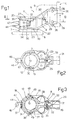
- a device for the articulated fastening of a rear-view mirror 4 to an automobile vehicle structure, for instance a bracket 6, is shown overall by 5.
- the mirror 4 and the bracket 6 do not form part of the fastening device 5 and are shown diagrammatically in dashed lines in Fig. 1.
- the fastening device 5 substantially comprises a fixed tubular member 7 connected to the bracket 6 and a moving member 8 connected to a portion 9 of a support for the mirror 4 also shown in dashed lines.
- the moving member 8 is connected to the fixed member 7 in an articulated manner about a single axis of rotation 11.
- the two members 7 and 8 are each made in one piece, by injection of a thermoplastic material in a corresponding mould, as a result of which their relative weight and manufacturing cost are substantially reduced.
- one of the two members 7, 8 is provided with at least one elastically deformable shaped member 12 adapted to be engaged in at least one seat 13 borne by the other of the two members 7, 8, in order to define an angular reference position of the mirror 4 with respect to the fixed member 7.
- the fixed member 7 in particular comprises a cylindrical upper portion 16 (Fig. 4) and a cylindrical lower portion 17, between which an intermediate portion 18 of smaller diameter is disposed.
- the portion 18 bears at least one pair of diametrically opposite seats 13 (Fig. 3), each of which is formed by an axial groove disposed between two ribs 19 (Fig. 3) of the portion 18.
- the fixed member 7 is further provided with two, respectively upper 20 and lower 22, flanges adjacent to the two cylindrical portions 16 and 17 and on opposite sides with respect thereto.
- the upper flange 20 is provided with a rounded edge 21, while the lower flange 22 is rigid with a connection base 23.
- the base 23 (Fig. 5) has a substantially prismatic shape and is triangular in cross-section, with rounded corners. At each corner, the base 23 is provided with a relative inner radial depression 26 and a relative hole 24 parallel to the axis 11 for connection to the bracket 6, in a manner that is known and not described in detail.
- the moving member 8 (Figs. 3 and 6) is formed by a sleeve 27 open along one of its generatrices, in order to form a slot 28.
- a pair of radial arms 29 start from both ends of the slot 28 in order to form a closeable clamp.
- the sleeve 27 is bounded at the top and the bottom by two projecting edges 30.
- the arms 29 (Fig. 1) are upwardly inclined and each have at their end a box-shaped portion 31.
- the two portions 31 are adapted to mesh when the two arms 29 are urged against one another.
- One of the two arms 29 is further provided with a hole 32 (Figs. 1 and 2) in which a connection screw 33 may be engaged, while the other arm 29 is provided with a hole 35, in which the screw 33 may be screwed to connect the arms 29 and close the moving member 8.
- the moving member 8 of the fastening device 5 is further provided with shaped members 12, which are adapted to bend elastically and are obtained rigidly with the sleeve 27.
- Each shaped member 12 is in particular formed by a curved elastic arm 34, ending in a projection 36 adapted to engage the seat 13.
- the two elastic arms 34 extend peripherally from a longitudinal portion 37 opposite to the slot 28 and are symmetrical to one another with respect to a median plane passing through the axis 11.
- the two projections 36 are diametrically opposite with respect to the axis 11.
- Each arm 29 of the moving member 8 is provided with a plurality of holes for the fastening of the support 9 of the mirror 4, in a known manner that is not described in detail.
- each arm 29 is provided with two pairs of horizontal holes 38 and 39 (Fig. 1) which are obtained through the box-shaped portions 31.
- the moving member 8 is also provided with a radial projection 44, disposed between the two elastic arms 34 and rigid with the longitudinal portion 37.
- the projection 44 is provided with an axial hole 46, which, with the holes 38 or 39, is used to fasten the moving member 8 to the body of the rear-view mirror.
- the longitudinal portion 37 is provided with two radial pins 47 for the positioning of a possible auxiliary spring 48 for the curved elastic arms 34.
- the spring 48 shown diagrammatically and partially in Fig. 3, is preferably of metal and of the * type and has a pair of facing portions 49, each of which acts on a relative outwardly flared cavity 51 of the projection 36 of the corresponding elastic arm 34.
- the fastening device 5 operates as follows.
- the sleeve 27 In order to mount the moving member 8 of the device 5 on the fixed member 7, the sleeve 27 is moved apart and is inserted with its edges 30 (Fig. 1) between the two flanges 20 and 22 of the fixed member 7. When the arms 29 are closed by means of the screw 33, the sleeve 27 is axially locked between the two flanges 20 and 22 which prevent it from sliding axially with respect to the fixed member 7. In this way, the sleeve 27 engages the two cylindrical portions 16 and 17, while the two elastic arms 34 engage the intermediate portion 18.
- the moving member 8 is rotated on the fixed member 7 until the projections 36 of the elastic arms 34 of the moving member 8 snap-lock on the seats 13 of the fixed member 7.
- the bending strength of the arms 34 makes it possible to define an angular reference position of the moving member 8 and, therefore, of the rear-view mirror 4, with respect to the fixed member 7 about the axis of rotation 11 of the articulation.
- the projections 36 come out of the seats 13.
- the driver acting on the body of the rear-view mirror connected to the projection 46, may rotate the moving member 8 on the fixed member 7 until the projections 36 again snap-lock with the seats 13.
- the *-shaped spring 48 (Fig. 3) may be coupled between the pins 47 of the longitudinal portion 37.
- the spring 48 by engaging its facing portions 49 in the cavities 51 of the projections 36, increases the resistant couple of the arms 34.
- both the fixed member 7 and the moving member 8 may be each obtained as a single component by moulding of a thermoplastic material, as a result of which the device 5 is of smaller weight and cost. This material can also be readily recycled, in the case of wastage.
- the fastening device 5 makes it possible to add additional elastic members, in order to regulate the couple resistant to the rotation of the moving member 8.
Landscapes
- Engineering & Computer Science (AREA)
- Multimedia (AREA)
- Mechanical Engineering (AREA)
- Rear-View Mirror Devices That Are Mounted On The Exterior Of The Vehicle (AREA)
Applications Claiming Priority (2)
| Application Number | Priority Date | Filing Date | Title |
|---|---|---|---|
| ITTO981030 | 1998-12-09 | ||
| IT1998TO001030A IT1303573B1 (it) | 1998-12-09 | 1998-12-09 | Dispositivo di fissaggio a snodo di uno specchio retrovisore esternosu una struttura di un autoveicolo. |
Publications (2)
| Publication Number | Publication Date |
|---|---|
| EP1008488A1 true EP1008488A1 (de) | 2000-06-14 |
| EP1008488B1 EP1008488B1 (de) | 2003-05-14 |
Family
ID=11417234
Family Applications (1)
| Application Number | Title | Priority Date | Filing Date |
|---|---|---|---|
| EP99124415A Expired - Lifetime EP1008488B1 (de) | 1998-12-09 | 1999-12-07 | Vorrichtung zur gelenkigen Befestigung eines Aussenrückblickspiegels an einer Kraftfahrzeugstruktur |
Country Status (4)
| Country | Link |
|---|---|
| EP (1) | EP1008488B1 (de) |
| DE (1) | DE69907855T2 (de) |
| ES (1) | ES2196709T3 (de) |
| IT (1) | IT1303573B1 (de) |
Cited By (1)
| Publication number | Priority date | Publication date | Assignee | Title |
|---|---|---|---|---|
| WO2007031069A3 (de) * | 2005-09-12 | 2007-06-07 | Schefenacker Engelmann Spiegel | Verstellbarer spiegel |
Citations (3)
| Publication number | Priority date | Publication date | Assignee | Title |
|---|---|---|---|---|
| EP0531944A1 (de) * | 1991-09-10 | 1993-03-17 | GILARDINI S.p.A. | Aussenrückblickspiegel für ein Kraftfahrzeug |
| WO1996014221A1 (en) * | 1994-11-02 | 1996-05-17 | United Technologies Automotive Systems, Inc. | Pivot mount for exterior side-mounted rearview mirror |
| DE29621153U1 (de) * | 1996-12-05 | 1998-04-02 | Hohe GmbH & Co. KG, 97903 Collenberg | Außenspiegelgelenk |
-
1998
- 1998-12-09 IT IT1998TO001030A patent/IT1303573B1/it active IP Right Grant
-
1999
- 1999-12-07 EP EP99124415A patent/EP1008488B1/de not_active Expired - Lifetime
- 1999-12-07 DE DE69907855T patent/DE69907855T2/de not_active Expired - Fee Related
- 1999-12-07 ES ES99124415T patent/ES2196709T3/es not_active Expired - Lifetime
Patent Citations (3)
| Publication number | Priority date | Publication date | Assignee | Title |
|---|---|---|---|---|
| EP0531944A1 (de) * | 1991-09-10 | 1993-03-17 | GILARDINI S.p.A. | Aussenrückblickspiegel für ein Kraftfahrzeug |
| WO1996014221A1 (en) * | 1994-11-02 | 1996-05-17 | United Technologies Automotive Systems, Inc. | Pivot mount for exterior side-mounted rearview mirror |
| DE29621153U1 (de) * | 1996-12-05 | 1998-04-02 | Hohe GmbH & Co. KG, 97903 Collenberg | Außenspiegelgelenk |
Cited By (1)
| Publication number | Priority date | Publication date | Assignee | Title |
|---|---|---|---|---|
| WO2007031069A3 (de) * | 2005-09-12 | 2007-06-07 | Schefenacker Engelmann Spiegel | Verstellbarer spiegel |
Also Published As
| Publication number | Publication date |
|---|---|
| ITTO981030A1 (it) | 2000-06-09 |
| EP1008488B1 (de) | 2003-05-14 |
| DE69907855T2 (de) | 2004-03-11 |
| ES2196709T3 (es) | 2003-12-16 |
| DE69907855D1 (de) | 2003-06-18 |
| IT1303573B1 (it) | 2000-11-14 |
| ITTO981030A0 (it) | 1998-12-09 |
Similar Documents
| Publication | Publication Date | Title |
|---|---|---|
| EP0737138B1 (de) | Drehverbindung für einen seitlichen aussenrückblickspiegel | |
| US7798551B2 (en) | Vehicle-mountable sun visor | |
| JPH0761286A (ja) | 自動車用離脱式アクセサリー取付装置 | |
| US20020001148A1 (en) | Pivoting outside mirror for a motor vehicle | |
| EP2006134A1 (de) | Fahrzeugtür | |
| JP2005138831A (ja) | 車両ミラー用支持アーム | |
| US20060087754A1 (en) | Rear view mirror with snap connection | |
| US5726816A (en) | Reversible rearview mirror | |
| US6290287B1 (en) | Structural element with at least a headlamp, and method for mounting such an assembly in a motor vehicle body | |
| EP1008488A1 (de) | Vorrichtung zur gelenkigen Befestigung eines Aussenrückblickspiegels an einer Kraftfahrzeugstruktur | |
| US20100224753A1 (en) | Mounting Construction for an Outside Mirror Unit | |
| KR100695774B1 (ko) | 상용차 외측 미러로서의 후사경 | |
| US7172237B2 (en) | High rotation angle for gas spring connection | |
| US8118529B2 (en) | Tolerance adjusting attachment | |
| JP7646600B2 (ja) | 可動軸のロック機構、可動軸、及び人形玩具 | |
| JP2022130843A (ja) | 車両用外装部品 | |
| US4732461A (en) | External rearview mirror with releasable catch mechanism for motor vehicles | |
| KR102568039B1 (ko) | 자동차의 외부 시야 유닛의 운반 프레임에 외부 거울, 카메라 및/또는 디스플레이와 같은 외부 시야 요소를 위한 조정 기구를 체결하기 위한 체결 구조와, 외부 시야 유닛 | |
| US4755024A (en) | Rearview mirror | |
| JP2001056070A (ja) | ブラケット係止用クランプ | |
| CN223014415U (zh) | 高稳定性增强型儿童安全座椅支撑腿连接系统 | |
| EP1013502A1 (de) | Aussenrückblickspiegel für Kraftfahrzeuge, insbesondere Nutzfahrzeuge | |
| JP2524068Y2 (ja) | 自動車ヘッドランプの取付装置 | |
| EP3225467B1 (de) | Fahrzeugspiegel und verfahren zu dessen herstellung | |
| JP3677777B2 (ja) | ギア取り付け構造およびそれを備えたプリンタ |
Legal Events
| Date | Code | Title | Description |
|---|---|---|---|
| PUAI | Public reference made under article 153(3) epc to a published international application that has entered the european phase |
Free format text: ORIGINAL CODE: 0009012 |
|
| AK | Designated contracting states |
Kind code of ref document: A1 Designated state(s): DE ES FR GB |
|
| AX | Request for extension of the european patent |
Free format text: AL;LT;LV;MK;RO;SI |
|
| 17P | Request for examination filed |
Effective date: 20000617 |
|
| AKX | Designation fees paid |
Free format text: DE ES FR GB |
|
| 17Q | First examination report despatched |
Effective date: 20010920 |
|
| GRAG | Despatch of communication of intention to grant |
Free format text: ORIGINAL CODE: EPIDOS AGRA |
|
| GRAG | Despatch of communication of intention to grant |
Free format text: ORIGINAL CODE: EPIDOS AGRA |
|
| GRAH | Despatch of communication of intention to grant a patent |
Free format text: ORIGINAL CODE: EPIDOS IGRA |
|
| RAP1 | Party data changed (applicant data changed or rights of an application transferred) |
Owner name: FICOMIRRORS ITALIA S.R.L. A S.U. |
|
| GRAH | Despatch of communication of intention to grant a patent |
Free format text: ORIGINAL CODE: EPIDOS IGRA |
|
| GRAA | (expected) grant |
Free format text: ORIGINAL CODE: 0009210 |
|
| AK | Designated contracting states |
Designated state(s): DE ES FR GB |
|
| REG | Reference to a national code |
Ref country code: GB Ref legal event code: FG4D |
|
| REF | Corresponds to: |
Ref document number: 69907855 Country of ref document: DE Date of ref document: 20030618 Kind code of ref document: P |
|
| REG | Reference to a national code |
Ref country code: ES Ref legal event code: FG2A Ref document number: 2196709 Country of ref document: ES Kind code of ref document: T3 |
|
| ET | Fr: translation filed | ||
| PLBE | No opposition filed within time limit |
Free format text: ORIGINAL CODE: 0009261 |
|
| STAA | Information on the status of an ep patent application or granted ep patent |
Free format text: STATUS: NO OPPOSITION FILED WITHIN TIME LIMIT |
|
| 26N | No opposition filed |
Effective date: 20040217 |
|
| PGFP | Annual fee paid to national office [announced via postgrant information from national office to epo] |
Ref country code: FR Payment date: 20041029 Year of fee payment: 6 |
|
| PGFP | Annual fee paid to national office [announced via postgrant information from national office to epo] |
Ref country code: ES Payment date: 20041117 Year of fee payment: 6 |
|
| PGFP | Annual fee paid to national office [announced via postgrant information from national office to epo] |
Ref country code: GB Payment date: 20041201 Year of fee payment: 6 |
|
| PGFP | Annual fee paid to national office [announced via postgrant information from national office to epo] |
Ref country code: DE Payment date: 20041227 Year of fee payment: 6 |
|
| PG25 | Lapsed in a contracting state [announced via postgrant information from national office to epo] |
Ref country code: GB Free format text: LAPSE BECAUSE OF NON-PAYMENT OF DUE FEES Effective date: 20051207 |
|
| PG25 | Lapsed in a contracting state [announced via postgrant information from national office to epo] |
Ref country code: ES Free format text: LAPSE BECAUSE OF NON-PAYMENT OF DUE FEES Effective date: 20051209 |
|
| PG25 | Lapsed in a contracting state [announced via postgrant information from national office to epo] |
Ref country code: DE Free format text: LAPSE BECAUSE OF NON-PAYMENT OF DUE FEES Effective date: 20060701 |
|
| GBPC | Gb: european patent ceased through non-payment of renewal fee |
Effective date: 20051207 |
|
| PG25 | Lapsed in a contracting state [announced via postgrant information from national office to epo] |
Ref country code: FR Free format text: LAPSE BECAUSE OF NON-PAYMENT OF DUE FEES Effective date: 20060831 |
|
| REG | Reference to a national code |
Ref country code: FR Ref legal event code: ST Effective date: 20060831 |
|
| REG | Reference to a national code |
Ref country code: ES Ref legal event code: FD2A Effective date: 20051209 |