EP1008559A1 - Procédé de traitement des déchets d'origine animale - Google Patents
Procédé de traitement des déchets d'origine animale Download PDFInfo
- Publication number
- EP1008559A1 EP1008559A1 EP99301081A EP99301081A EP1008559A1 EP 1008559 A1 EP1008559 A1 EP 1008559A1 EP 99301081 A EP99301081 A EP 99301081A EP 99301081 A EP99301081 A EP 99301081A EP 1008559 A1 EP1008559 A1 EP 1008559A1
- Authority
- EP
- European Patent Office
- Prior art keywords
- water
- filter
- stream
- sludge
- treated
- Prior art date
- Legal status (The legal status is an assumption and is not a legal conclusion. Google has not performed a legal analysis and makes no representation as to the accuracy of the status listed.)
- Withdrawn
Links
- 238000000034 method Methods 0.000 title claims abstract description 38
- 239000010828 animal waste Substances 0.000 title description 7
- IJGRMHOSHXDMSA-UHFFFAOYSA-N Atomic nitrogen Chemical compound N#N IJGRMHOSHXDMSA-UHFFFAOYSA-N 0.000 claims abstract description 50
- 239000010802 sludge Substances 0.000 claims abstract description 39
- 239000002699 waste material Substances 0.000 claims abstract description 35
- 244000052769 pathogen Species 0.000 claims abstract description 32
- 230000008569 process Effects 0.000 claims abstract description 28
- 229910052757 nitrogen Inorganic materials 0.000 claims abstract description 25
- 241001465754 Metazoa Species 0.000 claims abstract description 24
- 239000000654 additive Substances 0.000 claims abstract description 10
- 230000000996 additive effect Effects 0.000 claims abstract description 10
- 239000007788 liquid Substances 0.000 claims abstract description 8
- XLYOFNOQVPJJNP-UHFFFAOYSA-N water Substances O XLYOFNOQVPJJNP-UHFFFAOYSA-N 0.000 claims description 102
- 239000007787 solid Substances 0.000 claims description 29
- 239000003651 drinking water Substances 0.000 claims description 22
- 230000001717 pathogenic effect Effects 0.000 claims description 21
- 235000012206 bottled water Nutrition 0.000 claims description 10
- 239000002245 particle Substances 0.000 claims description 10
- 238000001914 filtration Methods 0.000 claims description 8
- 150000002829 nitrogen Chemical class 0.000 claims description 7
- 239000002351 wastewater Substances 0.000 claims description 5
- 239000000047 product Substances 0.000 claims description 4
- 239000000356 contaminant Substances 0.000 claims description 3
- 239000012265 solid product Substances 0.000 claims 2
- 238000011001 backwashing Methods 0.000 claims 1
- CBENFWSGALASAD-UHFFFAOYSA-N Ozone Chemical compound [O-][O+]=O CBENFWSGALASAD-UHFFFAOYSA-N 0.000 abstract description 4
- ZAMOUSCENKQFHK-UHFFFAOYSA-N Chlorine atom Chemical compound [Cl] ZAMOUSCENKQFHK-UHFFFAOYSA-N 0.000 abstract description 2
- QVGXLLKOCUKJST-UHFFFAOYSA-N atomic oxygen Chemical compound [O] QVGXLLKOCUKJST-UHFFFAOYSA-N 0.000 description 15
- 239000001301 oxygen Substances 0.000 description 15
- 229910052760 oxygen Inorganic materials 0.000 description 15
- 235000020188 drinking water Nutrition 0.000 description 12
- QGZKDVFQNNGYKY-UHFFFAOYSA-N Ammonia Chemical compound N QGZKDVFQNNGYKY-UHFFFAOYSA-N 0.000 description 9
- 238000012360 testing method Methods 0.000 description 9
- OAICVXFJPJFONN-UHFFFAOYSA-N Phosphorus Chemical compound [P] OAICVXFJPJFONN-UHFFFAOYSA-N 0.000 description 8
- 229910052698 phosphorus Inorganic materials 0.000 description 8
- 239000011574 phosphorus Substances 0.000 description 8
- 241000282887 Suidae Species 0.000 description 7
- 238000005273 aeration Methods 0.000 description 7
- 241000894006 Bacteria Species 0.000 description 6
- XKMRRTOUMJRJIA-UHFFFAOYSA-N ammonia nh3 Chemical compound N.N XKMRRTOUMJRJIA-UHFFFAOYSA-N 0.000 description 6
- 239000012530 fluid Substances 0.000 description 6
- 230000005484 gravity Effects 0.000 description 6
- 229910002651 NO3 Inorganic materials 0.000 description 5
- NHNBFGGVMKEFGY-UHFFFAOYSA-N Nitrate Chemical compound [O-][N+]([O-])=O NHNBFGGVMKEFGY-UHFFFAOYSA-N 0.000 description 5
- 230000008901 benefit Effects 0.000 description 5
- 239000003337 fertilizer Substances 0.000 description 5
- 239000000126 substance Substances 0.000 description 5
- 239000006228 supernatant Substances 0.000 description 5
- OKTJSMMVPCPJKN-UHFFFAOYSA-N Carbon Chemical compound [C] OKTJSMMVPCPJKN-UHFFFAOYSA-N 0.000 description 4
- IOVCWXUNBOPUCH-UHFFFAOYSA-M Nitrite anion Chemical compound [O-]N=O IOVCWXUNBOPUCH-UHFFFAOYSA-M 0.000 description 4
- 229910021529 ammonia Inorganic materials 0.000 description 4
- 229910052799 carbon Inorganic materials 0.000 description 4
- 230000002262 irrigation Effects 0.000 description 4
- 238000003973 irrigation Methods 0.000 description 4
- 239000000203 mixture Substances 0.000 description 4
- 150000002823 nitrates Chemical class 0.000 description 4
- 150000002826 nitrites Chemical class 0.000 description 4
- 239000010865 sewage Substances 0.000 description 4
- 241000282898 Sus scrofa Species 0.000 description 3
- 208000021017 Weight Gain Diseases 0.000 description 3
- 238000005660 chlorination reaction Methods 0.000 description 3
- 238000010586 diagram Methods 0.000 description 3
- 230000029087 digestion Effects 0.000 description 3
- 238000005516 engineering process Methods 0.000 description 3
- 230000007613 environmental effect Effects 0.000 description 3
- 210000003608 fece Anatomy 0.000 description 3
- 230000006872 improvement Effects 0.000 description 3
- 238000012544 monitoring process Methods 0.000 description 3
- 235000019645 odor Nutrition 0.000 description 3
- 238000003860 storage Methods 0.000 description 3
- -1 that is Substances 0.000 description 3
- 210000002700 urine Anatomy 0.000 description 3
- 230000004584 weight gain Effects 0.000 description 3
- 235000019786 weight gain Nutrition 0.000 description 3
- PXHVJJICTQNCMI-UHFFFAOYSA-N Nickel Chemical compound [Ni] PXHVJJICTQNCMI-UHFFFAOYSA-N 0.000 description 2
- 241001148470 aerobic bacillus Species 0.000 description 2
- VSCWAEJMTAWNJL-UHFFFAOYSA-K aluminium trichloride Chemical compound Cl[Al](Cl)Cl VSCWAEJMTAWNJL-UHFFFAOYSA-K 0.000 description 2
- 238000006243 chemical reaction Methods 0.000 description 2
- 238000009792 diffusion process Methods 0.000 description 2
- 239000003344 environmental pollutant Substances 0.000 description 2
- 239000008394 flocculating agent Substances 0.000 description 2
- 238000009472 formulation Methods 0.000 description 2
- 239000013505 freshwater Substances 0.000 description 2
- 230000004941 influx Effects 0.000 description 2
- 238000009434 installation Methods 0.000 description 2
- 229910052751 metal Inorganic materials 0.000 description 2
- 239000002184 metal Substances 0.000 description 2
- VNWKTOKETHGBQD-UHFFFAOYSA-N methane Chemical compound C VNWKTOKETHGBQD-UHFFFAOYSA-N 0.000 description 2
- 244000005700 microbiome Species 0.000 description 2
- 230000001473 noxious effect Effects 0.000 description 2
- 231100000719 pollutant Toxicity 0.000 description 2
- 239000002243 precursor Substances 0.000 description 2
- 238000004064 recycling Methods 0.000 description 2
- 230000009467 reduction Effects 0.000 description 2
- 238000000926 separation method Methods 0.000 description 2
- 238000004065 wastewater treatment Methods 0.000 description 2
- 241000251468 Actinopterygii Species 0.000 description 1
- VYZAMTAEIAYCRO-UHFFFAOYSA-N Chromium Chemical compound [Cr] VYZAMTAEIAYCRO-UHFFFAOYSA-N 0.000 description 1
- RYGMFSIKBFXOCR-UHFFFAOYSA-N Copper Chemical compound [Cu] RYGMFSIKBFXOCR-UHFFFAOYSA-N 0.000 description 1
- 241000195493 Cryptophyta Species 0.000 description 1
- 208000012868 Overgrowth Diseases 0.000 description 1
- 239000011398 Portland cement Substances 0.000 description 1
- HCHKCACWOHOZIP-UHFFFAOYSA-N Zinc Chemical compound [Zn] HCHKCACWOHOZIP-UHFFFAOYSA-N 0.000 description 1
- 238000003916 acid precipitation Methods 0.000 description 1
- 230000004913 activation Effects 0.000 description 1
- 238000005276 aerator Methods 0.000 description 1
- WYTGDNHDOZPMIW-RCBQFDQVSA-N alstonine Natural products C1=CC2=C3C=CC=CC3=NC2=C2N1C[C@H]1[C@H](C)OC=C(C(=O)OC)[C@H]1C2 WYTGDNHDOZPMIW-RCBQFDQVSA-N 0.000 description 1
- DIZPMCHEQGEION-UHFFFAOYSA-H aluminium sulfate (anhydrous) Chemical compound [Al+3].[Al+3].[O-]S([O-])(=O)=O.[O-]S([O-])(=O)=O.[O-]S([O-])(=O)=O DIZPMCHEQGEION-UHFFFAOYSA-H 0.000 description 1
- 230000001580 bacterial effect Effects 0.000 description 1
- 238000007664 blowing Methods 0.000 description 1
- 230000005587 bubbling Effects 0.000 description 1
- 229910052793 cadmium Inorganic materials 0.000 description 1
- BDOSMKKIYDKNTQ-UHFFFAOYSA-N cadmium atom Chemical compound [Cd] BDOSMKKIYDKNTQ-UHFFFAOYSA-N 0.000 description 1
- 150000001722 carbon compounds Chemical class 0.000 description 1
- 238000004182 chemical digestion Methods 0.000 description 1
- 239000007795 chemical reaction product Substances 0.000 description 1
- 239000002894 chemical waste Substances 0.000 description 1
- 239000000460 chlorine Substances 0.000 description 1
- 229910052801 chlorine Inorganic materials 0.000 description 1
- 229910052804 chromium Inorganic materials 0.000 description 1
- 239000011651 chromium Substances 0.000 description 1
- 239000000701 coagulant Substances 0.000 description 1
- 230000003750 conditioning effect Effects 0.000 description 1
- 229910052802 copper Inorganic materials 0.000 description 1
- 239000010949 copper Substances 0.000 description 1
- 229910000365 copper sulfate Inorganic materials 0.000 description 1
- ARUVKPQLZAKDPS-UHFFFAOYSA-L copper(II) sulfate Chemical compound [Cu+2].[O-][S+2]([O-])([O-])[O-] ARUVKPQLZAKDPS-UHFFFAOYSA-L 0.000 description 1
- 235000013365 dairy product Nutrition 0.000 description 1
- 230000001419 dependent effect Effects 0.000 description 1
- 239000000645 desinfectant Substances 0.000 description 1
- 238000011161 development Methods 0.000 description 1
- QGBQVPDZYFBQSM-UHFFFAOYSA-J diazanium;disodium;zinc;boric acid;hydroxy-(hydroxy(dioxo)chromio)oxy-dioxochromium;dichloride;sulfate;dihydrate Chemical compound [NH4+].[NH4+].O.O.[Na+].[Na+].[Cl-].[Cl-].[Zn+2].OB(O)O.[O-]S([O-])(=O)=O.O[Cr](=O)(=O)O[Cr](O)(=O)=O QGBQVPDZYFBQSM-UHFFFAOYSA-J 0.000 description 1
- 229910001873 dinitrogen Inorganic materials 0.000 description 1
- 201000010099 disease Diseases 0.000 description 1
- 208000037265 diseases, disorders, signs and symptoms Diseases 0.000 description 1
- 238000006073 displacement reaction Methods 0.000 description 1
- 239000010791 domestic waste Substances 0.000 description 1
- 230000035622 drinking Effects 0.000 description 1
- 238000001035 drying Methods 0.000 description 1
- 230000000694 effects Effects 0.000 description 1
- 238000001704 evaporation Methods 0.000 description 1
- 230000008020 evaporation Effects 0.000 description 1
- 238000002474 experimental method Methods 0.000 description 1
- 230000002550 fecal effect Effects 0.000 description 1
- 239000000706 filtrate Substances 0.000 description 1
- 238000011010 flushing procedure Methods 0.000 description 1
- 239000007789 gas Substances 0.000 description 1
- 230000002070 germicidal effect Effects 0.000 description 1
- 239000003864 humus Substances 0.000 description 1
- 239000002440 industrial waste Substances 0.000 description 1
- 239000010842 industrial wastewater Substances 0.000 description 1
- 238000002347 injection Methods 0.000 description 1
- 239000007924 injection Substances 0.000 description 1
- 239000003621 irrigation water Substances 0.000 description 1
- 239000010808 liquid waste Substances 0.000 description 1
- 238000012423 maintenance Methods 0.000 description 1
- 238000004519 manufacturing process Methods 0.000 description 1
- 239000000463 material Substances 0.000 description 1
- 230000007246 mechanism Effects 0.000 description 1
- 150000002739 metals Chemical class 0.000 description 1
- 230000004048 modification Effects 0.000 description 1
- 238000012986 modification Methods 0.000 description 1
- 239000010813 municipal solid waste Substances 0.000 description 1
- 229910052759 nickel Inorganic materials 0.000 description 1
- 235000021049 nutrient content Nutrition 0.000 description 1
- 235000015097 nutrients Nutrition 0.000 description 1
- 239000005416 organic matter Substances 0.000 description 1
- 239000007800 oxidant agent Substances 0.000 description 1
- 230000001590 oxidative effect Effects 0.000 description 1
- 238000006213 oxygenation reaction Methods 0.000 description 1
- 238000006385 ozonation reaction Methods 0.000 description 1
- 230000002572 peristaltic effect Effects 0.000 description 1
- 230000002085 persistent effect Effects 0.000 description 1
- 239000012286 potassium permanganate Substances 0.000 description 1
- 244000144977 poultry Species 0.000 description 1
- 239000000843 powder Substances 0.000 description 1
- 238000001556 precipitation Methods 0.000 description 1
- 238000000746 purification Methods 0.000 description 1
- 230000005855 radiation Effects 0.000 description 1
- 238000009877 rendering Methods 0.000 description 1
- 230000008439 repair process Effects 0.000 description 1
- 238000011160 research Methods 0.000 description 1
- 238000001223 reverse osmosis Methods 0.000 description 1
- 239000000523 sample Substances 0.000 description 1
- 239000002002 slurry Substances 0.000 description 1
- 239000002910 solid waste Substances 0.000 description 1
- 239000000243 solution Substances 0.000 description 1
- 241001148471 unidentified anaerobic bacterium Species 0.000 description 1
- 238000005406 washing Methods 0.000 description 1
- 230000003442 weekly effect Effects 0.000 description 1
- 229910052725 zinc Inorganic materials 0.000 description 1
- 239000011701 zinc Substances 0.000 description 1
Images


Classifications
-
- G—PHYSICS
- G11—INFORMATION STORAGE
- G11B—INFORMATION STORAGE BASED ON RELATIVE MOVEMENT BETWEEN RECORD CARRIER AND TRANSDUCER
- G11B33/00—Constructional parts, details or accessories not provided for in the other groups of this subclass
- G11B33/14—Reducing influence of physical parameters, e.g. temperature change, moisture, dust
- G11B33/1446—Reducing contamination, e.g. by dust, debris
- G11B33/146—Reducing contamination, e.g. by dust, debris constructional details of filters
-
- C—CHEMISTRY; METALLURGY
- C02—TREATMENT OF WATER, WASTE WATER, SEWAGE, OR SLUDGE
- C02F—TREATMENT OF WATER, WASTE WATER, SEWAGE, OR SLUDGE
- C02F3/00—Biological treatment of water, waste water, or sewage
- C02F3/30—Aerobic and anaerobic processes
- C02F3/302—Nitrification and denitrification treatment
-
- C—CHEMISTRY; METALLURGY
- C02—TREATMENT OF WATER, WASTE WATER, SEWAGE, OR SLUDGE
- C02F—TREATMENT OF WATER, WASTE WATER, SEWAGE, OR SLUDGE
- C02F9/00—Multistage treatment of water, waste water or sewage
-
- C—CHEMISTRY; METALLURGY
- C02—TREATMENT OF WATER, WASTE WATER, SEWAGE, OR SLUDGE
- C02F—TREATMENT OF WATER, WASTE WATER, SEWAGE, OR SLUDGE
- C02F1/00—Treatment of water, waste water, or sewage
- C02F1/72—Treatment of water, waste water, or sewage by oxidation
- C02F1/76—Treatment of water, waste water, or sewage by oxidation with halogens or compounds of halogens
-
- C—CHEMISTRY; METALLURGY
- C02—TREATMENT OF WATER, WASTE WATER, SEWAGE, OR SLUDGE
- C02F—TREATMENT OF WATER, WASTE WATER, SEWAGE, OR SLUDGE
- C02F1/00—Treatment of water, waste water, or sewage
- C02F1/72—Treatment of water, waste water, or sewage by oxidation
- C02F1/78—Treatment of water, waste water, or sewage by oxidation with ozone
-
- C—CHEMISTRY; METALLURGY
- C02—TREATMENT OF WATER, WASTE WATER, SEWAGE, OR SLUDGE
- C02F—TREATMENT OF WATER, WASTE WATER, SEWAGE, OR SLUDGE
- C02F2103/00—Nature of the water, waste water, sewage or sludge to be treated
- C02F2103/20—Nature of the water, waste water, sewage or sludge to be treated from animal husbandry
Definitions
- the present invention relates generally to the field of animal waste treatment, specifically the treatment of solid and liquid waste from agricultural sites. More specifically, it relates to an improved device and process for treating a waste stream in a closed loop system without using an open-air pond, or lagoon.
- the process yields solids that can be captured and processed as fertilizer as well as wash water for the animal pens, water for other purposes such as irrigation, and, optionally, potable drinking water for the animals.
- Raising animals has become a big business.
- North Carolina alone for example, the poultry, swine and dairy businesses are worth about $4 billion annually, and employ at least about 40,000 people directly. This translates into about 4,000 farms in North Carolina alone having facilities devoted to swine, each of which must conform to the appropriate environmental regulations.
- the present technological standard is a system utilizing an anaerobic lagoon, and most facilities are so equipped. While these systems do act to contain much of the waste, they leave something to be desired.
- a typical lagoon system would be described as follows: the farm has several barns which have floors made of slats and a collection basin under each building. The animals are housed in the barns, and their feces, slops, urine and spilled drinking water fall through the slats into the collection basin. Each barn also has two 1,500-3,000 liter flush tanks. Every three to six hours, about 3,000 -1,600 liters of water per barn are dumped into the collection basin, which washes the waste by gravity feed to an anaerobic lagoon.
- Such a system is described in United States Patent No. 4,913,095, "Flushing System for Hog Houses", issued to Morrow, et al. April 3, 1990.
- the flush tanks are then refilled using water from the top of the lagoon.
- a pit-recharge system about 0.6m of water is kept under the barn in an enlarged version of the collection basin. This pit has an outlet which is opened on a weekly basis to allow the water to drain to an anaerobic lagoon. The pit is then refilled using water from the lagoon.
- the solids in a lagoon settle out and are anaerobically digested over time by benign bacteria. After a certain amount of time, the top layer of water is purified enough to allow it to be drawn off and reused, either as wash water, or as water for crops.
- the quality of the water drawn off is not good enough to make it useable for all crops, and when the water is sprinkled on a field, it releases noxious odors.
- the quality of water is not good enough to be used as drinking water for the animals, so there is a steady addition of water to the system due to the spillage from the fresh water system as well as water in the form of urine and feces from the animals.
- the rate of evaporation and draw-off of water are often less than the rate of influx of water as well as solids into the lagoon. As a result, the lagoon gradually fills up.
- a typical lagoon might be 4m deep and contain about 3 m 3 of water, and 1200 tonnes of solids. Such a lagoon also contains a large amount of ammonia, nitrates, nitrites and phosphorus, and may on occasion contain disease-causing bacteria. If rainfall is unusually heavy, or if the liner for the lagoon cracks, significant amounts of pollutants can be released, possibly rendering water wells on neighboring land unfit for use, causing an overgrowth of algae in runoff streams, or even resulting in fish kills in rivers. Lagoons release noxious odors into the air, and have been associated with acid rain.
- United States Patent No. 4,121,539 "Animal Enclosure System with Waste Treatment Means" issued October 24, 1978 to Moore relates to a lagoon system that additionally uses airtight holding tanks for a waste stream, the first producing ammonia gas at ambient temperatures and the second for further digestion of the waste, where methane gas is produced.
- the present inventor has developed a lagoon-less system, which is a precursor for the present invention, for recycling waste from animal houses which greatly improves the water quality of the effluent over that typically found in lagoon systems, variations of this system are disclosed below in Figs. 2 and 3, and the discussion therewith.
- This is a closed loop system that utilizes aerobic bacteria. As such, the system still requires an air supply, bacteria, and extended residence time in a holding tank. Due the presence of bacteria as an integral part of the system, licensed operators are required to monitor the system at least daily. Further, the closed loop system as disclosed in Figs. 2 and 3 is much larger than the present invention, requires installation of permanent fixtures at the site, and would require further modification to produce potable water.
- the present invention relates to an improved device and process for treating animal waste that is a closed loop system which yields water with greatly reduced carbon and nitrogen levels, and optionally, potable drinking water, plus solids that may be processed as fertilizer.
- the system does not require a lagoon or the addition of permanent structures to the land. It is relatively simple to monitor, and amenable to an electronic control system. It can produce a healthier environment for animals, and thereby increase profitability to the farmer.
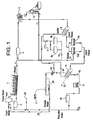
- an animal house or production building (1) is equipped with one or more storage tanks for recycled water, or flush tanks (2) and connected to a waste water storage tank, or equalization tank, (3) by a gravity feed line (4).
- Animal waste drops through slats in the floor of the house (1) into a pit (not shown) that is periodically flushed by water from the flush tank (2), which flows by way of the gravity feed line (4) to the equalization tank (3).
- the waste stream is pumped to a separator, illustrated here as a two-step process using inclined screen separator (5 ) and roller press separator (6). While separators (5) and (6) are shown as separated devices, it is contemplated that they can be combined into a single separation unit.
- Solids are separated from the waste stream by the separators (5 and 6) and may be further treated to yield other end products, for example, various classes of fertilizer.
- the water, or effluent pressed from the solids at the second separator (6) is returned to the equaliztion tank (3) by return flow line (7).
- Some of the water, or effluent, from the separators (5 and 6) is pumped to a first filter (8). If the filter (8) is an automatic backwash filter, the backwash, or sludge, is pumped automatically to sludge holding tanks (9a,b). Sludge from tanks (9 a,b) is returned by sludge return line (10) to the equalization tank (3), or in the alternative (not shown) to the separators (5 and 6).
- the sludge tanks may be equipped with an additive reservoir (11).
- Sludge tanks (9a,b) are operated in tandem so that an additive from reservoir (11) can be injected into one tank as it fills, while the other tank allows the additive sufficient residence time to perform its function.
- the liquid filtrate from first filter (8) is subjected to a nitrogen removal, or nitrification/denitrification step at nitrogen treatment tanks (12 a,b).
- nitrogen treatment tanks (12 a,b) it is advantageous to use two tanks operated in tandem.
- Sludge that settles in these tanks (12 a,b) is returned to equalization tank (3) by sludge return line (13).
- the fluid stream from the nitrification or denitrification step is flowed to a second filter (14).
- the fluid stream from the second filter (14) is in excess of the amount that can be used by the flush system. The reason is that there is a steady influx of water from the drinking water system. The excess water can be treated and used for a variety of purposes. As a consequence, the fluid stream from the second filter (14) is split.
- a first filter feed line (15) leads to a first pathogen treatment tank (16), which, in this embodiment, is equipped with a chlorinator (17).
- the stream flowing from the first pathogen treatment tank (16) is pathogen-free wash water, and may be treated using an odor control injection system (24) before it feeds into the flush tank (2).
- a second filter feed line (18) feeds to a third filter (19) followed by a second pathogen treatment tank (20), which in this embodiment is equipped with an ozone treatment system (21).
- the fluid stream from the second pathogen treatment tank (20) is potable water, and may feed, for example, into the fresh water line (25) to drinking water tank (22).
- a third filter feed line (23) may be added to divert recycled water to certain non-demanding applications, such as irrigation.
- drinking water line (25) can be equipped with a valve system and a probe (neither shown) so that if the water exceeds a predetermined limit, the drinking water line (25) is shut off, and the water is recycled to the second pathogen treatment tank (20).
- Fig. 2 shows a similar arrangement with respect to animal houses (1a-d), flush tanks (2a-d), equalization tank (3) by a gravity feed line (4) and separator (5).
- solids are separated from the waste stream by the separator (5) and may be further treated to yield various classes of fertilizer.
- Some of the water, or effluent from the separator (5) is returned to the equaliztion tank (3) by return flow line (7) in order to maintain equilibrium flow from the equalization tank(3) to the separator (5).
- What effluent which is not returned to the equalization tank (3) is pumped to serpentine aeration tanks (30a-f which are equipped with air diffusers supplied by air blowers (not shown)), and then hopper clarifiers (31) which are equipped with return activated sludge line (32) which feeds to the separator (5) and waste sludge line (33) which feeds to sludge holding tank (34), as well as a weir, or trough with notches in it to control the water flow (not shown) at the top of the clarifier (31) which feeds to a line (38) to the supernatant holding tank (35).
- the supernatant holding tank (35) has a return line (36) which leads to the flush tanks (2).
- the sludge holding tank (34) has a return line (37) to the separator (5).
- Fig. 3 is a variation on the theme from Fig. 2, again showing equalization tank (3) connected by gravity feed line (4) to separator (5). Again, some of the water, or effluent, from the separator (5) is returned to the equaliztion tank (3) by return flow line (7) in order to maintain equilibrium flow from the equalization tank(3) to the separator (5). Effluent which is not returned to the equalization tank (3) is pumped through line (39) to a liquid aeration basin (40).
- the liquid aeration basin (40) is equipped with an air blowing system (41) connected by an air trunk line (42) having a set of several diffusion drops (43) into the basin (40).
- Air is flowed through the diffusion drops (43) and maintains circulation and activation of the effluent.
- Effluent from the aeration basin (40) is fed by effluent line (44) to a set of hopper clarifiers (45) which are equipped with a return activated sludge line (46) which feeds to the aeration basin (40), a waste sludge line (47) which feeds to a sludge holding tank (48), and supernatant line (49) which leads to a supernatant holding tank (50).
- the sludge holding tank (48) has an outlet line (51) to the separator (5).
- the supernatant holding tank (50) has an outlet line (52) which may lead to the flush tanks (2a,b), or to another utilization (53) such as a pond or field.
- a further object of this invention is to provide a method of treating animal waste that consistently yields potable water as an end result.
- It is yet a further object of this invention to provide a method of recycling water used in animal husbandry.
- Yet another object of this invention is to provide a method of reducing ammonia emissions as well as reducing phosphorus and nutrient content from agricultural sites to manageable levels.
- An even further object of this invention is to provide equipment for treating animal waste that need not be permanently installed.
- a waste treatment system for an animal husbandry site can be constructed so that a waste stream can be carried to an equalization tank sized for the particular site. From the equalization tank the waste is pumped to a separator. The liquid stream from the separator flows to a first filter, then a nitrogen remover, followed by a second filter. The stream from the second filter is suitable for use as recycled water for some applications such as irrigation. Where pathogen removal is desired, the stream from the second filter is pumped to a pathogen remover.
- the water stream can be split to produce a component which is flush water and subjected to one form of pathogen removal such a chlorination, and a second component which is subjected to a further filtering step and treated for biological contaminants to yield potable water, that is, drinking water.
- This water may be recycled to the animal husbandry site or discharged into a permitted stream.
- An advantage of the present invention is that it consistently yields water of improved quality with a minimum of skilled human monitoring.
- a further advantage is that the recycled water can improve the quality of life of the animals, as reflected in improved weight gains and shorter residence times in feeding facilities.
- Yet another advantage is that the entire waste treatment system requires a negligible amount of land to operate, and can be treated as an appliance instead of a fixture.
- Waste is washed from under the barns either from a flush tank system or pit recharge system.
- the waste stream enters a tank referred to herein as an equalization tank through pipes from each barn by gravity flow.
- the equalization tank is typically installed in the ground, and its size is determined by the volume of the barns' waste stream, which includes all waste material, including feces, urine, spillage, and washdown water.
- the equalization tank can be made of any number of materials known to those of ordinary skill in the art, including plastic, concrete, and metal.
- a pump is used to bring the waste stream from the equalization tank to the first stage of the present invention, a separator.
- the pump can be any type known to those of ordinary skill in the art, including a grinder, centrifugal, trash, diaphragm, peristaltic and air displacement pumps.
- the waste stream is pumped through a pipe sized according to the desired flow rate to a separator capable of removing large solids, that is, solids bigger than about 100 to 300 ⁇ m, from the waste stream.
- Suitable separators include filter presses, auger-type separators and other separators useful for large particles. Inclined screen and roller press separators such as those available from Key Dollar Co. Milton-Freewater, Oregon, are preferred. It is envisioned that more than one separator, such as an inclined screen separator and a roller press separator may be combined into a single piece of equipment.
- the separator removes large solids from the waste stream and yields moist solids and an effluent which is "dirty" water with particles ranging up to about 300 microns.
- the moist solids can be captured and treated to produce other products such as fertilizer or animal feed.
- the effluent is filtered to remove solids to approximately the 25 - 100 ⁇ m range, preferably to at least about the 50 - 80 ⁇ m range.
- filters are known to those of ordinary skill in the art. Media filters and automatic backwash filters are preferred, both for availability and convenience of operation.
- the rate of filtration will be determined by the amount of water necessary to return to the barns for washing and drinking.
- the excess water from the separator is recycled to the equalization tank.
- the fines from the backwash are sent to a separate sludge tank, where they are thickened with a flocculant, and then returned to a suitable storage tank such as the equalization tank, or a suitable filtering mechanism, such as the separator, and removed from the waste stream.
- a suitable storage tank such as the equalization tank, or a suitable filtering mechanism, such as the separator, and removed from the waste stream.
- Various flocculant formulations are known to those of ordinary skill in the art.
- a flocculant formulation made from MESP powder and FR powder blended with Tech Grade ⁇ #577 aluminum chloride solution, all available from GEO specialty Chemicals, Baltimore, MD, is preferred.
- Sluge treatment preferably takes place in two tanks operated in tandem. That is, a first tank is filled and treated with an additive while the second tank allows the additive sufficient time to work.
- the effluent is preferably treated to remove nitrogen and nitrogen derivatives.
- the nitrogen removal treatment could occur at any time after the first crude separation, but a small amount of carbon in the effluent enhances the effectiveness of one portion of the nitrogen removal process, so the nitrogen removal step is preferably placed after the first filter, where the water has a moderate load of carbon in the form of particles less than 100 ⁇ m in size.
- the nitrogen removal step is preferably placed after the first filter, where the water has a moderate load of carbon in the form of particles less than 100 ⁇ m in size.
- the effluent at this point has a measurable oxygen demand. As one tank fills, the fluid level reaches a predetermined point, and an aerator begins a slow bubbling of air through the mixture.
- the oxygen reacts preferentially with the carbon compounds in the mixture. Once the carbon is substantially oxidized, then the oxygen will begin to react with the dissolved ammonia to produce nitrates and nitrites.
- the dissolved oxygen content is monitored. The monitoring can be done automatically using any commercially available dissolved oxygen meter that is accurate to about 0.5 parts per million oxygen.
- aeration is halted, and the tank is allowed to rest, so that the ubiquitous bacteria in the tank strip oxygen from the nitrates and nitrites to produce nitrogen gas, which is allowed to escape into the atmosphere.
- the effluent stream is preferably pumped to a second filter, which removes particles in the 5 - 10 ⁇ m range.
- This filter further clarifies the effluent and also enhances the effect of subsequent pathogen removal steps.
- Pathogen removal can be accomplished using a variety of processes known to those of ordinary skill in the art, including chlorination, oxygenation, reverse osmosis and UV radiation. While it is conceivable that all the water could be treated in the same manner for pathogen removal using any of the known methods for doing so, the inventor has found it economically useful to use different methods according to the volume of water to be treated, and degree of effectiveness of the given treatment means.
- the stream continues by way of a pipe to a tee in the line where the separated and filtered water stream is split for treatment to remove pathogens according to its subsequent use.
- Most of the water will be diverted to a chlorinator. Any type of chlorinator known to those of ordinary skill in the art can be used. A chlorinator using chlorine tablets is preferred for ease and safety in use. Such equipment is available from Norweiko Inc., Norwalk, Ohio.
- the water is then held in a contact tank for at least the prescribed amount of time (typically at least 30 minutes), a process which removes most pathogens, and then is pumped back to the flush tank or pit recharge system for use as wash water.
- Water in excess of that needed to operate the flush tanks may be treated to yield potable water or irrigation water, or water for any other purpose.
- the separated and filtered water is subjected to a second filtration step to remove particles to at least the 1-10 ⁇ m level and subjected to a more effective pathogen removal process.
- the water can be treated with ozone using an ozonator such as those available from Aqua-Flow Water Conditioning Systems, Baltimore, Maryland, although in concept any form of pathogen removal can be used.
- an ozonator such as those available from Aqua-Flow Water Conditioning Systems, Baltimore, Maryland, although in concept any form of pathogen removal can be used.
- the invention is contemplated to be used by farms both large and small. Water usage for finishing hogs, for example, would be about 11 liters per head per day. For 2,000 hogs, the total would be 22,000 liters of water per day. Water usage for sows on the other hand, may run up to about 70 liters per sow per day. A farm with 5200 sows would be expected to use 110,000-180,000 liters of water per day. Water usage on larger farms may be 360,000 liters of water per day or more, e.g. up to 5 x 10 5 l/day. The present invention may treat between about 2 x 10 4 to 5 x 10 5 l/day waste.
- the ultimate goal in some cases is to produce water of an acceptable quality for agricultural re-use, and in some cases to produce potable water, that is, drinking water.
- the potential end use of the effluent stream is irrigation
- pathogen removal may not be required.
- water from the second filter may be used directly.
- treatment by chlorination may be sufficient.
- potable water the water is filtered so that the particle size is about 1 micron or less, and biological contaminants removed by a more effective pathogen treatment such as ozonation.
- the standards for potable water vary from jurisdiction to jurisdiction and from time to time. In addition, where a given set of pollutants is expected, new or different testing requirements may be imposed.
- General recommended limits for drinking water in North Carolina include: total Nitrogen 10 ppm, nitrate 10 ppm, nitrite 1 ppm.
- a farm having four hog houses and a lagoon was segregated so that two of the houses continued to utilize the lagoon, while two houses were set up with a system corresponding to Fig. 2.
- This system was a closed loop system that is a precursor to the present invention.
- Each hog house was the same size, and had the same number of hogs.
- the hog houses used pit recharge systems, all of which were identical, and were equipped with an equalization tank. Samples were taken from the equalization tank and at the outlet for the new system as well as the lagoon.
Landscapes
- Life Sciences & Earth Sciences (AREA)
- Hydrology & Water Resources (AREA)
- Engineering & Computer Science (AREA)
- Environmental & Geological Engineering (AREA)
- Water Supply & Treatment (AREA)
- Chemical & Material Sciences (AREA)
- Organic Chemistry (AREA)
- Biodiversity & Conservation Biology (AREA)
- Microbiology (AREA)
- Solid-Sorbent Or Filter-Aiding Compositions (AREA)
- Treatment Of Water By Oxidation Or Reduction (AREA)
Applications Claiming Priority (2)
| Application Number | Priority Date | Filing Date | Title |
|---|---|---|---|
| US09/208,536 US6143058A (en) | 1997-03-17 | 1998-12-09 | Adsorbent construction and method |
| US208536 | 1998-12-09 |
Publications (1)
| Publication Number | Publication Date |
|---|---|
| EP1008559A1 true EP1008559A1 (fr) | 2000-06-14 |
Family
ID=22774946
Family Applications (1)
| Application Number | Title | Priority Date | Filing Date |
|---|---|---|---|
| EP99301081A Withdrawn EP1008559A1 (fr) | 1998-12-09 | 1999-02-15 | Procédé de traitement des déchets d'origine animale |
Country Status (2)
| Country | Link |
|---|---|
| US (1) | US6143058A (fr) |
| EP (1) | EP1008559A1 (fr) |
Cited By (7)
| Publication number | Priority date | Publication date | Assignee | Title |
|---|---|---|---|---|
| WO2002017708A3 (fr) * | 2000-08-31 | 2002-06-06 | Robert T Ehrlich | Systeme et procede de traitement de dechets d'origine animale |
| EP1405569A1 (fr) * | 2002-10-04 | 2004-04-07 | V.W.V. Nv | Méthode et dispositif pour la réduction de pression après la stérilisation dans un procédé de récupération animale |
| ES2281302A1 (es) * | 2006-11-03 | 2007-09-16 | Jorge, S.L. | Sistema de conduccion de purin desde centros de produccion. |
| EP2060543A1 (fr) * | 2007-11-09 | 2009-05-20 | Barbosa da Silva, Paulo Roberto | Système de récupération d'eau d'égout |
| CN101348301B (zh) * | 2007-07-20 | 2011-02-02 | 沈炳国 | 一种禽畜排泄物的循环处理方法 |
| RU2688610C1 (ru) * | 2018-07-02 | 2019-05-21 | Федеральное государственное бюджетное образовательное учреждение высшего образования "Кубанский государственный аграрный университет имени И.Т. Трубилина" | Способ очистки навозных стоков |
| WO2024191711A1 (fr) | 2023-03-16 | 2024-09-19 | Nutrition & Biosciences USA 4, Inc. | Extraits fermentés de brevibacillus pour le nettoyage et la lutte contre les mauvaises odeurs et leur utilisation |
Families Citing this family (34)
| Publication number | Priority date | Publication date | Assignee | Title |
|---|---|---|---|---|
| US6250081B1 (en) * | 2000-06-15 | 2001-06-26 | Visteon Global Technologies, Inc. | Method for producing carbon/plastic bricks for use in an evaporative control system |
| JP2004290915A (ja) * | 2003-03-28 | 2004-10-21 | Ngk Insulators Ltd | 多孔質セル構造体の吸水量測定方法、吸水量情報表示方法及び触媒担持方法 |
| US7591868B2 (en) * | 2003-10-07 | 2009-09-22 | Donaldson Company, Inc. | Filter for electronic enclosure |
| US7166142B2 (en) * | 2003-12-31 | 2007-01-23 | Donaldson Company, Inc. | Filter constructions containing breather and recirculation filter elements |
| US7125433B2 (en) | 2003-12-31 | 2006-10-24 | Donaldson Company, Inc. | Dual diffusion channel filter |
| US20060191249A1 (en) * | 2004-11-09 | 2006-08-31 | Gogins Mark A | Electronic enclosure filter containing polymer microfiber element |
| US20060272507A1 (en) * | 2005-04-04 | 2006-12-07 | Johnson Christopher M | Adsorbent Carbon Breather with Scrim for Improved Flow |
| US20070056444A1 (en) * | 2005-07-12 | 2007-03-15 | Garikipati Vijay K | Electronic Enclosure Filter Containing Fluted Media |
| US20070103811A1 (en) * | 2005-09-09 | 2007-05-10 | Olszewski Jason R | Filtration arrangment for electronic enclosure |
| US7433191B2 (en) | 2005-09-30 | 2008-10-07 | Apple Inc. | Thermal contact arrangement |
| JP2009525180A (ja) | 2006-01-30 | 2009-07-09 | アドバンスド テクノロジー マテリアルズ,インコーポレイテッド | 流体貯留/分配、脱硫、および赤外線放射に有用な炭素材料、ならびにそれを使用する装置および方法 |
| US7440281B2 (en) * | 2006-02-01 | 2008-10-21 | Apple Inc. | Thermal interface apparatus |
| US8033304B2 (en) * | 2007-07-13 | 2011-10-11 | Donaldson Company, Inc. | Contaminant control filter with fill port |
| US8254055B2 (en) * | 2007-11-02 | 2012-08-28 | Hitachi Global Storage Technologies Netherlands B.V. | Apparatus, system, and method for controlling out-gassing and humidity in a closed space-constrained environment |
| US8525840B2 (en) * | 2008-05-15 | 2013-09-03 | Apple Inc. | Thermal management of graphics processing units |
| US9063713B2 (en) * | 2008-10-28 | 2015-06-23 | Apple Inc. | Graphics controllers with increased thermal management granularity |
| US8679231B2 (en) | 2011-01-19 | 2014-03-25 | Advanced Technology Materials, Inc. | PVDF pyrolyzate adsorbent and gas storage and dispensing system utilizing same |
| US8477490B2 (en) | 2011-05-02 | 2013-07-02 | Apple Inc. | Cooling system for mobile electronic devices |
| US10010822B2 (en) | 2012-08-10 | 2018-07-03 | Donaldson Company, Inc. | Recirculation filter for an electronic enclosure |
| US8885291B2 (en) | 2012-08-10 | 2014-11-11 | Donaldson Company, Inc. | Recirculation filter for an electronic enclosure |
| US9481503B2 (en) | 2012-09-28 | 2016-11-01 | Pepsico, Inc. | Use of adsorber material to relieve vacuum in sealed container caused by cooling of heated contents |
| US9114349B2 (en) | 2012-10-26 | 2015-08-25 | Donaldson Company, Inc. | Controlled moisture vapor transmission filter assembly for electronic enclosures |
| US9125299B2 (en) | 2012-12-06 | 2015-09-01 | Apple Inc. | Cooling for electronic components |
| US9223167B2 (en) | 2013-06-26 | 2015-12-29 | Apple Inc. | Liquid crystal switching barrier thermal control |
| US9389029B2 (en) | 2013-09-30 | 2016-07-12 | Apple Inc. | Heat transfer structure |
| JP6574427B2 (ja) | 2014-02-13 | 2019-09-11 | ドナルドソン カンパニー,インコーポレイティド | 筐体用の再循環フィルター |
| JP2017535416A (ja) * | 2014-10-31 | 2017-11-30 | ドナルドソン カンパニー,インコーポレイティド | 筐体用の再循環フィルター |
| US9674986B2 (en) | 2015-08-03 | 2017-06-06 | Apple Inc. | Parallel heat spreader |
| US20190022566A1 (en) * | 2016-02-29 | 2019-01-24 | Chaojun Liu | Air filtration media and method of processing the same |
| US10589219B2 (en) * | 2017-10-27 | 2020-03-17 | Seagate Technology Llc | Environmental control assemblies |
| GB2574476A (en) * | 2018-06-08 | 2019-12-11 | Tsang Hung Hsu | Dehumidifying cake |
| US11344835B2 (en) | 2018-08-21 | 2022-05-31 | Donaldson Company, Inc. | Filter assembly for an enclosure |
| JP2022180054A (ja) * | 2021-05-24 | 2022-12-06 | 株式会社東芝 | 磁気記録再生装置、及びその製造方法 |
| US20230224387A1 (en) | 2022-01-10 | 2023-07-13 | Apple Inc. | Handheld electronic device |
Citations (5)
| Publication number | Priority date | Publication date | Assignee | Title |
|---|---|---|---|---|
| US4279753A (en) * | 1979-03-19 | 1981-07-21 | Arco Environmental Company | Wastewater treatment system including multiple stages of alternate aerobic-anerobic bioreactors in series |
| EP0225965A2 (fr) * | 1985-12-04 | 1987-06-24 | Kabushiki Kaisha Meidensha | Procédé et dispositif pour le traitement d'eau usée |
| EP0484867A1 (fr) * | 1990-11-09 | 1992-05-13 | ECOLMARE S.p.A. | Procédé pour l'utilisation des déchets organiques pour la production de biogaz et de produits agricoles |
| EP0710626A2 (fr) * | 1994-11-07 | 1996-05-08 | France Megusar | Procédé pour réduire la teneur en azote dans des l'eaux usées |
| US5520812A (en) * | 1992-10-06 | 1996-05-28 | Sulzer Chemtech Ag | Process for the biological purification of water |
Family Cites Families (68)
| Publication number | Priority date | Publication date | Assignee | Title |
|---|---|---|---|---|
| CA962021A (en) * | 1970-05-21 | 1975-02-04 | Robert W. Gore | Porous products and process therefor |
| US3820309A (en) * | 1972-10-16 | 1974-06-28 | Multiform Desiccant Prod Inc | Adsorbent cartridge |
| US3918578A (en) * | 1974-04-01 | 1975-11-11 | Multiform Desiccant Products I | Desiccant end cap |
| US4272264A (en) * | 1974-08-08 | 1981-06-09 | Multiform Desiccant Products, Inc. | Adsorbent package |
| US4181513A (en) * | 1974-11-05 | 1980-01-01 | Toyobo Co., Ltd. | Carbon adsorptive filter material with layers of reinforcing non woven fabrics needle punched |
| US4110392A (en) * | 1976-12-17 | 1978-08-29 | W. L. Gore & Associates, Inc. | Production of porous sintered PTFE products |
| GB2024495B (en) * | 1978-05-16 | 1982-12-22 | Burroughs Corp | Record-disc cover having air filtration section |
| US4194225A (en) * | 1978-06-06 | 1980-03-18 | International Memories, Inc. | Housing for disk drive unit |
| US4250172A (en) * | 1979-02-09 | 1981-02-10 | Hausheer Hans P | Needled fiber mat containing granular agent |
| US4217386A (en) * | 1979-06-07 | 1980-08-12 | The United States Of America As Represented By The Secretary Of The Army | Laminated, highly sorbent, active carbon fabric |
| US4308041A (en) * | 1981-02-09 | 1981-12-29 | Cambridge Filter Corp. | Air filter cartridge |
| US4418369A (en) * | 1981-05-04 | 1983-11-29 | Miniscribe Corporation | Method and structure for maintaining a low contaminated enclosure |
| US4725904A (en) * | 1981-10-05 | 1988-02-16 | Tandon Corporation | Magnetic disk memory apparatus with improved contamination control |
| FR2521386A1 (fr) * | 1982-02-11 | 1983-08-12 | Cii Honeywell Bull | Systeme de ventilation d'une cartouche pour disque(s) magnetique(s) amovible(s) et cartouche ventilee par ce systeme |
| US4471395A (en) * | 1982-05-17 | 1984-09-11 | International Business Machines Corporation | Self-ventilated recirculating airflow system |
| US4489356A (en) * | 1982-06-24 | 1984-12-18 | Atasi Corporation | Enclosed disk drive with improved air filtration system |
| US4453955A (en) * | 1982-11-16 | 1984-06-12 | Multiform Desiccants, Inc. | Desiccant cartridge for laboratory desiccator |
| US4600420A (en) * | 1983-11-23 | 1986-07-15 | Donaldson Company, Inc. | Filter with integral structural framework |
| US4594626A (en) * | 1984-02-13 | 1986-06-10 | Xerox Corporation | Air filtration system for rotating disk drives having recirculating air flows |
| US4633349A (en) * | 1984-07-23 | 1986-12-30 | International Business Machines Corporation | Disk drive air filter assembly |
| US4642715A (en) * | 1984-11-01 | 1987-02-10 | Miltope Corporation | Environmental conditioning and safety system for disk-type mass memories |
| US4657570A (en) * | 1985-03-20 | 1987-04-14 | Donaldson Company, Inc. | Air filter device |
| US4772300A (en) * | 1985-04-04 | 1988-09-20 | Multiform Desiccants, Inc. | Adsorbent cartridge |
| US4684510A (en) * | 1985-12-20 | 1987-08-04 | Hewlett-Packard Company | Method and apparatus for prevention of atmospheric corrosion of electronic equipment |
| US4748069A (en) * | 1986-06-20 | 1988-05-31 | Multiform Desiccants, Inc. | Liquid absorbing and immobilizing packet and paper therefor |
| US4751594A (en) * | 1986-05-22 | 1988-06-14 | Magnetic Peripherals Inc. | Low diffusion disk drive breather vent |
| EP0246917B1 (fr) * | 1986-05-23 | 1992-07-22 | W.L. Gore & Associates, Inc. | Filtre à gaz de haute performance |
| US4777549A (en) * | 1986-10-14 | 1988-10-11 | International Business Machines Corporation | Spindle filter in a data recording disk file |
| GB2202076A (en) * | 1987-03-06 | 1988-09-14 | Ibm | Disc file having at least two filters |
| US5029026A (en) * | 1987-05-29 | 1991-07-02 | Conner Peripherals, Inc. | Disk drive architecture |
| US4813791A (en) * | 1987-09-18 | 1989-03-21 | Multiform Desiccants, Inc. | Bag with integral material treating packets |
| US4816328A (en) * | 1987-11-13 | 1989-03-28 | W. L. Gore & Associates, Inc. | Breathable, non-linting laminate |
| KR890015229A (ko) * | 1988-03-29 | 1989-10-28 | 야마무라 가쯔미 | 기록 재생 장치 |
| US4885652A (en) * | 1988-07-11 | 1989-12-05 | Minnesota Mining And Manufacturing Company | Disk cartridge |
| US4830643A (en) * | 1988-07-13 | 1989-05-16 | W. L. Gore & Associates, Inc. | Expanded polytetrafluoroethylene tubular container |
| US4863499A (en) * | 1988-07-29 | 1989-09-05 | Donaldson Company, Inc. | Anti-duffusion chemical breather assembly for disk drives |
| JPH0681477B2 (ja) * | 1988-09-16 | 1994-10-12 | 日本電気株式会社 | ボイスコイルモータ用コイル組立体 |
| US5005763A (en) * | 1988-10-05 | 1991-04-09 | Multiform Desiccants, Inc. | Container for bulk material and method of fabrication thereof |
| CH676087A5 (fr) * | 1988-10-25 | 1990-12-14 | Periso S A Elektro Ind | |
| US4889542A (en) * | 1988-11-14 | 1989-12-26 | Hayes William J | Computer air filter device and method |
| US4992410A (en) * | 1989-02-17 | 1991-02-12 | Multiform Desiccants, Inc. | Oxygen-absorbing package, composition and method of formulation thereof |
| JP2644881B2 (ja) * | 1989-03-15 | 1997-08-25 | 株式会社日立製作所 | 磁気ディスク装置 |
| JPH02281495A (ja) * | 1989-04-20 | 1990-11-19 | Mitsubishi Electric Corp | 磁気ディスク装置 |
| DE3915350A1 (de) * | 1989-05-10 | 1990-11-15 | Gore W L & Ass Gmbh | Flexibles, schlauchfoermiges dichtelement |
| US4947957A (en) * | 1989-06-16 | 1990-08-14 | Multiform Desiccants, Inc. | Regenerable desiccant cartridge for automotive muffler |
| US4911739A (en) * | 1989-07-07 | 1990-03-27 | Multiform Desiccants, Inc. | Self-retaining adsorbent cartridge for refrigerant receiver |
| US5009308A (en) * | 1989-08-09 | 1991-04-23 | Multiform Desiccants, Inc. | Controlled rate adsorbent unit and method of fabrication thereof |
| US5025336A (en) * | 1989-11-06 | 1991-06-18 | Prairietek Corporation | Disk drive apparatus |
| US5030260A (en) * | 1989-12-04 | 1991-07-09 | International Business Machines Corporation | Disk drive breather filter |
| US5322701A (en) * | 1989-12-11 | 1994-06-21 | Multiform Desiccants, Inc. | Carbon dioxide absorbent packet and process |
| US5593482A (en) * | 1990-03-20 | 1997-01-14 | W. L. Gore & Associates, Inc. | Adsorbent assembly for removing gaseous contaminants |
| JP2803688B2 (ja) * | 1990-05-24 | 1998-09-24 | インターナショナル・ビジネス・マシーンズ・コーポレイション | 磁気ディスク記憶装置 |
| US5092914A (en) * | 1990-06-07 | 1992-03-03 | Multiform Desiccants, Inc. | Floatable oxygen-absorbing cartridge |
| US5069694A (en) * | 1990-07-02 | 1991-12-03 | Multiform Desiccants, Inc. | Packet for compound treatment of gases |
| US5148337A (en) * | 1990-09-20 | 1992-09-15 | Multiform Desiccants, Inc. | Controlled rate adsorbent and disc drive stabilizing unit |
| JPH04197441A (ja) * | 1990-11-28 | 1992-07-17 | Osaka Gas Co Ltd | 吸着体 |
| US5207943A (en) * | 1991-01-07 | 1993-05-04 | Multiform Desiccants, Inc. | Oxygen absorber for low moisture products |
| US5191721A (en) * | 1991-09-30 | 1993-03-09 | Multiform Desiccants, Inc. | Microwave regenerable desiccant cartridge |
| US5262375A (en) * | 1992-05-26 | 1993-11-16 | Multiform Desiccants, Inc. | Oxygen absorber |
| US5683499A (en) * | 1992-11-13 | 1997-11-04 | Kiyani; M. Reza | Fluid collecting device for collecting moisture from tanks |
| US5406431A (en) * | 1993-10-27 | 1995-04-11 | Maxtor Corporation | Filter system for type II HDD |
| US5417743A (en) * | 1994-01-21 | 1995-05-23 | W. L. Gore & Associates, Inc. | Self-adhesive vent filter and adsorbent assembly with a diffusion tube |
| US5503662A (en) * | 1994-03-29 | 1996-04-02 | Multiform Desiccants, Inc. | Canister with porous plastic ends |
| US5500038A (en) * | 1994-08-30 | 1996-03-19 | W. L. Gore & Associates, Inc. | Non-particulating compact adsorbent filter |
| US5538545A (en) * | 1994-11-04 | 1996-07-23 | W. L. Gore & Associates | Nonparticulating adsorbent recirculating filter |
| BR9608649A (pt) * | 1995-06-20 | 1999-09-14 | Donaldson Co Inc | Filtro e método de fabricação de um filtro |
| WO1997037756A1 (fr) * | 1996-04-08 | 1997-10-16 | W.L. Gore & Associates, Inc. | Ensemble filtre, d'absorption ameliore, propre, rigide, lavable et compact |
| US5876487A (en) * | 1997-03-17 | 1999-03-02 | Donaldson Company, Inc. | Adsorbent construction; and, method |
-
1998
- 1998-12-09 US US09/208,536 patent/US6143058A/en not_active Expired - Lifetime
-
1999
- 1999-02-15 EP EP99301081A patent/EP1008559A1/fr not_active Withdrawn
Patent Citations (5)
| Publication number | Priority date | Publication date | Assignee | Title |
|---|---|---|---|---|
| US4279753A (en) * | 1979-03-19 | 1981-07-21 | Arco Environmental Company | Wastewater treatment system including multiple stages of alternate aerobic-anerobic bioreactors in series |
| EP0225965A2 (fr) * | 1985-12-04 | 1987-06-24 | Kabushiki Kaisha Meidensha | Procédé et dispositif pour le traitement d'eau usée |
| EP0484867A1 (fr) * | 1990-11-09 | 1992-05-13 | ECOLMARE S.p.A. | Procédé pour l'utilisation des déchets organiques pour la production de biogaz et de produits agricoles |
| US5520812A (en) * | 1992-10-06 | 1996-05-28 | Sulzer Chemtech Ag | Process for the biological purification of water |
| EP0710626A2 (fr) * | 1994-11-07 | 1996-05-08 | France Megusar | Procédé pour réduire la teneur en azote dans des l'eaux usées |
Cited By (8)
| Publication number | Priority date | Publication date | Assignee | Title |
|---|---|---|---|---|
| WO2002017708A3 (fr) * | 2000-08-31 | 2002-06-06 | Robert T Ehrlich | Systeme et procede de traitement de dechets d'origine animale |
| EP1405569A1 (fr) * | 2002-10-04 | 2004-04-07 | V.W.V. Nv | Méthode et dispositif pour la réduction de pression après la stérilisation dans un procédé de récupération animale |
| ES2281302A1 (es) * | 2006-11-03 | 2007-09-16 | Jorge, S.L. | Sistema de conduccion de purin desde centros de produccion. |
| ES2281302B1 (es) * | 2006-11-03 | 2009-02-16 | Jorge, S.L. | Sistema de conduccion de purin desde centros de produccion. |
| CN101348301B (zh) * | 2007-07-20 | 2011-02-02 | 沈炳国 | 一种禽畜排泄物的循环处理方法 |
| EP2060543A1 (fr) * | 2007-11-09 | 2009-05-20 | Barbosa da Silva, Paulo Roberto | Système de récupération d'eau d'égout |
| RU2688610C1 (ru) * | 2018-07-02 | 2019-05-21 | Федеральное государственное бюджетное образовательное учреждение высшего образования "Кубанский государственный аграрный университет имени И.Т. Трубилина" | Способ очистки навозных стоков |
| WO2024191711A1 (fr) | 2023-03-16 | 2024-09-19 | Nutrition & Biosciences USA 4, Inc. | Extraits fermentés de brevibacillus pour le nettoyage et la lutte contre les mauvaises odeurs et leur utilisation |
Also Published As
| Publication number | Publication date |
|---|---|
| US6143058A (en) | 2000-11-07 |
Similar Documents
| Publication | Publication Date | Title |
|---|---|---|
| US6083386A (en) | Method of treating animal waste | |
| EP1008559A1 (fr) | Procédé de traitement des déchets d'origine animale | |
| US12503378B2 (en) | System and method for remediation of wastewater including aerobic and electrocoagulation treatment | |
| CN105585220B (zh) | 一种城市污水处理系统及净化方法 | |
| US8246829B2 (en) | Systems and methods for water treatment and remediation | |
| US6039874A (en) | Apparatus and method for purification of agricultural animal waste | |
| CA1056965A (fr) | Epuration biologique intermediaire des eaux d'egout par ozonisation prealable | |
| US20110210049A1 (en) | Water treatment systems with communication network links and methods | |
| US6663782B2 (en) | System and method to treat livestock waste | |
| CN106116031A (zh) | 一种屠宰废水的高效处理工艺 | |
| RU2701827C1 (ru) | Способ очистки сточных вод с получением очищенной воды и обеззараженных отходов | |
| FI70566C (fi) | Tvaostegs aktivslamfoerfarande foer rening av avloppsvatten | |
| CN102203354B (zh) | 用于处理含脲水的装置、马桶、厩舍及方法 | |
| US6395174B1 (en) | Method for lagoon remediation | |
| CN110183052A (zh) | 一种粪污废水处理系统及方法 | |
| JP2004276021A (ja) | 汚水処理方法及び汚水処理装置 | |
| KR100453806B1 (ko) | 고농도 유기성 폐수의 정화처리 장치 및 방법 | |
| Irshad et al. | Current practices and emerging trends in abattoir effluent treatment in India: a review. | |
| KR102344803B1 (ko) | 양돈장 분뇨 정화 시스템 및 이를 이용한 분뇨 정화 방법 | |
| JP5186626B2 (ja) | 焼酎製造廃液を利用した家畜舎からの汚水の生物学的浄化処理方法 | |
| CN103771648A (zh) | 一种低浓度氨氮废水的处理工艺 | |
| WO2007045007A1 (fr) | Appareil et procede pour le traitement des eaux d'egout | |
| CN104478166B (zh) | 一种皮革废水中含硫废水的处理工艺与处理系统 | |
| KR20190004168A (ko) | 축산폐수용 정화조 제작방법 | |
| US20260125297A1 (en) | System and method for remediation of wastewater including aerobic and electrocoagulation treatment |
Legal Events
| Date | Code | Title | Description |
|---|---|---|---|
| PUAI | Public reference made under article 153(3) epc to a published international application that has entered the european phase |
Free format text: ORIGINAL CODE: 0009012 |
|
| AK | Designated contracting states |
Kind code of ref document: A1 Designated state(s): DE ES FR GB NL |
|
| AX | Request for extension of the european patent |
Free format text: AL;LT;LV;MK;RO;SI |
|
| 17P | Request for examination filed |
Effective date: 20001212 |
|
| AKX | Designation fees paid |
Free format text: DE ES FR GB NL |
|
| STAA | Information on the status of an ep patent application or granted ep patent |
Free format text: STATUS: THE APPLICATION IS DEEMED TO BE WITHDRAWN |
|
| 18D | Application deemed to be withdrawn |
Effective date: 20020902 |