EP1008696A2 - Habillage de bâtiment avec une structure porteuse comme un mur ou une ossature - Google Patents
Habillage de bâtiment avec une structure porteuse comme un mur ou une ossature Download PDFInfo
- Publication number
- EP1008696A2 EP1008696A2 EP99124740A EP99124740A EP1008696A2 EP 1008696 A2 EP1008696 A2 EP 1008696A2 EP 99124740 A EP99124740 A EP 99124740A EP 99124740 A EP99124740 A EP 99124740A EP 1008696 A2 EP1008696 A2 EP 1008696A2
- Authority
- EP
- European Patent Office
- Prior art keywords
- relatively
- connecting parts
- insulation
- building envelope
- solid insulation
- Prior art date
- Legal status (The legal status is an assumption and is not a legal conclusion. Google has not performed a legal analysis and makes no representation as to the accuracy of the status listed.)
- Withdrawn
Links
Images



Classifications
-
- E—FIXED CONSTRUCTIONS
- E04—BUILDING
- E04H—BUILDINGS OR LIKE STRUCTURES FOR PARTICULAR PURPOSES; SWIMMING OR SPLASH BATHS OR POOLS; MASTS; FENCING; TENTS OR CANOPIES, IN GENERAL
- E04H5/00—Buildings or groups of buildings for industrial or agricultural purposes
- E04H5/10—Buildings forming part of cooling plants
Definitions
- the invention relates to a building envelope with a substructure such as a wall or scaffolding and a cladding, especially one Sheet metal cladding over connecting parts on the substructure is attached, a corresponding building envelope, in which the Substructure has cassettes and methods for isolating a Building.
- Known building envelopes consist of masonry or Concrete wall to which Z-shaped profiles are attached. Between the Z-shaped ones Profiles is a soft or semi-rigid insulation material like for example, a mineral fiber insulation is arranged. The facade cladding is then attached to the Z-shaped profiles fastened so that the insulation between the facade cladding and the Wall lies.
- This Cassette profiles are made with soft or semi-rigid insulation material such as a mineral fiber insulation and then filled is the facade cladding on webs of the cassette profiles Outer shell attached.
- Relatively soft insulation material has the advantage that it is cheap in the Manufacture is and has good insulation properties.
- the Invention based on the object, building envelopes and methods for Propose insulation of buildings where using relative soft insulation material achieves particularly good insulation properties become.
- the relatively solid insulation board supports them the panel attached to the substructure, so that as a connecting part simple bolt-shaped elements, such as for example rivets or screws can be used.
- the connecting parts have elements that flat, preferably in a line on the relatively solid insulation boards issue. While the flat contact of the connecting parts ensures that the connecting parts do not penetrate too far into the insulation board, enables a linear extension of the connecting parts for distribution the forces acting on the insulation boards.
- the linearly extending connecting parts are preferably transverse arranged to extend the beads of the panel longitudinally.
- the connecting parts at least partially penetrate into the relatively solid insulation boards. This hinders the movability of the Connecting parts are relative to the insulation board and preferably protruding elements arranged on the connecting parts, either press on the surface of the relatively solid insulation board or even in penetrate this.
- the fixed Insulation board recesses matched to the above elements be introduced.
- the connecting parts are U-shaped Have rails. With their web, these U-shaped rails prevent an excessive penetration of the connecting parts into the insulation board and legs pressing on or penetrating the insulation board affect the displaceability of the U-shaped rails relative to Insulation board.
- U-shaped rails are special easy and inexpensive to manufacture.
- the rails are given the occurring loads preferably made of metal, such as steel or Aluminum, manufactured.
- the object of the invention is also achieved with a method for Isolation of a building solved on a substructure spaced relatively solid insulation boards are arranged between the relatively firm insulation boards is arranged relatively soft insulation material and a panel is attached to the substructure by Connection parts in the area of relatively solid insulation boards, preferably penetrating them.
- the cassettes have webs on which the Connecting parts are attachable. While the direct attachment of the Outer shell on the webs of cassettes, even with the interposition of Sealing tapes allows a relatively good heat and formwork, lies in the construction according to the invention between the outer shell and the bridge of the cassette a relatively solid thermal insulation board, which is good Sound and heat insulation ensures.
- An advantageous embodiment provides that the relatively firm Have insulation boards matched to each other.
- the buttocks can for example be mutually overlapping or as Tongue and groove connection. This causes particularly good ones Insulation properties of the building envelope also in the area of each other butting cassette profiles. With conventional constructions with Cassette profiles just form the areas where the cassettes undesirable thermal bridges lie next to each other.
- the connecting parts are the relatively firm Penetrate the insulation boards in the area of the joint surfaces. This makes possible it, by means of a connecting part both two relatively solid insulation boards to attach to the cassette as well as the insulation panels together connect.
- the relatively firm Insulation boards have a smaller thickness than the relatively soft Insulation material.
- the object of the invention also solved with a method of isolating a building where a substructure cassettes are arranged, the cassettes with relatively soft insulation material, then relatively firm Insulation boards are arranged and a cladding with the relative solid insulation panels penetrating connecting parts on the cassettes is attached.
- the building envelope 1 shown in Figure 1 consists of a substructure 2, which in the present case is made of masonry or concrete.
- the Outside of the building envelope 1 is formed by a panel 3, the in the present case is sheet metal cladding.
- the one shown in Figure 2 Top view it can be seen that the sheet metal cladding 3 from a Trapezoidal sheet is formed, the narrow 4 deep beads and wide raised beads 5 has.
- the U-shaped element 9 is designed so that the legs of the element 9 engage in the incisions and the base area abuts the relatively hard insulation strip 6.
- relatively soft insulation boards 10 arranged, which preferably fill the entire space.
- the embodiment according to Figures 1 and 2 only the space between the substructure 2 and the deep beads 4 of the panel 3 due to the relatively soft Insulation boards 10 filled.
- Insulation strips made of a relatively hard insulation material, such as provided from a fiber insulation.
- These insulation strips 6 have a cross section of, for example, 60 X 80 mm and a length of two meters. On one of the 80 mm wide sides of the insulation strip 6 two parallel to each other over the entire length of the insulation strips incised grooves with a depth of about 20 mm.
- insulation strips and U-profile is then for example with screws and dowels, attached to the masonry 12. in the In the present case, several are spaced one above the other Insulation strips 6 attached to the masonry. In the middle Space then become relatively soft insulation boards 10 on the masonry attached so that the entire masonry 2 with insulation strips 6 or Insulation boards 10 is covered.
- a trapezoidal sheet is now used as cladding 3 on the insulated surface upset.
- This trapezoidal sheet is on the connecting parts 7, the means attached to the bases of the U-shaped profiles by Stainless steel self-drilling screws 14 in the area of the sinks 4 through the Facade cladding 3 are screwed into the profiles 9.
- the profiles 9 are secured by preferably countersunk screws 8 attached to the masonry 2 and the panel 3 is then by means of the screws 14 attached to the profiles.
- the thickness of the insulation layer is approximately 60 mm.
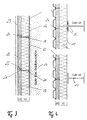
- the substructure has cassettes 15.
- cassettes 15 or Cassette profiles are in the embodiment of Figures 3 and 4 with the interposition of a so-called compriband 16 on one Steel substructure, such as the steel supports 17, attached.
- an Isocell sealing tape 18 is inserted between the cassettes 15, so that the Cassette profiles do not collide directly and are windproof lie together.
- the spaces formed by the cassettes 15 are included relatively soft insulation material 19 filled.
- the webs 20 of the cassettes 15 have angled brackets 21, on which usually one Cladding is attached.
- the Screws 24 first penetrate in the area of the wave valley Cladding 23, then the layer of relatively hard insulation boards and finally the bracket 21 of the cassettes 15 on which the screws are attached.
- FIG. 3 clearly shows that the relatively firm insulation boards 22 matched abutment surfaces 25 with overlaps like a Have tongue and groove connection. This allows using the screw 24 to fix two adjacent plates 22 and certain Compensate for inaccuracies, without the joints between the relatively hard plates 22 a continuous gap is formed.
- the present invention thus allows soft use Insulation material 19 and hard insulation panels 22 on a building envelope to combine the advantages of both insulation materials in an ideal way.
- FIGS. 5 and 6 show the use of those in FIGS. 3 and 4 described type of building shell on reinforced concrete columns and one Wooden substructure. Again, between the cassettes 26 and the reinforced concrete column 27 inserted compression strips 28. The cassettes 26 are attached to an HTU rail 29 fastened in the reinforced concrete column the reinforced concrete column 27 attached. Here too is the relative solid insulation formed from plates 30, the tongue and groove connections bump into each other. The cover 31 is then with screws 32 as in the exemplary embodiment described above on the cassettes 26 attached.
- FIGS. 7 to 11 show a further embodiment of a building envelope, in which 33 cassettes 34 are mounted on a substructure.
- This Cassettes 34 are filled with relatively soft insulation material 35, in which In the present case, a soft mineral fiber insulation board is used.
- On the Crosspieces 36 of the cassettes 34 are rod-shaped insulation elements with screws 37 38 attached, which consist of a relatively hard insulating material. This allows it to put the panel 39 on the relatively hard insulation panels 38 and to connect with the webs 36 via the screws 37.
- In the area between the rod-shaped insulation elements 38, 38 ' is the entire space between the cassette base 40 and the panel 39 with the relatively soft Insulation material 35 filled.
- Figures 8 to 11 show different types of attachment for attachment of cassettes 34 and 34 '.
- Figures 8 and 11 show the attachment of one or two adjacent cassettes on a T-beam 41 by means of screws 42, 42 'and
- Figures 9 and 10 show the attachment of Cassettes 34 and 34 'by means of mounting rails 43 and 43' Reinforced concrete beams 44.
- the sections shown in Figures 8 to 11 through the Building envelopes all lie in the plane of the relatively hard insulation element 38 and thus show the stepped structure made of soft insulation element 35 and harder insulation element 38.
- the exemplary embodiments show that the building envelope for various Substructures 2 can be used.
- the relatively soft insulation material can for example a soft or semi-rigid mineral fiber insulation and in particular be an insulation board. However, it can also be any other insulation materials are used.
- the present exemplary embodiments relate to the insulation of Wall elements.
- the principle according to the invention is also for oblique or horizontal substructures, such as roofs in particular use.
- a horizontal arrangement of the Building shells can also be a bulk material as a relatively soft insulation material be used.
- the relatively firm insulation boards arranged above preferably consist of pressure-resistant mineral fiber insulation.
- polystyrene panels or other insulation panels are also suitable applicable.
Landscapes
- Engineering & Computer Science (AREA)
- Architecture (AREA)
- Civil Engineering (AREA)
- Structural Engineering (AREA)
- Building Environments (AREA)
Applications Claiming Priority (2)
| Application Number | Priority Date | Filing Date | Title |
|---|---|---|---|
| DE19857402 | 1998-12-12 | ||
| DE1998157402 DE19857402A1 (de) | 1998-12-12 | 1998-12-12 | Gebäudehülle mit einer Unterkonstruktion wie einer Wand oder einem Gerüst |
Publications (2)
| Publication Number | Publication Date |
|---|---|
| EP1008696A2 true EP1008696A2 (fr) | 2000-06-14 |
| EP1008696A3 EP1008696A3 (fr) | 2003-01-29 |
Family
ID=7890883
Family Applications (1)
| Application Number | Title | Priority Date | Filing Date |
|---|---|---|---|
| EP99124740A Withdrawn EP1008696A3 (fr) | 1998-12-12 | 1999-12-13 | Habillage de bâtiment avec une structure porteuse comme un mur ou une ossature |
Country Status (2)
| Country | Link |
|---|---|
| EP (1) | EP1008696A3 (fr) |
| DE (1) | DE19857402A1 (fr) |
Family Cites Families (6)
| Publication number | Priority date | Publication date | Assignee | Title |
|---|---|---|---|---|
| CH666310A5 (en) * | 1984-07-18 | 1988-07-15 | Peter Schaer Ag | Facade cladding fixing device - comprises bracket extending through insulation material and accommodating anchoring member for cladding |
| CH683114A5 (de) * | 1991-04-04 | 1994-01-14 | Hans Bigler | Aussenwand, insbesondere für Industrie- und Gewerbebauten, und Verfahren zu ihrer Herstellung. |
| DE4323717A1 (de) * | 1992-07-14 | 1994-01-20 | Franz Hoelzel | Wärmedämmelement für Gebäudewände mit Vorhangfassade |
| EP0829593B1 (fr) * | 1996-09-12 | 1999-08-04 | Sto Verotec GmbH | Revêtement de murs externes suspendu et à ventilation arrière |
| DE19704112C2 (de) * | 1996-12-04 | 2001-10-18 | Peter Kellner | Wärmedämmende Fassadenverkleidung |
| EP0849420A1 (fr) * | 1997-10-10 | 1998-06-24 | Schneider & Co. Leichtbausysteme | Mur rideau à isolation thermique |
-
1998
- 1998-12-12 DE DE1998157402 patent/DE19857402A1/de not_active Withdrawn
-
1999
- 1999-12-13 EP EP99124740A patent/EP1008696A3/fr not_active Withdrawn
Also Published As
| Publication number | Publication date |
|---|---|
| EP1008696A3 (fr) | 2003-01-29 |
| DE19857402A1 (de) | 2000-06-15 |
Similar Documents
| Publication | Publication Date | Title |
|---|---|---|
| DE69000780T2 (de) | Mit fliesen verkleidetes wandsystem. | |
| DE69503182T3 (de) | Dachunterkonstruktion für mit Dacheindeckungsplatten gedeckte Dächer und Verfahren zur Herstellung der Dachunterkonstruktion | |
| DE10147831B4 (de) | Ständerwand | |
| EP0100431A1 (fr) | Revêtement insonorisant et calorifuge pour mur | |
| DE19827790A1 (de) | Gebäudehülle mit einer Unterkonstruktion wie einer Wand oder einem Gerüst | |
| EP1160386B1 (fr) | Façade ventilée et procédé pour sa réalisation | |
| EP1008696A2 (fr) | Habillage de bâtiment avec une structure porteuse comme un mur ou une ossature | |
| DE19807016A1 (de) | Zweischaliges Blechdach mit zwischenliegender Wärmedämmung aus Rollfilzen | |
| DE7342923U (de) | Wärmedämmung für die Anordnung einer hinterlüfteten justierbaren Bauelementenverkleidung | |
| DE19721165A1 (de) | Industriell vorfertigbare Leichtbau-Decken- oder Dachtafeln | |
| DE3622648C2 (fr) | ||
| AT17073U1 (de) | Lastabtragendes Ausgleichselement mit Wärmedämmung | |
| DE2117132A1 (de) | Vorrichtung zur Verbindung von Fassadenelementen untereinander und mit dem Gerippe eines Bauwerks | |
| DE19743846C2 (de) | Sattel- oder Krüppelwalmdach | |
| DE202021103740U1 (de) | Vormontiertes isoliertes Fensterbanksystem | |
| DE102022131325B4 (de) | Anordnung von Schalungselementen | |
| DE10300657A1 (de) | Wandelement | |
| DE102020125702B4 (de) | Belag für den Außenbereich | |
| DE10221692B4 (de) | Wärmedämmverbundsystem und im System verwendbare Dämmplatte | |
| DE60121182T2 (de) | Selbsttragendes baulelement aus holz | |
| EP1286004B1 (fr) | Système composé pour isolation thermique et panneau isolant pour un tel système | |
| EP1445395B1 (fr) | Système de toiture et procédé de couverture d'une toiture | |
| EP0166012B1 (fr) | Fixation pour un revêtement de bâtiment ventilé en arrière | |
| DE3441316A1 (de) | Waermedaemmendes unterdach | |
| DE202024105689U1 (de) | Stab und Bauelement mit solchen Stäben |
Legal Events
| Date | Code | Title | Description |
|---|---|---|---|
| PUAI | Public reference made under article 153(3) epc to a published international application that has entered the european phase |
Free format text: ORIGINAL CODE: 0009012 |
|
| AK | Designated contracting states |
Kind code of ref document: A2 Designated state(s): AT BE CH CY DE DK ES FI FR GB GR IE IT LI LU MC NL PT SE |
|
| AX | Request for extension of the european patent |
Free format text: AL;LT;LV;MK;RO;SI |
|
| RAP1 | Party data changed (applicant data changed or rights of an application transferred) |
Owner name: PROECKL GMBH |
|
| RIN1 | Information on inventor provided before grant (corrected) |
Inventor name: PROECKL, THOMAS, DR. Inventor name: PROECKL, GERT, DIPL.-ING. |
|
| RIC1 | Information provided on ipc code assigned before grant |
Free format text: 7E 04B 1/76 A, 7E 04H 5/10 B, 7E 04F 13/08 B |
|
| PUAL | Search report despatched |
Free format text: ORIGINAL CODE: 0009013 |
|
| AK | Designated contracting states |
Designated state(s): AT BE CH CY DE DK ES FI FR GB GR IE IT LI LU MC NL PT SE |
|
| AX | Request for extension of the european patent |
Extension state: AL LT LV MK RO SI |
|
| 17P | Request for examination filed |
Effective date: 20030128 |
|
| 17Q | First examination report despatched |
Effective date: 20030320 |
|
| AKX | Designation fees paid |
Designated state(s): AT BE CH CY DE DK ES FI FR GB GR IE IT LI LU MC NL PT SE |
|
| STAA | Information on the status of an ep patent application or granted ep patent |
Free format text: STATUS: THE APPLICATION IS DEEMED TO BE WITHDRAWN |
|
| 18D | Application deemed to be withdrawn |
Effective date: 20031031 |