EP1008700A1 - Vorrichtung mit mehreren, schwenkbar gehaltenen Lamellen - Google Patents
Vorrichtung mit mehreren, schwenkbar gehaltenen Lamellen Download PDFInfo
- Publication number
- EP1008700A1 EP1008700A1 EP99811124A EP99811124A EP1008700A1 EP 1008700 A1 EP1008700 A1 EP 1008700A1 EP 99811124 A EP99811124 A EP 99811124A EP 99811124 A EP99811124 A EP 99811124A EP 1008700 A1 EP1008700 A1 EP 1008700A1
- Authority
- EP
- European Patent Office
- Prior art keywords
- slats
- elements
- edge
- sealing
- window
- Prior art date
- Legal status (The legal status is an assumption and is not a legal conclusion. Google has not performed a legal analysis and makes no representation as to the accuracy of the status listed.)
- Granted
Links
- 241000446313 Lamella Species 0.000 title claims description 22
- 238000007789 sealing Methods 0.000 claims abstract description 46
- 239000003566 sealing material Substances 0.000 claims description 3
- 239000011521 glass Substances 0.000 description 48
- 210000002414 leg Anatomy 0.000 description 21
- 125000006850 spacer group Chemical group 0.000 description 9
- 210000000689 upper leg Anatomy 0.000 description 7
- 229920001296 polysiloxane Polymers 0.000 description 4
- 230000007704 transition Effects 0.000 description 4
- 238000010276 construction Methods 0.000 description 3
- 238000009413 insulation Methods 0.000 description 3
- 239000002184 metal Substances 0.000 description 2
- 229920003023 plastic Polymers 0.000 description 2
- 230000004888 barrier function Effects 0.000 description 1
- 238000005516 engineering process Methods 0.000 description 1
- 230000009969 flowable effect Effects 0.000 description 1
- 239000003292 glue Substances 0.000 description 1
- 239000004033 plastic Substances 0.000 description 1
- 230000001681 protective effect Effects 0.000 description 1
- 230000003716 rejuvenation Effects 0.000 description 1
- 238000000926 separation method Methods 0.000 description 1
- 238000009423 ventilation Methods 0.000 description 1
- XLYOFNOQVPJJNP-UHFFFAOYSA-N water Substances O XLYOFNOQVPJJNP-UHFFFAOYSA-N 0.000 description 1
Images



Classifications
-
- E—FIXED CONSTRUCTIONS
- E04—BUILDING
- E04B—GENERAL BUILDING CONSTRUCTIONS; WALLS, e.g. PARTITIONS; ROOFS; FLOORS; CEILINGS; INSULATION OR OTHER PROTECTION OF BUILDINGS
- E04B7/00—Roofs; Roof construction with regard to insulation
- E04B7/16—Roof structures with movable roof parts
- E04B7/163—Roof structures with movable roof parts characterised by a pivoting movement of the movable roof parts
-
- E—FIXED CONSTRUCTIONS
- E04—BUILDING
- E04D—ROOF COVERINGS; SKY-LIGHTS; GUTTERS; ROOF-WORKING TOOLS
- E04D13/00—Special arrangements or devices in connection with roof coverings; Protection against birds; Roof drainage ; Sky-lights
- E04D13/03—Sky-lights; Domes; Ventilating sky-lights
- E04D13/035—Sky-lights; Domes; Ventilating sky-lights characterised by having movable parts
- E04D13/0351—Sky-lights; Domes; Ventilating sky-lights characterised by having movable parts the parts pivoting about a fixed axis
- E04D13/0354—Sky-lights; Domes; Ventilating sky-lights characterised by having movable parts the parts pivoting about a fixed axis the parts being flat
-
- E—FIXED CONSTRUCTIONS
- E06—DOORS, WINDOWS, SHUTTERS, OR ROLLER BLINDS IN GENERAL; LADDERS
- E06B—FIXED OR MOVABLE CLOSURES FOR OPENINGS IN BUILDINGS, VEHICLES, FENCES OR LIKE ENCLOSURES IN GENERAL, e.g. DOORS, WINDOWS, BLINDS, GATES
- E06B7/00—Special arrangements or measures in connection with doors or windows
- E06B7/02—Special arrangements or measures in connection with doors or windows for providing ventilation, e.g. through double windows; Arrangement of ventilation roses
- E06B7/08—Louvre doors, windows or grilles
- E06B7/084—Louvre doors, windows or grilles with rotatable lamellae
- E06B7/086—Louvre doors, windows or grilles with rotatable lamellae interconnected for concurrent movement
-
- E—FIXED CONSTRUCTIONS
- E06—DOORS, WINDOWS, SHUTTERS, OR ROLLER BLINDS IN GENERAL; LADDERS
- E06B—FIXED OR MOVABLE CLOSURES FOR OPENINGS IN BUILDINGS, VEHICLES, FENCES OR LIKE ENCLOSURES IN GENERAL, e.g. DOORS, WINDOWS, BLINDS, GATES
- E06B7/00—Special arrangements or measures in connection with doors or windows
- E06B7/02—Special arrangements or measures in connection with doors or windows for providing ventilation, e.g. through double windows; Arrangement of ventilation roses
- E06B7/08—Louvre doors, windows or grilles
- E06B7/084—Louvre doors, windows or grilles with rotatable lamellae
- E06B7/086—Louvre doors, windows or grilles with rotatable lamellae interconnected for concurrent movement
- E06B7/098—Louvre doors, windows or grilles with rotatable lamellae interconnected for concurrent movement with weather seal
-
- F—MECHANICAL ENGINEERING; LIGHTING; HEATING; WEAPONS; BLASTING
- F24—HEATING; RANGES; VENTILATING
- F24F—AIR-CONDITIONING; AIR-HUMIDIFICATION; VENTILATION; USE OF AIR CURRENTS FOR SCREENING
- F24F13/00—Details common to, or for air-conditioning, air-humidification, ventilation or use of air currents for screening
- F24F13/08—Air-flow control members, e.g. louvres, grilles, flaps or guide plates
- F24F13/10—Air-flow control members, e.g. louvres, grilles, flaps or guide plates movable, e.g. dampers
- F24F13/14—Air-flow control members, e.g. louvres, grilles, flaps or guide plates movable, e.g. dampers built up of tilting members, e.g. louvre
- F24F13/15—Air-flow control members, e.g. louvres, grilles, flaps or guide plates movable, e.g. dampers built up of tilting members, e.g. louvre with parallel simultaneously tiltable lamellae
-
- F—MECHANICAL ENGINEERING; LIGHTING; HEATING; WEAPONS; BLASTING
- F24—HEATING; RANGES; VENTILATING
- F24F—AIR-CONDITIONING; AIR-HUMIDIFICATION; VENTILATION; USE OF AIR CURRENTS FOR SCREENING
- F24F13/00—Details common to, or for air-conditioning, air-humidification, ventilation or use of air currents for screening
- F24F13/08—Air-flow control members, e.g. louvres, grilles, flaps or guide plates
- F24F13/10—Air-flow control members, e.g. louvres, grilles, flaps or guide plates movable, e.g. dampers
- F24F13/14—Air-flow control members, e.g. louvres, grilles, flaps or guide plates movable, e.g. dampers built up of tilting members, e.g. louvre
- F24F13/1406—Air-flow control members, e.g. louvres, grilles, flaps or guide plates movable, e.g. dampers built up of tilting members, e.g. louvre characterised by sealing means
Definitions
- the invention relates to a device with a plurality of swiveling slats, which are arranged overlapping like a scale in the closed state and End elements protruding from the respective lamella at one side end for the purpose of sealing exhibit.
- a device of the type mentioned is e.g. known from EP 0 607 752 A1.
- the object of the invention is to provide a device of the type mentioned in the introduction, which avoids the disadvantages existing in the prior art.
- the solution according to the invention is defined by the features of claim 1.
- the basic idea of the invention is the end element on the inside of the lamella to attach. The outside of the lamella exposed to the weather is therefore one pure glass surface (free of any sealing or protective elements).
- the side edge of the slats is Glass plate can be defined, it is possible to adjoin slat windows laterally to arrange, which when viewed from the outside form a continuous glass surface and which can be opened independently of each other without being in the overlap area a sealing side seal must be dispensed with.
- Another advantage of the construction according to the invention is that the end element is not need only be an angle, but have the shape of any profile can. A U-profile is particularly preferred.
- the end elements are arranged and designed so that they partially meet each other cover laterally.
- the End elements perpendicular to the lamella surface inward projecting leg surfaces, which in the closed state of the slats has a continuous, straight edge form.
- On the frame of the entire lamella arrangement one can then correspondingly Continuous flat surface can be provided, on which the end elements Lay the closed window to allow a continuous seal on the side.
- Said surface can be covered with an elastic sealing element (rubber lip or the like) be equipped to ensure an airtight seal in any case.
- the end elements are preferably made of essentially nestable U-profiles Metal or (e.g. transparent) plastic.
- the more or less perpendicular to the inside projecting leg surfaces are tapered at the rear end (relative to the front), that they can fit into the front end of the subsequent U-profile.
- the taper can be continuous or step-like.
- the extent of the rejuvenation corresponds approximately to twice the wall thickness of a leg surface.
- the leg surfaces can also be at an angle other than 90 ° to the lamella surface stand. Viewed in cross-section, they are e.g. slightly spread so that a stackable U-shaped profile is formed.
- the length of an end element corresponds approximately to the width of a slat.
- the end element is not offset but congruent with the slat appropriate.
- the end element does not protrude in front or back beyond the slat edge.
- the inner side surface is excluded at the front end, to make room for the slat adjoining the front. But it is also possible shorten the width of the slat on the side edge (e.g. by cutting away the Corners) to facilitate the interlocking of the end elements.
- the slats are double glazing made of two connected by a spacer Window plates (made of glass or plastic).
- the outer window plate faces the inner one protrudes from the front and the inner one from the outside a rear one Protrusion on.
- an insulating air space is now on the inner thigh surface the end elements each have an elastic sealing element attached. This is the case arranged that the air space formed between the successive slats (which extends in the longitudinal direction of the lamella, that is to say parallel to the pivot axis) at the end is completed.
- a sealing strip or the like is advantageously provided on the frame and fits into the end elements intervenes so that when the window is closed a kind of labyrinth seal arises. End edge and sealing strips enable a double seal.
- the end element can have a back formed with an offset. Is it glued with the back to the inside of the slat, is due to the offset Gap formed between the lamella surface and the back of the end element, which can be filled with a flowable sealing material (e.g. silicone). On one Gaps of the type mentioned can also be dispensed with, silicone - if at all required - e.g. simply at the front at the transition between the slat outer plate and Cover element can be attached covering.
- a flowable sealing material e.g. silicone
- a louvre window is assumed, such as it is described for example in EP 0 607 752 A1.
- the individual slats 1, 2 can be used with the help of swivel brackets (not shown) (see e.g. DE 35 00 114 C2, DE 42 27 278 C2, EP 0 568 495 B1) can be opened and closed.
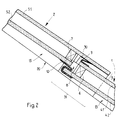
- slats 1, 2 are shown in the closed state.
- the longitudinal direction of the Slats 1, 2 run horizontally to the fall line.
- the swivel bracket is e.g. a quadrilateral joint from wire hangers.
- the pivot axis lies in the area of the rear end of the Slats.
- the slats are operated in parallel.
- the overlaps upper slat 2 scale-like the lower slat 1, with a small at the transition Level 3 is formed. (The terms “top” and "bottom” refer to the roof pitch Are defined.)
- each lamella 1, 2 consists essentially of two glass plates 4.1, 4.2 or 5.1, 5.2, which are tightly connected via a spacer frame 6 or 7.
- the glass plates 4.1, 4.2 or 5.1, 5.2 are rectangular.
- the exterior Glass plate 5.1 protrudes at the lower end of the lamella 2, for example 5 cm above the spacer frame 7 and the inner glass plate 5.2.
- the inner glass plate 4.2 protrudes on the rear or upper end of the slat 1 over the spacer frame 6 and the rear edge of the outer glass plate 4.1 addition.
- the protrusion of the inner glass plate 4.2 is less than that of the outer glass plate 5.1. (Of course, all slats are designed the same. What is said in relation to the slat 1 applies accordingly to the slat 2.)
- an intermediate space 8 is created, which is parallel to the pivot axis of the slats 1, 2 (i.e. perpendicular to Drawing plane of Fig. 2) extends.
- a sealing lip 9 at the rear end of the upper Glass plate 4.1 lies sealingly on the protruding front end of the outer Glass plate 5.1 of the upper lamella 2.
- the gap 8 in the longitudinal direction of the slats 1, 2 i.e. parallel to the pivot axis of the not closer bracket shown
- this sealing lip 10 and Glass plate 5.2 is the wire bracket of the holder, not shown, from the inside to the outside where it grips the front edge of the glass plate 5.2.
- the outer glass plate 4.1 has side regions 11, 12 which protrude laterally beyond the spacer frame 6. According to the invention, this is on the inside (i.e. on the side of the spacer frame 6) each have an essentially U-shaped end element 13, 14 attached.
- the length of the end elements 13, 14 corresponds approximately to the width B of the lamella 1. (The longitudinal direction of the slat is defined by the pivot axis of the bracket. This runs from left to right in Fig. 4)
- a sealing lip 17 engages in the end element, which seals on a roof window frame 16 is attached. Due to level 3, which is between successive Slats 1, 2 is inevitably present, this seal is not when exposed to wind sufficient. It is therefore between the laterally inner (i.e. the spacer frame 6 adjacent) leg surface 18.1 and the roof window frame 16 another Sealing lip 19 is provided.
- the thigh area 18.1 is designed such that during the transition from one slat to the next no step arises.
- the end edge 20, which by the lower Edge of the leg surface 18.1 is defined, lies on the same for all lamellae 1, 2 continuous (i.e. stepless) line or straight line.
- the outer leg surface 18.2 is e.g. in the area of the side edge 33 of the outer Glass plate 4.1. It directs the water into a gutter attached to the skylight frame 16 21. As indicated in FIG. 4, the leg surface 18.2 runs (with rectangular outer glass plate) slightly oblique to the side edge, being at the front The end protrudes slightly beyond this.
- the end element 13 is with its back surface 22 on the inside of the Glued glass plate 4.1.
- the back surface 22 with a slight offset, so that between glass plate 4.1 and a part of the back surface 22 a gap 23 is formed, which with a sealing material (e.g. silicone) can be filled.
- a sealing material e.g. silicone
- 3a-c show a preferred embodiment of the end element 14.
- the end elements 13 and 14 - cf. Fig. 4 - are mirror images of each other, the Closing elements 13 and 15 - cf. Fig. 1 - however identical.
- the final element is formed such that the front end 24 can be nested over the rear end 25 (of the subsequent end element) can be pushed.
- the distance between the leg surfaces 26.1 and 26.2 takes at least around the back to the front Sum of the wall thicknesses of the leg surfaces.
- the change in cross-section of the termination element continuously (i.e. there is no gradation).
- the inner i.e. facing the spacer frame
- Leg surface 26.2 an approximately rectangular recess 27. This fits the rearmost part of the outer glass plate of the following slat.
- a z. B. rectangular protruding into the expansion stage 36 provided.
- a sealing element 34 may be attached, the lower one Edge has a "height" which corresponds to the upper edge of the sealing element 32.
- the sealing element 34 of the rear end element see e.g.
- the back surface 28 has an offset 29 approximately in the middle, as a result of which one half the back surface 28 relative to the other half by, for example, 1-2 mm in height is offset. If the higher half is glued to the glass plate, between a corresponding gap of, for example, the lower half and the glass plate 1-2 mm (see gap 23 in Fig. 1).
- the closure element 13 (of which essentially only the inner leg surface in FIG. 2 18.1 is visible) is attached to the inner or lower side of the glass plate 4.1. So that the front end of the end element 15 seals over the rear End of the end element 13 can be placed so that the inner Leg surfaces of the two end elements 13, 15 on a straight end edge 20 may be, there must be space for the glass plate 4.1 and the seal 9 his.
- FIG. 2 also shows the course of the edge 30 of the recess (see also recess 27 in 4) can be seen relative to the rear end of the glass plate 4.1 or the glass plate 5.2. It creates space for the rear end of the glass plate 4.1 in the end element 15.
- the recess is designed so that said edge 30 z. B. a few millimeters distance to the rear end of the glass plate 4.1. That way inaccuracies the bracket or assembly can be included.
- an elastic at the edge 30 Sealing element may be provided.
- the side seal can also be achieved in that at the rear end of the closure element 13 a sealing element extending to the underside of the outer glass plate 5.1 is appropriate.
- the overlap area 31 between the two end elements 13 and 15 is also shown in Fig. 1. It is typically a few centimeters.
- the difference in height between the rear and front ends 25 and 24 of the end element e.g. 1-2 cm.
- the broadening of the back surface is kept as small as possible in order to avoid that between the outer leg surfaces of the successive end elements a pull-through gap is created.
- With a wall thickness of the order of magnitude 1 mm is the widening by a tolerance greater than 2 mm.
- the back surface e.g. a width of about 3-5 cm.
- the width of the slat (and thus the length of the end element) can e.g. 30 to 50 cm.
- a flat sealing element 32 is attached at the end 25 (cf. FIGS. 3a-c). It can be a rubber hose or the like, which on the thigh surface (e.g. in corresponding grooves) can be hung. It is placed so that when closed Window of the space 8 is closed at the end.
- the sealing element 32 can be extended upwards so far that it extends to the rear side the front end of the next end element is sufficient.
- the sealing element 35 reaches approximately the same height as the rear side at the front end of the end element (see dashed horizontal line).
- FIG. 6a, b show two variants for a terminating element which is not U-shaped but is essentially T-shaped.
- the cross part 38 of the profile 37 is on the Underside of a lamella z. B. glued (similar to the back surface 28 of the in Fig. 3a-c shown final element).
- the cover part 39 which is perpendicular to the cross part 38 protrudes downward, corresponds functionally to the leg surface 18.1. He is at his lower end facing away from the cross part 38, with a socket 40 for a Sealing element 41 equipped.
- the socket 40 is located on the side (i.e. on one of the Main surfaces) of the plate-shaped cover part 39.
- the sealing element 41 is like this formed that it protrudes beyond the lower longitudinal edge of the cover part 39.
- FIG. 6b also has a T-shaped profile 42, one Cross part 43, a cover part 44 and a socket 45 for a sealing element 46.
- the socket on the lower end face or longitudinal edge of the Cover part 44 provided (quasi as a longitudinal groove).
- the sealing element is in from below the longitudinal groove is inserted and projects elastically to the roof window frame 16.
- the cross part 38 or 43 can be advantageous to have a short lateral drip edge on the cross part 38 or 43 to provide. Similar to the end element according to FIGS. 3a-c, the Change the size of the cover part from the back to the front. Furthermore, the cross part be adapted at the front or rear end so that the end elements different slats can work together in a scale-like manner to keep closed Lamellae as good a continuous seal against wind and weather as possible to reach.
- each lamella it is not necessary for each lamella to be coated on both sides with the invention
- End elements is equipped.
- multiple slats which in practice, for example, are no longer than three meters
- slats which in practice, for example, are no longer than three meters
- directly connected at the end using silicone
- only one end element is required per glass pane.
- the end elements are on the inside (i.e. facing the interior) Side) of the outer glass plate.
- the final elements can also be used for louvre windows in which the end elements are attached to the outside of the outer glass plate.
- the cross part 38 or 43 will have to be designed differently (e.g. with a Slot or a socket in which or in which the side edge of the glass plate can be pushed in).
- the cross member and cover Profile instead of T-shaped also L-shaped.
- the end elements each over the rear and / or front Extend the edge of the slat. They can be longer or a little shorter than that Width of the slat. (To ensure that the end elements overlap, have at least over the rear edge of the outer glass plate of the insulating pane protrude.)
- the recess 27 on the inner Thigh surface to be dispensed with.
- the terminating edge 20 is e.g. a particularly flexible sealing strip (in particular a flexible lip or a fine tube) is used, while the sealing lip 17, which represents a first barrier against the external air pressure, quite a certain one May have firmness.
- the sealing lip 19 can also be dispensed with.
- the typically Support surface on the window frame perpendicular to the thigh surface can simply be coated or covered with a rubber or the like.
- the back side need not be tapered in the longitudinal direction.
- the end element does not necessarily have to be U-shaped in cross section.
- further leg surfaces can be formed like a comb next to one another, so that several Longitudinal channels for engaging sealing strips are available.
- the The end edge is also provided on the outer or outermost leg surface his.
- the drip edge can be designed in another way or even omitted.
- An L-shaped profile should also be mentioned as a closing element.
- the end element does not need to be flush with the side edge of the slat, but can clearly protrude beyond it.
- the outer glass plate of the slat can be cut slightly trapezoidal so that the side edge is easy from the back to the front runs outwards.
- the lateral outer leg surface can then be exactly parallel to Side edge of the slat run.
- the invention is also not on insulating glass panes according to the above limited prior art. Even with single glazing can have advantages be achieved compared to the prior art.
- the invention is a significantly improved Side end for scale-like overlapping louvre windows has been created. Good insulation is ensured even under wind loads.
Landscapes
- Engineering & Computer Science (AREA)
- Civil Engineering (AREA)
- Structural Engineering (AREA)
- Architecture (AREA)
- Mechanical Engineering (AREA)
- Electromagnetism (AREA)
- Chemical & Material Sciences (AREA)
- Combustion & Propulsion (AREA)
- Physics & Mathematics (AREA)
- General Engineering & Computer Science (AREA)
- Securing Of Glass Panes Or The Like (AREA)
- Preliminary Treatment Of Fibers (AREA)
- Centrifugal Separators (AREA)
- Control And Other Processes For Unpacking Of Materials (AREA)
- Fastening Of Light Sources Or Lamp Holders (AREA)
- Specific Sealing Or Ventilating Devices For Doors And Windows (AREA)
Abstract
Description
- Fig. 1
- Eine schematische Darstellung des erfindungsgemässen seitlichen Dichtungssystems eines Lamellenfensters;
- Fig. 2
- einen vereinfachten Schnitt des Lamellenfensters parallel zur Fallinie des Dachfensters gemäss Fig. 1;
- Fig. 3a, b, c
- eine perspektivische Darstellung eines Abschlusselementes sowie eine Draufsicht und eine Frontansicht;
- Fig. 4
- eine schematische Darstellung einer Lamelle in der Draufsicht;
- Fig. 5
- eine schematische Darstellung einer Ausführungsvariante zu Fig. 3.
- Fig. 6a, b
- eine schematische Darstellungen von Dichtungsabschlüssen.
Claims (10)
- Vorrichtung mit mehreren, schwenkbar gehaltenen Lamellen (1, 2), welche im geschlossenen Zustand schuppenartig überlappend angeordnet sind und zwecks Abdichtung an einem seitlichen Ende von der jeweiligen Lamelle abstehende Abschlusselemente aufweisen, dadurch gekennzeichnet, dass die Abschlusselemente (13, 14, 15) innenseitig der Lamellen (1, 2) angebracht sind.
- Vorrichtung nach Anspruch 1, dadurch gekennzeichnet, dass die Abschlusselemente (13, 14, 15) derart ausgebildet sind, dass sie im geschlossenen Zustand der Lamellen (1, 2) eine durchgehend gerade Abschlusskante (20) bilden.
- Vorrichtung nach einem der Ansprüche 1 oder 2, dadurch gekennzeichnet, dass die Abschlusselemente (13, 14, 15) im wesentlichen ein verschachtelbares, insbesondere U-förmiges Profil haben.
- Vorrichtung nach einem der Ansprüche 1 bis 3, dadurch gekennzeichnet, dass die Abschlusselemente (13, 14, 15) eine Länge haben, welche im wesentlichen einer Breite der Lamellen (1, 2) entspricht.
- Vorrichtung nach einem der Ansprüche 1 bis 4, dadurch gekennzeichnet, dass an einer innenliegenden Schenkelfläche (26.2) ein Dichtungselement (32) angebracht ist, welches bei geschlossenem Fenster einen zwischen den aufeinanderfolgenden Lamellen (1, 2) gebildeten Zwischenraum (8) seitlich abdichtet.
- Vorrichtung nach Anspruch 5, dadurch gekennzeichnet, dass das Dichtungselement (32) in einem hinteren Bereich des Abschlusselementes (13, 14, 15) angebracht ist und dass die innenliegende Schenkelfläche (26.2) im vorderen Bereich eine Ausnehmung (27) aufweist.
- Vorrichtung nach einem der Ansprüche 1 bis 6, dadurch gekennzeichnet, dass ein Fensterrahmen (16) vorgesehen ist, welcher im Bereich der Abschlusskante (20) ein elastisches Dichtungselement aufweist.
- Vorrichtung nach Anspruch 7, dadurch gekennzeichnet, dass am Fensterrahmen (16) ein elastisches Dichtungselement (17) vorgesehen ist, welches bei geschlossenem Fenster in das Abschlusselement (13) eingreift.
- Vorrichtung nach einem der Ansprüche 1 bis 8, dadurch gekennzeichnet, dass das Abschlusselement (13, 14, 15) eine mit Versatz (29) ausgebildete Rückenfläche (28) aufweist, so dass es mit der Rückenfläche (28) an die Lamelle angeklebt werden kann und dabei einen vorgegebenen Spalt (23) für ein Dichtungsmaterial bildet.
- Vorrichtung nach einem der Ansprüche 1 bis 9, dadurch gekennzeichnet, dass die Lamellen (1, 2) Isolierscheiben aus zwei rahmenlos verbundenen Platten (4.1, 4.2) sind, wobei die Abschlusselemente an seitlich überstehenden Bereichen der äusseren Platten (4.1) angebracht sind.
Applications Claiming Priority (2)
| Application Number | Priority Date | Filing Date | Title |
|---|---|---|---|
| CH243098 | 1998-12-08 | ||
| CH243098 | 1998-12-08 |
Publications (2)
| Publication Number | Publication Date |
|---|---|
| EP1008700A1 true EP1008700A1 (de) | 2000-06-14 |
| EP1008700B1 EP1008700B1 (de) | 2004-02-11 |
Family
ID=4233632
Family Applications (1)
| Application Number | Title | Priority Date | Filing Date |
|---|---|---|---|
| EP99811124A Expired - Lifetime EP1008700B1 (de) | 1998-12-08 | 1999-12-08 | Vorrichtung mit mehreren, schwenkbar gehaltenen Lamellen |
Country Status (5)
| Country | Link |
|---|---|
| EP (1) | EP1008700B1 (de) |
| AT (1) | ATE259453T1 (de) |
| DE (1) | DE59908514D1 (de) |
| ES (1) | ES2215369T3 (de) |
| PT (1) | PT1008700E (de) |
Cited By (2)
| Publication number | Priority date | Publication date | Assignee | Title |
|---|---|---|---|---|
| DE102004027933B3 (de) * | 2004-06-08 | 2006-01-19 | Herbert Lacker | Lamellenfenster |
| DE102005039397B3 (de) * | 2005-08-20 | 2007-03-22 | Herbert Lacker | Lamellenfenster |
Citations (8)
| Publication number | Priority date | Publication date | Assignee | Title |
|---|---|---|---|---|
| DE607752C (de) | 1932-04-22 | 1935-01-07 | Gerhard Ukert | Vorrichtung zum Regeln der Dampfmenge und der Dampftemperatur fuer Schnelldampferzeuger |
| DE3027635A1 (de) * | 1980-01-16 | 1981-07-23 | Hubertus Gerardus J. Milsbeek Peeters | Jalousieventilator, lamelle |
| DE9014003U1 (de) * | 1990-10-08 | 1990-12-13 | Alfred Kunz GmbH & Co, 8000 München | Kontaktaufnahmeprofil, insbesondere für geschirmte Türen mit Türrahmen für abgeschirmte Räume |
| DE3500114C2 (de) | 1985-01-04 | 1992-12-24 | Arthur 8000 Muenchen De Klemt | |
| EP0607752A1 (de) * | 1993-01-18 | 1994-07-27 | Stebler Holding AG | Öffnungsfähiges Dachfenster |
| DE29503974U1 (de) * | 1995-03-08 | 1995-04-27 | E.L. Hirz GmbH & Co KG, 47441 Moers | Dachfenster |
| DE4227278C2 (de) | 1992-08-18 | 1996-07-18 | Stebler Holding Ag | Halteklammer zur verschwenkbaren Halterung einer Glasscheibe, insbesondere aus Mehrscheiben-Isolierglas |
| EP0568495B1 (de) | 1992-05-01 | 1997-06-04 | Stebler Holding AG | Vorrichtung zum Schwenken einer lamellenartigen Platte |
-
1999
- 1999-12-08 ES ES99811124T patent/ES2215369T3/es not_active Expired - Lifetime
- 1999-12-08 AT AT99811124T patent/ATE259453T1/de active
- 1999-12-08 DE DE59908514T patent/DE59908514D1/de not_active Expired - Lifetime
- 1999-12-08 PT PT99811124T patent/PT1008700E/pt unknown
- 1999-12-08 EP EP99811124A patent/EP1008700B1/de not_active Expired - Lifetime
Patent Citations (8)
| Publication number | Priority date | Publication date | Assignee | Title |
|---|---|---|---|---|
| DE607752C (de) | 1932-04-22 | 1935-01-07 | Gerhard Ukert | Vorrichtung zum Regeln der Dampfmenge und der Dampftemperatur fuer Schnelldampferzeuger |
| DE3027635A1 (de) * | 1980-01-16 | 1981-07-23 | Hubertus Gerardus J. Milsbeek Peeters | Jalousieventilator, lamelle |
| DE3500114C2 (de) | 1985-01-04 | 1992-12-24 | Arthur 8000 Muenchen De Klemt | |
| DE9014003U1 (de) * | 1990-10-08 | 1990-12-13 | Alfred Kunz GmbH & Co, 8000 München | Kontaktaufnahmeprofil, insbesondere für geschirmte Türen mit Türrahmen für abgeschirmte Räume |
| EP0568495B1 (de) | 1992-05-01 | 1997-06-04 | Stebler Holding AG | Vorrichtung zum Schwenken einer lamellenartigen Platte |
| DE4227278C2 (de) | 1992-08-18 | 1996-07-18 | Stebler Holding Ag | Halteklammer zur verschwenkbaren Halterung einer Glasscheibe, insbesondere aus Mehrscheiben-Isolierglas |
| EP0607752A1 (de) * | 1993-01-18 | 1994-07-27 | Stebler Holding AG | Öffnungsfähiges Dachfenster |
| DE29503974U1 (de) * | 1995-03-08 | 1995-04-27 | E.L. Hirz GmbH & Co KG, 47441 Moers | Dachfenster |
Cited By (2)
| Publication number | Priority date | Publication date | Assignee | Title |
|---|---|---|---|---|
| DE102004027933B3 (de) * | 2004-06-08 | 2006-01-19 | Herbert Lacker | Lamellenfenster |
| DE102005039397B3 (de) * | 2005-08-20 | 2007-03-22 | Herbert Lacker | Lamellenfenster |
Also Published As
| Publication number | Publication date |
|---|---|
| DE59908514D1 (de) | 2004-03-18 |
| EP1008700B1 (de) | 2004-02-11 |
| ES2215369T3 (es) | 2004-10-01 |
| PT1008700E (pt) | 2004-06-30 |
| ATE259453T1 (de) | 2004-02-15 |
Similar Documents
| Publication | Publication Date | Title |
|---|---|---|
| EP3259428B1 (de) | Dichtungsvorrichtung für fenster- und türelemente | |
| EP0225473B1 (de) | Fenster- oder Türflügel | |
| DE4237606C2 (de) | Container, insbesondere Wohncontainer | |
| EP0658662A1 (de) | Glasfassade mit Fenster | |
| DE202014010902U1 (de) | Isolierelement für Fassaden- oder Lichtdachkonstruktionen | |
| DE4414812C1 (de) | Scharnier zur gelenkigen, aushängbaren Verbindung zweier benachbarter Flügelfelder eines Sektional-Tores | |
| CH648380A5 (de) | Fluegel- und blendrahmen fuer fenster oder verglaste tueren. | |
| DE102015120940A1 (de) | Flachdachfenster in Schwenkflügelbauart | |
| EP3543450B1 (de) | Hebeschiebetür-/schiebetür-profilsystem | |
| EP1008700B1 (de) | Vorrichtung mit mehreren, schwenkbar gehaltenen Lamellen | |
| DE4339467C1 (de) | Dachverglasungssystem | |
| DE19518616C2 (de) | Gewächshaus | |
| DE10011576B4 (de) | Fenster- oder Türrahmen für Container o. dgl. | |
| DE19953675B4 (de) | Kreuzstoßverbindung | |
| CH686633A5 (de) | Oeffenbares Dachfenster. | |
| DE102007033984A1 (de) | Blendrahmenkonstruktion sowie Blendrahmenanordnung | |
| DE4408916A1 (de) | Einbruchhemmendes Fenster | |
| DE3628666A1 (de) | Profilleiste fuer rollaeden | |
| DE9214208U1 (de) | Fenstereinheit | |
| DE3009324A1 (de) | Rahmen zur schraegen verglasung von raeumen | |
| DE4315644C2 (de) | Gebäudefenster | |
| DE2601795C2 (de) | Dichtung am Mittelstoss von Fenstern oder Türen mit horizontal verschiebbaren Flügeln | |
| EP1304444B1 (de) | Tür-oder Fensterelement zum Einsatz in Wandausschnitte | |
| DE4315643C2 (de) | Gebäudefenster | |
| EP0063169A1 (de) | Verbundfenster mit Labyrinthdichtung zwischen Flügelrahmen und Vorsatzrahmen |
Legal Events
| Date | Code | Title | Description |
|---|---|---|---|
| PUAI | Public reference made under article 153(3) epc to a published international application that has entered the european phase |
Free format text: ORIGINAL CODE: 0009012 |
|
| AK | Designated contracting states |
Kind code of ref document: A1 Designated state(s): AT BE CH CY DE DK ES FI FR GB GR IE IT LI LU MC NL PT SE |
|
| AX | Request for extension of the european patent |
Free format text: AL;LT;LV;MK;RO;SI |
|
| 17P | Request for examination filed |
Effective date: 20001207 |
|
| AKX | Designation fees paid |
Free format text: AT BE CH CY DE DK ES FI FR GB GR IE IT LI LU MC NL PT SE |
|
| GRAH | Despatch of communication of intention to grant a patent |
Free format text: ORIGINAL CODE: EPIDOS IGRA |
|
| GRAS | Grant fee paid |
Free format text: ORIGINAL CODE: EPIDOSNIGR3 |
|
| GRAA | (expected) grant |
Free format text: ORIGINAL CODE: 0009210 |
|
| AK | Designated contracting states |
Kind code of ref document: B1 Designated state(s): AT BE CH CY DE DK ES FI FR GB GR IE IT LI LU MC NL PT SE |
|
| PG25 | Lapsed in a contracting state [announced via postgrant information from national office to epo] |
Ref country code: FI Free format text: LAPSE BECAUSE OF FAILURE TO SUBMIT A TRANSLATION OF THE DESCRIPTION OR TO PAY THE FEE WITHIN THE PRESCRIBED TIME-LIMIT Effective date: 20040211 Ref country code: CY Free format text: LAPSE BECAUSE OF FAILURE TO SUBMIT A TRANSLATION OF THE DESCRIPTION OR TO PAY THE FEE WITHIN THE PRESCRIBED TIME-LIMIT Effective date: 20040211 |
|
| REG | Reference to a national code |
Ref country code: GB Ref legal event code: FG4D Free format text: NOT ENGLISH |
|
| REG | Reference to a national code |
Ref country code: CH Ref legal event code: NV Representative=s name: KELLER & PARTNER PATENTANWAELTE AG Ref country code: CH Ref legal event code: EP |
|
| REG | Reference to a national code |
Ref country code: IE Ref legal event code: FG4D Free format text: GERMAN |
|
| REF | Corresponds to: |
Ref document number: 59908514 Country of ref document: DE Date of ref document: 20040318 Kind code of ref document: P |
|
| PG25 | Lapsed in a contracting state [announced via postgrant information from national office to epo] |
Ref country code: SE Free format text: LAPSE BECAUSE OF FAILURE TO SUBMIT A TRANSLATION OF THE DESCRIPTION OR TO PAY THE FEE WITHIN THE PRESCRIBED TIME-LIMIT Effective date: 20040511 Ref country code: GR Free format text: LAPSE BECAUSE OF FAILURE TO SUBMIT A TRANSLATION OF THE DESCRIPTION OR TO PAY THE FEE WITHIN THE PRESCRIBED TIME-LIMIT Effective date: 20040511 Ref country code: DK Free format text: LAPSE BECAUSE OF FAILURE TO SUBMIT A TRANSLATION OF THE DESCRIPTION OR TO PAY THE FEE WITHIN THE PRESCRIBED TIME-LIMIT Effective date: 20040511 |
|
| GBT | Gb: translation of ep patent filed (gb section 77(6)(a)/1977) |
Effective date: 20040513 |
|
| REG | Reference to a national code |
Ref country code: PT Ref legal event code: SC4A Free format text: AVAILABILITY OF NATIONAL TRANSLATION Effective date: 20040511 |
|
| REG | Reference to a national code |
Ref country code: ES Ref legal event code: FG2A Ref document number: 2215369 Country of ref document: ES Kind code of ref document: T3 |
|
| ET | Fr: translation filed | ||
| PLBE | No opposition filed within time limit |
Free format text: ORIGINAL CODE: 0009261 |
|
| STAA | Information on the status of an ep patent application or granted ep patent |
Free format text: STATUS: NO OPPOSITION FILED WITHIN TIME LIMIT |
|
| 26N | No opposition filed |
Effective date: 20041112 |
|
| PG25 | Lapsed in a contracting state [announced via postgrant information from national office to epo] |
Ref country code: IT Free format text: LAPSE BECAUSE OF NON-PAYMENT OF DUE FEES Effective date: 20071208 |
|
| REG | Reference to a national code |
Ref country code: CH Ref legal event code: NV Representative=s name: P&TS SA |
|
| PGRI | Patent reinstated in contracting state [announced from national office to epo] |
Ref country code: IT Effective date: 20110616 |
|
| REG | Reference to a national code |
Ref country code: FR Ref legal event code: PLFP Year of fee payment: 17 |
|
| REG | Reference to a national code |
Ref country code: FR Ref legal event code: PLFP Year of fee payment: 18 |
|
| PGFP | Annual fee paid to national office [announced via postgrant information from national office to epo] |
Ref country code: MC Payment date: 20161214 Year of fee payment: 18 Ref country code: NL Payment date: 20161221 Year of fee payment: 18 Ref country code: LU Payment date: 20161227 Year of fee payment: 18 |
|
| PGFP | Annual fee paid to national office [announced via postgrant information from national office to epo] |
Ref country code: ES Payment date: 20161213 Year of fee payment: 18 Ref country code: PT Payment date: 20161202 Year of fee payment: 18 Ref country code: BE Payment date: 20161221 Year of fee payment: 18 |
|
| REG | Reference to a national code |
Ref country code: FR Ref legal event code: PLFP Year of fee payment: 19 |
|
| PGFP | Annual fee paid to national office [announced via postgrant information from national office to epo] |
Ref country code: FR Payment date: 20171221 Year of fee payment: 19 Ref country code: DE Payment date: 20171211 Year of fee payment: 19 |
|
| PGFP | Annual fee paid to national office [announced via postgrant information from national office to epo] |
Ref country code: IE Payment date: 20171221 Year of fee payment: 19 Ref country code: GB Payment date: 20171221 Year of fee payment: 19 Ref country code: AT Payment date: 20171221 Year of fee payment: 19 |
|
| PGFP | Annual fee paid to national office [announced via postgrant information from national office to epo] |
Ref country code: IT Payment date: 20171221 Year of fee payment: 19 |
|
| PG25 | Lapsed in a contracting state [announced via postgrant information from national office to epo] |
Ref country code: PT Free format text: LAPSE BECAUSE OF NON-PAYMENT OF DUE FEES Effective date: 20180608 |
|
| REG | Reference to a national code |
Ref country code: NL Ref legal event code: MM Effective date: 20180101 |
|
| PG25 | Lapsed in a contracting state [announced via postgrant information from national office to epo] |
Ref country code: NL Free format text: LAPSE BECAUSE OF NON-PAYMENT OF DUE FEES Effective date: 20180101 Ref country code: LU Free format text: LAPSE BECAUSE OF NON-PAYMENT OF DUE FEES Effective date: 20171208 |
|
| REG | Reference to a national code |
Ref country code: BE Ref legal event code: MM Effective date: 20171231 |
|
| PG25 | Lapsed in a contracting state [announced via postgrant information from national office to epo] |
Ref country code: BE Free format text: LAPSE BECAUSE OF NON-PAYMENT OF DUE FEES Effective date: 20171231 |
|
| PGFP | Annual fee paid to national office [announced via postgrant information from national office to epo] |
Ref country code: CH Payment date: 20181218 Year of fee payment: 20 |
|
| PG25 | Lapsed in a contracting state [announced via postgrant information from national office to epo] |
Ref country code: MC Free format text: LAPSE BECAUSE OF NON-PAYMENT OF DUE FEES Effective date: 20180102 |
|
| REG | Reference to a national code |
Ref country code: DE Ref legal event code: R119 Ref document number: 59908514 Country of ref document: DE Ref country code: ES Ref legal event code: FD2A Effective date: 20190702 |
|
| PG25 | Lapsed in a contracting state [announced via postgrant information from national office to epo] |
Ref country code: ES Free format text: LAPSE BECAUSE OF NON-PAYMENT OF DUE FEES Effective date: 20171209 |
|
| REG | Reference to a national code |
Ref country code: AT Ref legal event code: MM01 Ref document number: 259453 Country of ref document: AT Kind code of ref document: T Effective date: 20181208 |
|
| GBPC | Gb: european patent ceased through non-payment of renewal fee |
Effective date: 20181208 |
|
| REG | Reference to a national code |
Ref country code: IE Ref legal event code: MM4A |
|
| PG25 | Lapsed in a contracting state [announced via postgrant information from national office to epo] |
Ref country code: IT Free format text: LAPSE BECAUSE OF NON-PAYMENT OF DUE FEES Effective date: 20181208 Ref country code: IE Free format text: LAPSE BECAUSE OF NON-PAYMENT OF DUE FEES Effective date: 20181208 Ref country code: FR Free format text: LAPSE BECAUSE OF NON-PAYMENT OF DUE FEES Effective date: 20181231 Ref country code: DE Free format text: LAPSE BECAUSE OF NON-PAYMENT OF DUE FEES Effective date: 20190702 |
|
| REG | Reference to a national code |
Ref country code: CH Ref legal event code: PL |
|
| PG25 | Lapsed in a contracting state [announced via postgrant information from national office to epo] |
Ref country code: GB Free format text: LAPSE BECAUSE OF NON-PAYMENT OF DUE FEES Effective date: 20181208 Ref country code: AT Free format text: LAPSE BECAUSE OF NON-PAYMENT OF DUE FEES Effective date: 20181208 |