EP1008752A2 - Kompressorkolben, und Verfahren zu ihrer Beschichtung - Google Patents
Kompressorkolben, und Verfahren zu ihrer Beschichtung Download PDFInfo
- Publication number
- EP1008752A2 EP1008752A2 EP99124469A EP99124469A EP1008752A2 EP 1008752 A2 EP1008752 A2 EP 1008752A2 EP 99124469 A EP99124469 A EP 99124469A EP 99124469 A EP99124469 A EP 99124469A EP 1008752 A2 EP1008752 A2 EP 1008752A2
- Authority
- EP
- European Patent Office
- Prior art keywords
- piston
- coating
- compressor
- recited
- fluororesin
- Prior art date
- Legal status (The legal status is an assumption and is not a legal conclusion. Google has not performed a legal analysis and makes no representation as to the accuracy of the status listed.)
- Withdrawn
Links
Images


Classifications
-
- F—MECHANICAL ENGINEERING; LIGHTING; HEATING; WEAPONS; BLASTING
- F04—POSITIVE - DISPLACEMENT MACHINES FOR LIQUIDS; PUMPS FOR LIQUIDS OR ELASTIC FLUIDS
- F04B—POSITIVE-DISPLACEMENT MACHINES FOR LIQUIDS; PUMPS
- F04B27/00—Multi-cylinder pumps specially adapted for elastic fluids and characterised by number or arrangement of cylinders
- F04B27/08—Multi-cylinder pumps specially adapted for elastic fluids and characterised by number or arrangement of cylinders having cylinders coaxial with, or parallel or inclined to, main shaft axis
- F04B27/0873—Component parts, e.g. sealings; Manufacturing or assembly thereof
- F04B27/0878—Pistons
-
- F—MECHANICAL ENGINEERING; LIGHTING; HEATING; WEAPONS; BLASTING
- F04—POSITIVE - DISPLACEMENT MACHINES FOR LIQUIDS; PUMPS FOR LIQUIDS OR ELASTIC FLUIDS
- F04B—POSITIVE-DISPLACEMENT MACHINES FOR LIQUIDS; PUMPS
- F04B39/00—Component parts, details, or accessories, of pumps or pumping systems specially adapted for elastic fluids, not otherwise provided for in, or of interest apart from, groups F04B25/00 - F04B37/00
- F04B39/0005—Component parts, details, or accessories, of pumps or pumping systems specially adapted for elastic fluids, not otherwise provided for in, or of interest apart from, groups F04B25/00 - F04B37/00 adaptations of pistons
-
- F—MECHANICAL ENGINEERING; LIGHTING; HEATING; WEAPONS; BLASTING
- F05—INDEXING SCHEMES RELATING TO ENGINES OR PUMPS IN VARIOUS SUBCLASSES OF CLASSES F01-F04
- F05C—INDEXING SCHEME RELATING TO MATERIALS, MATERIAL PROPERTIES OR MATERIAL CHARACTERISTICS FOR MACHINES, ENGINES OR PUMPS OTHER THAN NON-POSITIVE-DISPLACEMENT MACHINES OR ENGINES
- F05C2225/00—Synthetic polymers, e.g. plastics; Rubber
- F05C2225/04—PTFE [PolyTetraFluorEthylene]
-
- F—MECHANICAL ENGINEERING; LIGHTING; HEATING; WEAPONS; BLASTING
- F05—INDEXING SCHEMES RELATING TO ENGINES OR PUMPS IN VARIOUS SUBCLASSES OF CLASSES F01-F04
- F05C—INDEXING SCHEME RELATING TO MATERIALS, MATERIAL PROPERTIES OR MATERIAL CHARACTERISTICS FOR MACHINES, ENGINES OR PUMPS OTHER THAN NON-POSITIVE-DISPLACEMENT MACHINES OR ENGINES
- F05C2251/00—Material properties
- F05C2251/14—Self lubricating materials; Solid lubricants
-
- F—MECHANICAL ENGINEERING; LIGHTING; HEATING; WEAPONS; BLASTING
- F05—INDEXING SCHEMES RELATING TO ENGINES OR PUMPS IN VARIOUS SUBCLASSES OF CLASSES F01-F04
- F05C—INDEXING SCHEME RELATING TO MATERIALS, MATERIAL PROPERTIES OR MATERIAL CHARACTERISTICS FOR MACHINES, ENGINES OR PUMPS OTHER THAN NON-POSITIVE-DISPLACEMENT MACHINES OR ENGINES
- F05C2253/00—Other material characteristics; Treatment of material
- F05C2253/12—Coating
Definitions
- the present invention relates to pistons for compressors that are used in vehicle air conditioners and to a method for coating pistons.
- Compressors are employed in air-conditioning systems for vehicles. Piston type compressors are used in such systems. Pistons having no piston rings are known in the art. Such a piston directly contacts the wall of the corresponding cylinder bore and must have good sliding and sealing characteristics and high wear resistance. The surface of a ringless piston is therefore coated.
- the principal components of the coating include fluororesin and binder. The fluororesin permits the piston to reciprocate smoothly in the cylinder bore. The binder firmly adheres the coating layer to the surface of the piston.
- the coating layer is formed by applying a coating material on a piston and curing it thereafter. Then, the coating layer is ground to make the thickness of the coating layer uniform.
- the fluororesin in the coating layer is deposited in a zone proximate to the surface of the coating layer. Much of the fluororesin is thus removed when the surface of the coating layer is ground. The sliding characteristics of the piston may therefore deteriorate, which lowers the compression efficiency of the compressor.
- a piston for reciprocating in a cylinder bore of a compressor includes a head for contacting a wall of the cylinder bore and a coating layer formed on an outer surface of the head.
- the coating layer includes fluororesin and a binder.
- the surface of the coating layer has a relatively high concentration of the fluororesin for reducing friction when the piston reciprocates.
- a method of coating a compressor piston uses a transfer member, a coating material that includes fluororesin and a binder, the coating material being applied to an outer surface of a head of the piston.
- the method includes separating the piston and the transfer member instantaneously when the coating material has been applied to the entire circumference of the head.
- Figs. 1 to 5 illustrate a first embodiment.
- the compressor includes a pair of cylinder blocks 11, 12 and front and rear housings 13, 14.
- the cylinder blocks 11, 12 and the housings 13, 14 are made of aluminum alloy.
- the cylinder blocks 11, 12 are coaxially joined together.
- the front housing 13 is coupled to the front end of the front cylinder block 11 by way of a valve plate 15.
- the rear housing 14 is coupled to the rear end of the rear cylinder block 12 by way of a valve plate 16.
- a drive shaft 18 extends through the center of the cylinder blocks 11, 12 and is supported by a pair of radial bearings 17.
- a swash plate 19 is fixed to the axial center of the drive shaft 18. The swash plate 19 is held between the cylinder blocks 11, 12 with a pair of thrust bearings 20.
- Equally spaced apart cylinder bores 21 are formed in the cylinder blocks 11, 12 about the axis of the drive shaft 18.
- the axes of the bores 21 define a circle, the center of which coincides with the drive shaft axis.
- a piston 22 is reciprocally accommodated in each aligned pair of cylinder bores 21.
- the pistons 22 are made of aluminum alloy.
- the axial center of each piston 22 is coupled to the periphery of the swash plate 19 by pair of shoes 23.
- the swash plate 19 When the drive shaft 18 is rotated, the swash plate 19 is rotated integrally. The rotation of the swash plate 19 is converted into reciprocation of the pistons 22. This draws refrigerant gas from an external refrigerant circuit (not shown) into cylinder bores 21 through suction chambers 24, suction ports 25 and suction valve flaps 26. The drawn gas is compressed and discharged to discharge chambers 29 through discharge ports 27 and discharge valve flaps 28. The gas is then discharged from the discharge chambers 29 to the external refrigerant circuit.
- an external refrigerant circuit not shown
- each piston 22 is substantially cylindrical and has two heads 31.
- One of the heads 31 is located in the associated cylinder bore 21 of the front cylinder block 11 and the other head 31 is located in the associated cylinder bore 21 of the rear cylinder block 12.
- a trunk 34 is located between the heads 31. The diameter of the trunk 34 is smaller than that of the heads 31.
- a recess 32 is formed in the trunk 34. Shoe seats are formed in the recess 32 for receiving the shoes 23.
- a coating layer 35 is formed on the circumferential surface of each head 31.
- the principal components of the coating layer 35 include fluororesin 36 and binder 37.
- the thickness of the coating layer 35 is tens of micrometers.
- the weight ratio of the binder 37 to the fluororesin 36 is preferably between 0.8 and 3.0.
- the coating layer 35 decreases friction between the piston heads 31 and the inner surface of the cylinder bore 21 and improves the durability of the piston 31.
- the coating layer 35 also seals the cylinder bores 21.
- a relatively great amount of the fluororesin 36 is deposited in the vicinity of the surface of the coating layer 35.
- a relatively great amount of binder 37 is located near the surface of the piston 22.
- the coating layer 35 is formed by a roll coating apparatus 51.
- the roll coating apparatus 51 includes a pan 52, a metal roll 53, a comma roll 54, a transfer roll 55, a work holder 56 and a driving mechanism (not shown).
- a coating material C is stored in the pan 52.
- the metal roll 53 is partialy immersed in the coating material C.
- the transfer roll 55 is made of synthetic rubber and contacts the metal roll 53.
- the comma roll 54 is separated from the metal roll 53 by a predetermined distance.
- the work holder 56 supports the piston 22.
- the axes of the rolls 53 to 55 and the axis of the piston 22 are parallel.
- the driving mechanism has a motor to rotate the work holder 56 and the rolls 53 to 55 in the direction of the arrows in Fig. 3.
- the work holder 56 is supported by a solenoid 57 at its axial ends. Exciting the solenoid 57 instantly moves the piston 22 toward the transfer roll 55. De-exciting the solenoi
- the coating material C in the pan 52 adheres to the metal roll 53.
- the viscosity of the coating material C is 40000 to 50000 centipoise (cP).
- the comma roll 54 adjusts the thickness of the coating material C that has adhered to the metal roll 53.
- the coating material is applied to the transfer roll 55.
- the coating material C on the transfer roll 55 is transferred to the heads 31 of the piston 22 as it is pressed against the transfer roll 55.
- the solenoid 57 separates the piston 22 from the transfer roll 55.
- the viscosity of the coating material C is measured with a BH type viscometer using a No. 7 rotor. During the measurement, the rotor is rotated at 10 rpm.
- the coating material C on the piston 22 is dried and cured to form the coating layer 35.
- the fluororesin 36 and the binder 37 are not significantly soluble with each other.
- the fluororesin 36 moves toward the surface, or toward the air, which does not react chemically with the fluororesin 36.
- a relatively large amount of fluororesin 36 is deposited near the surface of the coating layer 35.
- the binder 37 moves toward the piston 22 and adheres to the piston 22.
- the piston 22 is fitted into a compressor after the coating layer 35 is cured.
- the illustrated embodiment has the following advantages.
- a great amount of fluororesin 36 is deposited on the surface of the coating layer 35, which permits the piston 22 to slide smoothly along the cylinder bore 21. This improves not only the efficiency of the compressor but also improves the piston seal and the durability of the compressor.
- a large amount of binder 37 is located in the vicinity of the piston 22, which firmly adheres the coating layer 35 to the piston 22. Accordingly, the durability of the coating layer 35 is improved.
- the coating layer 35 is not ground after being cured. Thus, part of the fluororesin 36 deposited in the vicinity of the coating surface is not removed. Further, omitting the grinding process simplifies the manufacturing procedure.
- the coating layer 35 has a uniform thickness about the entire the piston 22, which allows the grinding process to be omitted. If the piston 22 were slowly separated from the transfer roll 55, the thickness of the coating layer 35 would be uneven. Specifically, when the piston 22 is separated from the transfer roll 55, the coating material C in contact with the transfer roll 55 bulges.
- the weight ratio of the binder 37 to the fluororesin 36 is between 0.8 and 3.0. Therefore, the binder 37 firmly fixes the coating layer 35 to the piston 22 and the fluororesin 36 permits the piston 22 to smoothly slide in the cylinder bore 21.
- the viscosity of the coating material C is between 40000 to 50000 cP. This viscosity range is not only suitable for the transferring but also prevents the coating material C from dripping when applied to the piston 22. Accordingly, the thickness of the coating layer 35 is uniform.
- the coating material C is transferred to the piston 22 by the transfer roll 55, which is parallel to the axis of the piston 22.
- This arrangement accurately forms a layer 35 of uniform thickness. Also, the arrangement permits the piston 22 to be separated from the transfer roll 55 with a simple structure.
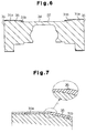
- each piston head 31 includes a cylindrical portion 31a and a tapered portion 31b.
- Each tapered portion 31b is located between the piston trunk 34 and the corresponding cylindrical portion 31a.
- the distance between each tapered portion 31b and the corresponding cylinder bore 21 increases toward the trunk 34.
- the difference between the radius of the cylindrical portion 31a and the minimum radius of the tapered portion 31b is one hundred micrometers at most (The difference is illustrated in an exaggerated manner).
- the coating layer 35 on the cylindrical portion 31a is ground.
- the axial length of the cylindrical portion 31a is substantially equal to that of the tapered portion 31b.
- a large amount of the fluororesin 36 is deposited near the surface of the boundary between the cylindrical portion 31a and the tapered portion 31b and in the tapered portion 31b.
- the fluororesin 36 located in the boundary, or the encircled portion in Fig. 7, permits the piston 22 to smoothly slide in the associated cylinder bore 21.
- Figs. 6 and 7 has the following advantages.
- the fluororesin 36 deposited in the boundary area between the cylindrical portion 31a and the tapered portion 31b permits the piston 22 to smoothly reciprocate in the cylinder bore 21. Therefore, like in the embodiment of Figs. 1 to 5, the compressor operates efficiently.
- the tapered portion 31b permits lubricant to be quickly introduced between the cylindrical portion 31a and the cylinder bore 21. Accordingly, the piston 22 smoothly reciprocates and has a high wear resistance.
- the viscosity of the coating material C may be changed. If the viscosity of the coating material C is between 5000 and 150000 cP, the material C does not drip when applied to the piston 22. More preferably, the viscosity is between 15000 and 50000 cP.
- An agent may be added to the coating material.
- solid lubricant the hardness of which is substantially equal to that of the wall of the cylinder bore 21, may be added to the coating material C.
- the added lubricant resists wear of the coating layer 35 and permits the piston 22 to smoothly reciprocate in the cylinder bore 21.
- the average particle size of the solid lubricant is preferably equal to or smaller than ten micrometers and more preferably between 1 and 5 micrometers.
- the hardness of the solid lubricant is preferably between 2.5 and 4.5 in Moh's hardness and most preferably 4.0 in Moh's hardness. Calcium fluoride has these properties.
- the coating material C may be applied without using the apparatus 51 of Fig. 3.
- the coating material C may be applied to the piston 22 by screen coating method.
- a squeegee presses the coating material against a screen.
- the screen and the squeegee are quickly separated from the piston 22.
- the transfer roll 55 may be moved away from the piston 22 when the application of the material C is completed.
- the present invention may be embodied for manufacturing single headed pistons.
- a compressor piston that smoothly slides in a cylinder bore and a coating method for manufacturing such pistons Coating material (C) is applied to a piston (22) to form a coating layer (35).
- the principal components of the material (C) include fluororesin (36) and a binder (37).
- the coating layer (35) is not ground. Therefore, fluororesin (36), which migrates to the surface of the coating layer (35), is not removed by grinding, which permits the piston (22) to resist friction.
Landscapes
- Engineering & Computer Science (AREA)
- Mechanical Engineering (AREA)
- General Engineering & Computer Science (AREA)
- Manufacturing & Machinery (AREA)
- Compressor (AREA)
- Compressors, Vaccum Pumps And Other Relevant Systems (AREA)
- Pistons, Piston Rings, And Cylinders (AREA)
- Application Of Or Painting With Fluid Materials (AREA)
Applications Claiming Priority (2)
| Application Number | Priority Date | Filing Date | Title |
|---|---|---|---|
| JP10349864A JP2000170657A (ja) | 1998-12-09 | 1998-12-09 | 圧縮機のピストン及びそのピストンのコーティング方法 |
| JP34986498 | 1998-12-09 |
Publications (2)
| Publication Number | Publication Date |
|---|---|
| EP1008752A2 true EP1008752A2 (de) | 2000-06-14 |
| EP1008752A3 EP1008752A3 (de) | 2001-01-17 |
Family
ID=18406643
Family Applications (1)
| Application Number | Title | Priority Date | Filing Date |
|---|---|---|---|
| EP99124469A Withdrawn EP1008752A3 (de) | 1998-12-09 | 1999-12-08 | Kompressorkolben, und Verfahren zu ihrer Beschichtung |
Country Status (6)
| Country | Link |
|---|---|
| US (1) | US6283012B1 (de) |
| EP (1) | EP1008752A3 (de) |
| JP (1) | JP2000170657A (de) |
| KR (1) | KR20000047507A (de) |
| CN (1) | CN1258815A (de) |
| BR (1) | BR9907619A (de) |
Families Citing this family (11)
| Publication number | Priority date | Publication date | Assignee | Title |
|---|---|---|---|---|
| JP2001090654A (ja) * | 1999-09-21 | 2001-04-03 | Toyota Autom Loom Works Ltd | 斜板式圧縮機用ピストンの本体部材製造方法 |
| JP2001153046A (ja) * | 1999-12-01 | 2001-06-05 | Toyota Autom Loom Works Ltd | 圧縮機用ピストン製造方法及びピストン製造装置 |
| JP2002005026A (ja) * | 2000-06-16 | 2002-01-09 | Toyota Industries Corp | ピストン式圧縮機 |
| JP4345250B2 (ja) * | 2000-11-13 | 2009-10-14 | 富士電機システムズ株式会社 | 圧縮機 |
| US6761931B1 (en) * | 2003-01-17 | 2004-07-13 | Delphi Technologies, Inc. | Method for piston coating |
| KR100790274B1 (ko) * | 2003-12-22 | 2007-12-31 | 동부일렉트로닉스 주식회사 | 반도체 웨이퍼 세정설비 |
| DE102004062303A1 (de) * | 2004-12-23 | 2006-07-13 | BSH Bosch und Siemens Hausgeräte GmbH | Linearverdichter |
| US7281465B2 (en) * | 2006-01-09 | 2007-10-16 | Delphi Technologies, Inc. | Compressor piston ball pocket coating |
| KR100915962B1 (ko) | 2007-08-23 | 2009-09-10 | 윤상억 | 압축기용 중공 피스톤 및 그 제조방법 |
| CN104251197B (zh) * | 2013-06-28 | 2017-04-12 | Lg电子株式会社 | 线性压缩机 |
| CN109177189A (zh) * | 2018-07-13 | 2019-01-11 | 中国电子科技集团公司第十六研究所 | 一种小型活塞的耐磨层粘接方法 |
Family Cites Families (21)
| Publication number | Priority date | Publication date | Assignee | Title |
|---|---|---|---|---|
| US4389921A (en) * | 1977-08-12 | 1983-06-28 | Massachusetts Institute Of Technology | Expansible chamber apparatus and its operation |
| JPS5584880A (en) | 1978-12-18 | 1980-06-26 | Toyoda Autom Loom Works Ltd | Compressor |
| JPS5786580A (en) | 1980-11-19 | 1982-05-29 | Toyoda Autom Loom Works Ltd | Piston for swash plate type compressor |
| DE4023135A1 (de) * | 1990-07-20 | 1992-01-23 | Alt Peter | Verfahren und vorrichtung zum beschichten von motorkolben |
| WO1992018560A1 (en) * | 1991-04-22 | 1992-10-29 | Takata Corporation | Surface-coated member |
| US5435873A (en) * | 1991-11-01 | 1995-07-25 | Decc Technology Partnership, A Limited Partnership Of Which The Decc Company, Inc. Is A General Partner | Method and apparatus for sizing a piston |
| US5266142A (en) * | 1991-11-01 | 1993-11-30 | Decc Technology Partnership A Limited Partnership | Coated piston and method and apparatus of coating the same |
| US5363821A (en) * | 1993-07-06 | 1994-11-15 | Ford Motor Company | Thermoset polymer/solid lubricant coating system |
| US5486299A (en) | 1993-11-02 | 1996-01-23 | Dow Corning Asia, Ltd | Wear-resistant lubricant composition |
| US5626907A (en) * | 1994-02-26 | 1997-05-06 | E. I. Dupont De Nemours And Company | Process for coating metal surfaces with a fluororesin using a primer |
| US5469777A (en) * | 1994-07-05 | 1995-11-28 | Ford Motor Company | Piston assembly having abradable coating |
| JP3467328B2 (ja) * | 1994-08-23 | 2003-11-17 | オイレス工業株式会社 | 摺動部材 |
| JP3039762B2 (ja) * | 1995-03-07 | 2000-05-08 | 株式会社豊田自動織機製作所 | 往復動型圧縮機 |
| US5763068A (en) * | 1995-03-27 | 1998-06-09 | Canon Kabushiki Kaisha | Fluororesin-coated member, production method therefor and heat fixing device using the coated member |
| US5655432A (en) * | 1995-12-07 | 1997-08-12 | Ford Motor Company | Swash plate with polyfluoro elastomer coating |
| JP3054589B2 (ja) | 1996-02-29 | 2000-06-19 | 大同メタル工業株式会社 | すべり軸受の軸受構造 |
| DE69728327T2 (de) | 1996-07-08 | 2005-02-10 | Kabushiki Kaisha Toyota Jidoshokki, Kariya | Vorrichtung zur Beschichtung von Kompressorkolben |
| JPH10299654A (ja) | 1997-04-22 | 1998-11-10 | Toyota Autom Loom Works Ltd | ピストン式圧縮機 |
| JP3259215B2 (ja) | 1996-07-08 | 2002-02-25 | 株式会社豊田自動織機 | 圧縮機のピストン及び同ピストンへのコーティング方法 |
| JPH10169557A (ja) | 1996-12-06 | 1998-06-23 | Toyota Autom Loom Works Ltd | 圧縮機 |
| US5996467A (en) * | 1998-08-31 | 1999-12-07 | Ford Motor Company | Polymer-metal coatings for swashplate compressors |
-
1998
- 1998-12-09 JP JP10349864A patent/JP2000170657A/ja active Pending
-
1999
- 1999-10-01 KR KR1019990042270A patent/KR20000047507A/ko not_active Ceased
- 1999-12-07 BR BR9907619-5A patent/BR9907619A/pt unknown
- 1999-12-08 CN CN99124779A patent/CN1258815A/zh active Pending
- 1999-12-08 EP EP99124469A patent/EP1008752A3/de not_active Withdrawn
- 1999-12-08 US US09/457,238 patent/US6283012B1/en not_active Expired - Fee Related
Also Published As
| Publication number | Publication date |
|---|---|
| JP2000170657A (ja) | 2000-06-20 |
| KR20000047507A (ko) | 2000-07-25 |
| CN1258815A (zh) | 2000-07-05 |
| EP1008752A3 (de) | 2001-01-17 |
| US6283012B1 (en) | 2001-09-04 |
| BR9907619A (pt) | 2000-09-19 |
Similar Documents
| Publication | Publication Date | Title |
|---|---|---|
| US6283012B1 (en) | Compressor piston and method for coating piston | |
| US5974946A (en) | Swash plate type compressor using swash plate made of highly wear-resistant material | |
| US5941160A (en) | Pistons for compressors and method and apparatus for coating the pistons | |
| US6217295B1 (en) | Swash plate type compressor | |
| KR100302852B1 (ko) | 압축기용 중공 피스톤 제조방법 | |
| KR20070112851A (ko) | 습동부재용 조성물, 습동부재 및 유체기계 | |
| CN1127619C (zh) | 旋转斜盘式压缩机 | |
| JP3259215B2 (ja) | 圧縮機のピストン及び同ピストンへのコーティング方法 | |
| US20020174764A1 (en) | Swash plate type compressor | |
| JPH10299654A (ja) | ピストン式圧縮機 | |
| EP0995905A2 (de) | Kompressorkolben | |
| EP1136699A2 (de) | Verfahren zum Aufbringen eines Films auf die Taumelscheibe eines Kompressors | |
| US20030106425A1 (en) | Swash plate-type compressor | |
| EP1158163A2 (de) | Kolben für einen Taumelscheibenverdichter | |
| US6487958B2 (en) | Method for forming a film on a constituent part in a compressor | |
| EP0961030A2 (de) | Schmierung von Kolben im Kurbelgehäuse eines Taumelscheibenkompressors | |
| JP2000274349A (ja) | 斜板式圧縮機 | |
| US20250122874A1 (en) | Scroll compressor and method for producing eccentric bush necessary for scroll compressor | |
| JP5518650B2 (ja) | 斜板式圧縮機用シュー | |
| JPH11201038A (ja) | 圧縮機のピストン | |
| KR20210115309A (ko) | 사판식 압축기 | |
| JPH10196527A (ja) | 斜板式圧縮機 | |
| JPH03180404A (ja) | 摺動部材とその製造方法並びにその部材を用いた斜板式圧縮機 | |
| JP2001241378A (ja) | 斜板式圧縮機の斜板における皮膜形成方法 | |
| US20140147317A1 (en) | Compressor with swash plate |
Legal Events
| Date | Code | Title | Description |
|---|---|---|---|
| PUAI | Public reference made under article 153(3) epc to a published international application that has entered the european phase |
Free format text: ORIGINAL CODE: 0009012 |
|
| 17P | Request for examination filed |
Effective date: 19991208 |
|
| AK | Designated contracting states |
Kind code of ref document: A2 Designated state(s): DE FR IT |
|
| AX | Request for extension of the european patent |
Free format text: AL;LT;LV;MK;RO;SI |
|
| RIC1 | Information provided on ipc code assigned before grant |
Free format text: 7F 04B 27/08 A, 7F 04B 39/00 B, 7B 05C 1/02 B |
|
| PUAL | Search report despatched |
Free format text: ORIGINAL CODE: 0009013 |
|
| AK | Designated contracting states |
Kind code of ref document: A3 Designated state(s): AT BE CH CY DE DK ES FI FR GB GR IE IT LI LU MC NL PT SE |
|
| AX | Request for extension of the european patent |
Free format text: AL;LT;LV;MK;RO;SI |
|
| AKX | Designation fees paid |
Free format text: DE FR IT |
|
| STAA | Information on the status of an ep patent application or granted ep patent |
Free format text: STATUS: THE APPLICATION IS DEEMED TO BE WITHDRAWN |
|
| 18D | Application deemed to be withdrawn |
Effective date: 20020702 |