EP1008773A1 - Palier de butée - Google Patents
Palier de butée Download PDFInfo
- Publication number
- EP1008773A1 EP1008773A1 EP19990124459 EP99124459A EP1008773A1 EP 1008773 A1 EP1008773 A1 EP 1008773A1 EP 19990124459 EP19990124459 EP 19990124459 EP 99124459 A EP99124459 A EP 99124459A EP 1008773 A1 EP1008773 A1 EP 1008773A1
- Authority
- EP
- European Patent Office
- Prior art keywords
- shoe
- oil
- thrust bearing
- distribution groove
- recess
- Prior art date
- Legal status (The legal status is an assumption and is not a legal conclusion. Google has not performed a legal analysis and makes no representation as to the accuracy of the status listed.)
- Granted
Links
- 230000000694 effects Effects 0.000 claims description 5
- 230000014759 maintenance of location Effects 0.000 claims 3
- 239000003921 oil Substances 0.000 description 47
- 238000005461 lubrication Methods 0.000 description 2
- 239000000314 lubricant Substances 0.000 description 1
- 239000010687 lubricating oil Substances 0.000 description 1
Images


Classifications
-
- F—MECHANICAL ENGINEERING; LIGHTING; HEATING; WEAPONS; BLASTING
- F16—ENGINEERING ELEMENTS AND UNITS; GENERAL MEASURES FOR PRODUCING AND MAINTAINING EFFECTIVE FUNCTIONING OF MACHINES OR INSTALLATIONS; THERMAL INSULATION IN GENERAL
- F16C—SHAFTS; FLEXIBLE SHAFTS; ELEMENTS OR CRANKSHAFT MECHANISMS; ROTARY BODIES OTHER THAN GEARING ELEMENTS; BEARINGS
- F16C17/00—Sliding-contact bearings for exclusively rotary movement
- F16C17/04—Sliding-contact bearings for exclusively rotary movement for axial load only
- F16C17/06—Sliding-contact bearings for exclusively rotary movement for axial load only with tiltably-supported segments, e.g. Michell bearings
-
- F—MECHANICAL ENGINEERING; LIGHTING; HEATING; WEAPONS; BLASTING
- F16—ENGINEERING ELEMENTS AND UNITS; GENERAL MEASURES FOR PRODUCING AND MAINTAINING EFFECTIVE FUNCTIONING OF MACHINES OR INSTALLATIONS; THERMAL INSULATION IN GENERAL
- F16C—SHAFTS; FLEXIBLE SHAFTS; ELEMENTS OR CRANKSHAFT MECHANISMS; ROTARY BODIES OTHER THAN GEARING ELEMENTS; BEARINGS
- F16C33/00—Parts of bearings; Special methods for making bearings or parts thereof
- F16C33/02—Parts of sliding-contact bearings
- F16C33/04—Brasses; Bushes; Linings
- F16C33/06—Sliding surface mainly made of metal
- F16C33/10—Construction relative to lubrication
- F16C33/1025—Construction relative to lubrication with liquid, e.g. oil, as lubricant
- F16C33/106—Details of distribution or circulation inside the bearings, e.g. details of the bearing surfaces to affect flow or pressure of the liquid
- F16C33/1075—Wedges, e.g. ramps or lobes, for generating pressure
Definitions
- This invention relates to thrust bearings, and more particularly concerns thrust bearings having a leading edge oil distribution groove.
- Kingsbury's LEG thrust bearings which are described in Kingsbury's U.S. Patent No. 4,501,505, which is incorporated herein by reference, overcame the drawbacks of these conventional thrust bearings by providing oil lubricant where it is needed and used, at the working face of the shoe, rather than by flooding the inside of the base ring and the shoes with oil, resulting in a reduction in the amount of lubricating oil needed and a reduction in the frictional power losses, permitting operation at lower film temperatures, and increasing the load carrying capacity of the bearing.
- a thrust bearing having a base ring, and a series of thrust bearing shoes positioned on the base ring, with each shoe having an oil distribution groove formed in its working face near the leading edge of the shoe and a recess formed in the working face of each shoe commencing at the trailing edge of the oil distribution groove and extending rearwardly therefrom to develop hydrodynamic film pressure on the leading edge of each shoe to ensure that each shoe tilts properly at light loads.
- the recess formed in the working face of each shoe is a pocketed region'having a constant depth.
- the recess formed in the working face of each shoe forms a ramp in the working face of each shoe in which the depth of the recess is deepest at the leading edge of the recess and diminishes to no depth at the trailing edge of the recess.
- LEG is a trademark of Kingsbury, Inc., Philadelphia, Pennsylvania.
- the thrust bearing 11 for use with a shaft 13 having a collar 15 mounted on shaft 13 and rotatable therewith.
- the thrust bearing 11 comprises a base ring 17, and a series of shoes 19 positioned around the base ring 17.
- Each shoe 19 has a leading edge 21 connected to a trailing edge 23 by an inner diameter edge 25 and an outer diameter edge 27.
- the direction of rotation of the collar 15 is indicated by an arrow 29.
- Each shoe 19 includes a working face 31, and working face 31 has an outer diameter edge 33 and an inner diameter edge, which in the embodiments of the invention shown in the drawings corresponds to inner diameter edge 25.
- a shoe pivot 35 is mounted on each shoe 19 so as to face away from the working face 31 of the shoe 19, and is provided with a spherical surface to allow the shoe 19 to pivot freely in any direction to conform to the side surfaces of the collar 15.
- Oil distribution groove 37 is formed in the working face 31 of the shoe 19 near the leading edge 21 of the shoe and extends radially for substantially the entire distance between inner diameter edge 25 and outer diameter edge 27 of the shoe 19.
- Oil distribution groove 37 has an inner end 39 and an outer end 41 connected together by a leading edge 43 and a trailing edge 45.
- a bleed groove 47 is provided, which extends radially from the inner end 39 of the oil distribution groove 37 to the inner diameter edge 25 of the shoe 19 for supplying oil to the inner diameter edge area of the shoe 19 downstream of the bleed groove 47, which downstream inner diameter area would otherwise be starved of oil by the centrifugal inertial effects of rotating the collar 15.
- trailing edge 45 of oil distribution groove 37 is chamfered so as to provided a chamfered edge for more easily allowing oil to flow from the oil distribution groove 37 to cover the shoe working face 31 with oil during rotation of shaft 13 and collar 15.
- Retaining means such as retaining pins 79 which extend radially from the shoe 19 into an annular groove 81 in the base ring 17, are provided to assist in retaining the shoes 19 on the base ring 17. Screws also may be used to retain the shoes 19 on the base ring 17.
- upper leveling plates 83 and lower leveling plates 85 which are placed alternately around the base ring 17 in an annular groove 87.
- Lower leveling plates 85 are positioned by axially directed lower leveling plate retainer dowels 89, and upper leveling plates 83 are positioned by upper leveling plate retainer set screws 91 which are radially directed.
- Shoe pivots 35 bear on the upper leveling plates 83, and the action of the alternately placed leveling plates 83, 85 serves to distribute the load evenly among the shoes 19.
- a recess 93 is formed in the working face 31 of each shoe 19 to develop hydrodynamic film pressure on the leading edge 21 of each shoe 19 to ensure that during operation at light loads the shoe 19 tilts properly, that is, with the gap between the shoe 19 at its leading edge 21 and the collar 15 being larger than the gap between the shoe 19 at its trailing edge 23 and the collar 15.
- Recess 93 has an inner end 95 and an outer end 97 connected together by a leading edge 99 and a trailing edge 101.
- the leading edge 99 of recess 93 commences at the trailing edge 45 of the oil distribution groove 37.
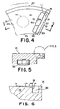
- Figs. 4-6 show a first embodiment of the invention in which the recess 93 forms a ramp 103 in the working face 31 of the shoe 19.
- the depth of the recess 93 is deepest at the leading edge 99 of the recess 93 and diminishes to no depth at the trailing edge 101 of the recess 93.
- the depth of the recess 93 at the leading edge 99 of the recess 93 is 0.0020 inches to 0.0200 inches.
- the width of the recess 93 that is, the distance from the leading edge 99 of the recess 93 to the trailing edge 101 of the recess 93, is measured at the mean diameter of the shoe 19 and locates the trailing edge 101 of the recess 93.
- the mean diameter of the shoe 19 is defined as (o.d. + i.d.)/2, with o.d. being the outer diameter of the thrust bearing measured between the outer edges 33 of working faces 31 of two shoes 19 that are opposite to each other and i. d. being the inner diameter of the thrust bearing measured between the inner edges 25 of the working faces 31 of two shoes 19 that are opposite to each other.
- the width of the recess 93 in degrees is 10% to 25% of the active shoe angle ⁇ , the active shoe angle ⁇ being the interior angle formed by the intersection of (a) a line 102 extending from the trailing edge 101 of the recess 93, at the mean diameter of the shoe 19, to the center 103 of the bearing and (b) a line 104 extending from the trailing edge of the working face 31, which in the embodiments of the invention shown in the drawings corresponds to trailing edge 23 of the shoe 19, at the mean diameter of the shoe 19, to a center 103 of the bearing. (See Fig.3.)
- the trailing edge 101 in this embodiment of the invention, is parallel to the leading edge 21 of the shoe 19.
- the length of the recess 93 that is, the distance from the inner end 95 of recess 93 to the outer end 97 of recess 93, is 75% to 100% of the length of the working face 31 of the shoe 19 (the distance between the inner diameter edge of the working face 31, which in the embodiments of the invention shown in the drawings corresponds to inner diameter edge 25 of the shoe 19, and the outer diameter edge 33 of working face 31 of the shoe 19) and the length of the working face 31 of the shoe 19 is defined as (o.d.-i.d.)/2, with the o.d. being the outer diameter of the thrust bearing measured between the outer edges 33 of working faces 31 of two shoes 19 that are opposite to each other and i.d. being the inner diameter of the thrust bearing measured between the inner edges 25 of working faces 31 of two shoes 19 that are opposite to each other.
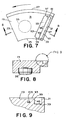
- recess 93 is a pocketed region. That is, the recess 93 forms a plateau 105 in the working face 31 of the shoe 19 that is sunken below the level of the working face 31 surrounding recess 93.
- the depth of the pocketed region is preferably 0.0020 inches to 0.0200 inches and is of constant depth.
- the width of the pocket region that is, the distance from the leading edge 99 of the recess 93 to the trailing edge 101 of the recess 93, is measured at the mean diameter of the shoe.
- the width of the recess 93 in degrees is 10% to 25% of the active shoe angle.
- the trailing edge 101 of recess 93 in these embodiments of the invention is either parallel to the shoe leading edge 21 ( as with the second embodiment of the invention as shown in Figs. 7-9), radial from the bearing center ( as with the third embodiment of the invention as shown in Figs. 10-12), or somewhere in between these two.
- the length of the pocketed region is 75% to 90% of the length of the working face 31 of the shoe 19 (the distance between the inner diameter edge of the working face 31, which in the embodiments of the invention shown in the drawings corresponds to the inner diameter edge 25 of the shoe 19, and the outer diameter edge 33 of working face 31 of the shoe 19) and the length of the working face 31 of the shoe 19 is defined as (o.d.-i.d.)/2, with o.d. being the outer diameter of the thrust bearing measured between the outer edges 33 of working faces 31 of two shoes 19 that are opposite to each other and i.d. being the inner diameter of the thrust bearing measured between the outer edges 25 of the working faces 31 of two shoes 19 that are opposite to each other.
- Fig. 1 illustrates schematically the proper tilt of the shoe 19 during operation.
- the thrust bearings 11 of the invention do not suffer from this condition since the recess 93 formed in the working face 31 of the shoe 19 causes hydrodynamic film pressure to develop on the leading edge 21 of each shoe 19, and this hydrodynamic film pressure causes the shoes 19 to tilt properly, that is, with the gap between the shoe 19 at its leading edge 21 and the collar 15 being larger than the gap between the shoe 19 at its trailing edge 23 and the collar 15, when operating at low thrust loads.
- Recess 93 creates hydrodynamic film pressure on the leading edge 21 of the shoe 19, which creates a moment opposite to the viscous drag moment.
- the dimensions of recess 93 can be varied at the design stage for different applications.
- line 107a indicates the oil supply pressure versus load for a standard 10 1/2 inch LEG thrust bearing at 12.0 KRPM
- line 109a indicates the oil supply pressure versus load for a 10 1/2 inch LEG thrust bearing constructed in accordance with the invention at 12.0 KRPM
- line 107b indicates the oil supply pressure versus load for a standard 10 1/2 inch LEG thrust bearing at 10.0 KRPM
- line 109b indicates the oil supply pressure versus load for a 10 1/2 inch LEG thrust bearing constructed in accordance with the invention at 10.0 KRPM.
- line 107c indicates the oil supply pressure versus load for a standard 10 1/2 inch LEG thrust bearing at 8.0 KRPM
- line 109c indicates the oil supply pressure versus load for a 10 1/2 inch LEG thrust bearing constructed in accordance with the invention at 8.0 KRPM.
- KRPM is an abbreviation for "kilo rotations per minute”. Accordingly, 12.0 KRPM equals 12,000 rotations per minute, 10.0 KRPM equals 10,000 rotations per minute, and 8.0 KRPM equals 8,000 rotations per minute.
- the oil supply pressure at 12.0 KRPM the oil supply pressure ranges between about 30.0 psig and about 52.0 psig when the load is between about 10 psi and 100 psi.
- the oil supply pressure of an LEG thrust bearing constructed in accordance with the invention ranges from about 8.0 psig to about 16.0 psig when the load is between 10.0 psi and 100.0 psi.
- the oil supply pressure at 10.0 KRPM ranges between about 22.0 psig and about 28.0 psig when the load is between about 10 psi and 50 psi.
- the oil supply pressure of an LEG thrust bearing constructed in accordance with the invention ranges from about 4.0 psig to about 6.0 psig when the load is between 10.0 psi and 50.0 psi.
- the oil supply pressure at 8.0 KRPM is about 13.0 psig at a load of about 10 psi.
- the oil supply pressure of an LEG thrust bearing constructed in accordance with the invention is about about 3.0 psig at a load of about 10 psi.
- line 111a, 111b, and 111c indicate the oil film temperature verses load at 12.0 KRPM, 10.0 KRPM, and 8.0 KRPM, respectively, for standard LEG thrust bearings
- lines 113a, 113b, 113c show oil film temperature verses load at 12.0 KRPM, 10.0 KRPM, and 8.0 KRPM, respectively, for LEG thrust bearings constructed in accordance with the invention.
- a marked oil film temperature reduction occurs with the LEG thrust bearings constructed in accordance with the invention in the range of light loads (less than 25 psi) .
- the inventive thrust bearing provides proper shoe tilt so that the gap between the shoe 19 at its leading edge 21 and the collar 15 is greater than the gap between the shoe 19 at its trailing edge 23 and the collar 15, in all conditions of operation.
- normal tilting occurs throughout the design speed range for the thrust bearing during all conditions of operations so that the bearing operates at both light loads (with proper tilt being provided from the hydrodynamic film pressure created by recess 93) and high loads (with proper tilt resulting from the oil film pressures encountered at higher loads).
Landscapes
- Engineering & Computer Science (AREA)
- General Engineering & Computer Science (AREA)
- Mechanical Engineering (AREA)
- Chemical & Material Sciences (AREA)
- Oil, Petroleum & Natural Gas (AREA)
- Sliding-Contact Bearings (AREA)
Applications Claiming Priority (2)
| Application Number | Priority Date | Filing Date | Title |
|---|---|---|---|
| US209403 | 1998-12-10 | ||
| US09/209,403 US6089754A (en) | 1998-12-10 | 1998-12-10 | Thrust bearing |
Publications (2)
| Publication Number | Publication Date |
|---|---|
| EP1008773A1 true EP1008773A1 (fr) | 2000-06-14 |
| EP1008773B1 EP1008773B1 (fr) | 2005-07-06 |
Family
ID=22778623
Family Applications (1)
| Application Number | Title | Priority Date | Filing Date |
|---|---|---|---|
| EP19990124459 Expired - Lifetime EP1008773B1 (fr) | 1998-12-10 | 1999-12-08 | Palier de butée |
Country Status (5)
| Country | Link |
|---|---|
| US (1) | US6089754A (fr) |
| EP (1) | EP1008773B1 (fr) |
| JP (1) | JP2000186712A (fr) |
| CN (1) | CN1147667C (fr) |
| DE (1) | DE69926046T2 (fr) |
Cited By (3)
| Publication number | Priority date | Publication date | Assignee | Title |
|---|---|---|---|---|
| US6976788B2 (en) | 2001-03-27 | 2005-12-20 | Nok Corporation | Thrust bearing |
| US8113798B2 (en) | 2006-10-20 | 2012-02-14 | Atlas Copco Energas Gmbh | Turbomachine with tilt-segment bearing and force measurement arrangemment |
| EP2816226A1 (fr) * | 2013-06-20 | 2014-12-24 | Siemens Aktiengesellschaft | Éolienne à palier lisse |
Families Citing this family (27)
| Publication number | Priority date | Publication date | Assignee | Title |
|---|---|---|---|---|
| US6499883B2 (en) | 1997-03-31 | 2002-12-31 | Whm Holding Corporation | Tilting pad for bearings |
| US6739756B2 (en) | 2001-03-12 | 2004-05-25 | Whm Holding Corporation | Combination thrust bearing and journal bearing, and method for distributing fluid to same |
| US6592490B2 (en) | 2001-05-02 | 2003-07-15 | Baker Hughes Incorporated | Well pump gear box hydrodynamic washer |
| US20020181811A1 (en) * | 2001-06-05 | 2002-12-05 | Aguilar Scott Grover | Diverted flow thrust bearing |
| US7063465B1 (en) * | 2003-03-21 | 2006-06-20 | Kingsbury, Inc. | Thrust bearing |
| US7237957B2 (en) | 2005-02-28 | 2007-07-03 | Kingsbury, Inc. | Journal bearing having self-retaining shoes and method of using the same to support a rotating shaft |
| US7758247B2 (en) * | 2005-02-28 | 2010-07-20 | Kingsbury, Inc. | Journal bearing having surface-contact retained shoes |
| US8182248B2 (en) * | 2007-11-29 | 2012-05-22 | Hamilton Sundstrand Corporation | Vane pump with tilting pad radial bearings |
| CN100591932C (zh) * | 2008-11-14 | 2010-02-24 | 南京高精齿轮集团有限公司 | 推力轴承 |
| DK2376797T3 (en) * | 2008-12-15 | 2016-08-22 | Jochen Corts | Segmented composite bearings and wind generator that uses hydraulic pump / motor combination |
| IT1395717B1 (it) | 2009-09-22 | 2012-10-19 | Nuovo Pignone Spa | Cuscinetto, meccanismo di distribuzione olio e metodo. |
| IT1395716B1 (it) | 2009-09-22 | 2012-10-19 | Nuovo Pignone Spa | Cuscinetto, meccanismo di fissaggio e metodo per fissare almeno un pattino. |
| CN101968078A (zh) * | 2010-09-29 | 2011-02-09 | 李耀强 | 带回油槽的轴瓦 |
| WO2013046404A1 (fr) * | 2011-09-29 | 2013-04-04 | 株式会社日立製作所 | Palier à patins oscillants du type à lubrification directe |
| JP6222952B2 (ja) | 2013-03-19 | 2017-11-01 | 三菱日立パワーシステムズ株式会社 | 回転軸支持構造 |
| CN105324139B (zh) * | 2013-05-23 | 2018-01-26 | 纯净之心有限公司 | 离心泵装置的叶轮 |
| JP2015007463A (ja) * | 2013-06-26 | 2015-01-15 | 三菱日立パワーシステムズ株式会社 | ティルティングパッド軸受 |
| CN103671546B (zh) * | 2013-12-09 | 2016-04-20 | 浙江大学 | 带有阻尼结构的推力滑动轴承 |
| JP6522880B2 (ja) * | 2014-03-14 | 2019-05-29 | 三菱日立パワーシステムズ株式会社 | 軸受装置、回転機械 |
| DE102014213330A1 (de) * | 2014-07-09 | 2016-01-14 | Bosch Mahle Turbo Systems Gmbh & Co. Kg | Ladeeinrichtung |
| DE102014213466A1 (de) * | 2014-07-10 | 2016-01-14 | Bosch Mahle Turbo Systems Gmbh & Co. Kg | Axiallager oder kombiniertes Axial-/Radiallager |
| DE102014222514A1 (de) | 2014-07-10 | 2016-01-14 | Bosch Mahle Turbo Systems Gmbh & Co. Kg | Axiallager |
| CN104658403B (zh) * | 2015-03-09 | 2017-09-19 | 东北大学 | 推力滑动轴承润滑特性教学演示装置 |
| US9874247B2 (en) | 2016-05-09 | 2018-01-23 | Elliott Company | Internal cooling bearing pads |
| CN111022312A (zh) * | 2019-12-18 | 2020-04-17 | 沈阳鼓风机集团核电泵业有限公司 | 一种反应堆冷却剂泵用轴向推力监测装置 |
| DE102020133940B4 (de) | 2020-12-17 | 2026-02-19 | Renk Gmbh | Gleitlager mit Gleitsegmenten |
| CN114738375A (zh) * | 2022-04-15 | 2022-07-12 | 陕西科技大学 | 一种具有多重冷却循环功能的重载推力轴承 |
Citations (7)
| Publication number | Priority date | Publication date | Assignee | Title |
|---|---|---|---|---|
| GB829482A (en) * | 1956-01-16 | 1960-03-02 | Napier & Son Ltd | Rotary thrust bearings or fluid seals |
| CH345205A (de) * | 1955-06-27 | 1960-03-15 | Licentia Gmbh | Drucklager für Turbomaschinen |
| DE2433624A1 (de) * | 1973-09-07 | 1975-03-13 | Judson S Swearingen | Verfahren zum messen und steuern des axialdruckes bei rotationsmaschinen und zugehoerige drucklageranordnung |
| US4348065A (en) * | 1979-07-13 | 1982-09-07 | Hitachi, Ltd. | Thrust bearing |
| US4501505A (en) * | 1984-06-06 | 1985-02-26 | Chambers William S | Thrust bearing |
| EP0259991A2 (fr) * | 1986-09-08 | 1988-03-16 | Delaware Capital Formation Inc. | Palier axial à patins oscillants avec localisation optimale de l'axe d'oscillation |
| DE3924065A1 (de) * | 1988-07-29 | 1990-02-01 | Gen Electric | Schublager-schmiereinrichtung |
Family Cites Families (1)
| Publication number | Priority date | Publication date | Assignee | Title |
|---|---|---|---|---|
| US5007745A (en) * | 1989-09-26 | 1991-04-16 | Delaware Capital Formation, Inc. | Low flow tilting pad thrust bearing |
-
1998
- 1998-12-10 US US09/209,403 patent/US6089754A/en not_active Expired - Lifetime
-
1999
- 1999-12-08 EP EP19990124459 patent/EP1008773B1/fr not_active Expired - Lifetime
- 1999-12-08 DE DE1999626046 patent/DE69926046T2/de not_active Expired - Lifetime
- 1999-12-09 JP JP35030399A patent/JP2000186712A/ja active Pending
- 1999-12-10 CN CNB991259963A patent/CN1147667C/zh not_active Expired - Fee Related
Patent Citations (7)
| Publication number | Priority date | Publication date | Assignee | Title |
|---|---|---|---|---|
| CH345205A (de) * | 1955-06-27 | 1960-03-15 | Licentia Gmbh | Drucklager für Turbomaschinen |
| GB829482A (en) * | 1956-01-16 | 1960-03-02 | Napier & Son Ltd | Rotary thrust bearings or fluid seals |
| DE2433624A1 (de) * | 1973-09-07 | 1975-03-13 | Judson S Swearingen | Verfahren zum messen und steuern des axialdruckes bei rotationsmaschinen und zugehoerige drucklageranordnung |
| US4348065A (en) * | 1979-07-13 | 1982-09-07 | Hitachi, Ltd. | Thrust bearing |
| US4501505A (en) * | 1984-06-06 | 1985-02-26 | Chambers William S | Thrust bearing |
| EP0259991A2 (fr) * | 1986-09-08 | 1988-03-16 | Delaware Capital Formation Inc. | Palier axial à patins oscillants avec localisation optimale de l'axe d'oscillation |
| DE3924065A1 (de) * | 1988-07-29 | 1990-02-01 | Gen Electric | Schublager-schmiereinrichtung |
Cited By (4)
| Publication number | Priority date | Publication date | Assignee | Title |
|---|---|---|---|---|
| US6976788B2 (en) | 2001-03-27 | 2005-12-20 | Nok Corporation | Thrust bearing |
| US8113798B2 (en) | 2006-10-20 | 2012-02-14 | Atlas Copco Energas Gmbh | Turbomachine with tilt-segment bearing and force measurement arrangemment |
| EP2816226A1 (fr) * | 2013-06-20 | 2014-12-24 | Siemens Aktiengesellschaft | Éolienne à palier lisse |
| DE102013211710C5 (de) * | 2013-06-20 | 2016-11-10 | Siemens Aktiengesellschaft | Windkraftanlage mit einem Gleitlager |
Also Published As
| Publication number | Publication date |
|---|---|
| DE69926046T2 (de) | 2006-04-27 |
| US6089754A (en) | 2000-07-18 |
| CN1147667C (zh) | 2004-04-28 |
| EP1008773B1 (fr) | 2005-07-06 |
| CN1256370A (zh) | 2000-06-14 |
| JP2000186712A (ja) | 2000-07-04 |
| DE69926046D1 (de) | 2005-08-11 |
Similar Documents
| Publication | Publication Date | Title |
|---|---|---|
| US6089754A (en) | Thrust bearing | |
| EP0163815B1 (fr) | Palier de butée | |
| US8646979B2 (en) | Hybrid hydro (air) static multi-recess journal bearing | |
| US4425011A (en) | Polymer cage for a high speed tapered roller bearing | |
| US4597676A (en) | Hybrid bearing | |
| US9410572B2 (en) | Five-axial groove cylindrical journal bearing with pressure dams for bi-directional rotation | |
| US9500231B2 (en) | Fractured-outer-race full-complement ball-bearing system incorporated in a turbocharger assembly | |
| EP0009834B1 (fr) | Palier pour vitesses de rotation élevées | |
| JPS58121318A (ja) | オイルフイルムベアリング | |
| JPH03149411A (ja) | 傾斜パッドスラストベアリング | |
| US4490054A (en) | Machine tool bearing system | |
| EP0949428A1 (fr) | Palier de butée dynamique du type fermé avec trou traversant | |
| US3782795A (en) | Tapered roller bearing | |
| CA2484388C (fr) | Haveuse a disque oscillant a paliers de regulation de vitesse | |
| US5399026A (en) | Bearing with lubricating ring for providing supplemental lubrication | |
| US3841720A (en) | Thrust bearing assembly | |
| US5447376A (en) | Package bearing system | |
| RU2578938C2 (ru) | Способ выравнивания осевых нагрузок по несущей поверхности упорных подшипников и упорный подшипник для его осуществления (варианты) | |
| EP0329193A1 (fr) | Construction de palier notamment palier axial | |
| JPS62101916A (ja) | 改良した軸受組立体およびスラスト軸受 | |
| JPH0642099Y2 (ja) | 円錐ころ軸受 | |
| JP3301670B2 (ja) | スラスト軸受 | |
| JPH11336753A (ja) | 自動調心ころ軸受 | |
| Gardner | Tilting pad thrust bearing tests-Influence of oil flow rate on power loss and temperatures | |
| RU2138705C1 (ru) | Комбинированная опора |
Legal Events
| Date | Code | Title | Description |
|---|---|---|---|
| PUAI | Public reference made under article 153(3) epc to a published international application that has entered the european phase |
Free format text: ORIGINAL CODE: 0009012 |
|
| AK | Designated contracting states |
Kind code of ref document: A1 Designated state(s): DE FR GB IT |
|
| AX | Request for extension of the european patent |
Free format text: AL;LT;LV;MK;RO;SI |
|
| 17P | Request for examination filed |
Effective date: 20001212 |
|
| AKX | Designation fees paid |
Free format text: DE FR GB IT |
|
| 17Q | First examination report despatched |
Effective date: 20040212 |
|
| GRAP | Despatch of communication of intention to grant a patent |
Free format text: ORIGINAL CODE: EPIDOSNIGR1 |
|
| GRAS | Grant fee paid |
Free format text: ORIGINAL CODE: EPIDOSNIGR3 |
|
| GRAA | (expected) grant |
Free format text: ORIGINAL CODE: 0009210 |
|
| AK | Designated contracting states |
Kind code of ref document: B1 Designated state(s): DE FR GB IT |
|
| PG25 | Lapsed in a contracting state [announced via postgrant information from national office to epo] |
Ref country code: IT Free format text: LAPSE BECAUSE OF FAILURE TO SUBMIT A TRANSLATION OF THE DESCRIPTION OR TO PAY THE FEE WITHIN THE PRESCRIBED TIME-LIMIT;WARNING: LAPSES OF ITALIAN PATENTS WITH EFFECTIVE DATE BEFORE 2007 MAY HAVE OCCURRED AT ANY TIME BEFORE 2007. THE CORRECT EFFECTIVE DATE MAY BE DIFFERENT FROM THE ONE RECORDED. Effective date: 20050706 |
|
| REG | Reference to a national code |
Ref country code: GB Ref legal event code: FG4D |
|
| REF | Corresponds to: |
Ref document number: 69926046 Country of ref document: DE Date of ref document: 20050811 Kind code of ref document: P |
|
| PLBE | No opposition filed within time limit |
Free format text: ORIGINAL CODE: 0009261 |
|
| STAA | Information on the status of an ep patent application or granted ep patent |
Free format text: STATUS: NO OPPOSITION FILED WITHIN TIME LIMIT |
|
| 26N | No opposition filed |
Effective date: 20060407 |
|
| EN | Fr: translation not filed | ||
| PG25 | Lapsed in a contracting state [announced via postgrant information from national office to epo] |
Ref country code: FR Free format text: LAPSE BECAUSE OF FAILURE TO SUBMIT A TRANSLATION OF THE DESCRIPTION OR TO PAY THE FEE WITHIN THE PRESCRIBED TIME-LIMIT Effective date: 20060901 |
|
| PG25 | Lapsed in a contracting state [announced via postgrant information from national office to epo] |
Ref country code: FR Free format text: LAPSE BECAUSE OF FAILURE TO SUBMIT A TRANSLATION OF THE DESCRIPTION OR TO PAY THE FEE WITHIN THE PRESCRIBED TIME-LIMIT Effective date: 20050706 |
|
| PGFP | Annual fee paid to national office [announced via postgrant information from national office to epo] |
Ref country code: GB Payment date: 20180119 Year of fee payment: 19 Ref country code: DE Payment date: 20180122 Year of fee payment: 19 |
|
| REG | Reference to a national code |
Ref country code: DE Ref legal event code: R119 Ref document number: 69926046 Country of ref document: DE |
|
| GBPC | Gb: european patent ceased through non-payment of renewal fee |
Effective date: 20181208 |
|
| PG25 | Lapsed in a contracting state [announced via postgrant information from national office to epo] |
Ref country code: DE Free format text: LAPSE BECAUSE OF NON-PAYMENT OF DUE FEES Effective date: 20190702 |
|
| PG25 | Lapsed in a contracting state [announced via postgrant information from national office to epo] |
Ref country code: GB Free format text: LAPSE BECAUSE OF NON-PAYMENT OF DUE FEES Effective date: 20181208 |