EP1008785A2 - Automatische Schaltung für einen hydrostatischen Zweigangmotor eines Kleinschleppers - Google Patents
Automatische Schaltung für einen hydrostatischen Zweigangmotor eines Kleinschleppers Download PDFInfo
- Publication number
- EP1008785A2 EP1008785A2 EP99204190A EP99204190A EP1008785A2 EP 1008785 A2 EP1008785 A2 EP 1008785A2 EP 99204190 A EP99204190 A EP 99204190A EP 99204190 A EP99204190 A EP 99204190A EP 1008785 A2 EP1008785 A2 EP 1008785A2
- Authority
- EP
- European Patent Office
- Prior art keywords
- pressure
- valve
- automatic shift
- pilot valve
- torque
- Prior art date
- Legal status (The legal status is an assumption and is not a legal conclusion. Google has not performed a legal analysis and makes no representation as to the accuracy of the status listed.)
- Withdrawn
Links
- 230000002706 hydrostatic effect Effects 0.000 title claims abstract description 25
- 238000012544 monitoring process Methods 0.000 claims description 3
- 239000012530 fluid Substances 0.000 abstract description 14
- 230000005540 biological transmission Effects 0.000 description 7
- 239000000463 material Substances 0.000 description 3
- 230000003247 decreasing effect Effects 0.000 description 2
- 230000000694 effects Effects 0.000 description 2
- 238000009313 farming Methods 0.000 description 2
- ZZUFCTLCJUWOSV-UHFFFAOYSA-N furosemide Chemical compound C1=C(Cl)C(S(=O)(=O)N)=CC(C(O)=O)=C1NCC1=CC=CO1 ZZUFCTLCJUWOSV-UHFFFAOYSA-N 0.000 description 2
- 230000009347 mechanical transmission Effects 0.000 description 2
- 241001622618 Borbo Species 0.000 description 1
- 230000000881 depressing effect Effects 0.000 description 1
- 230000000994 depressogenic effect Effects 0.000 description 1
- 238000006073 displacement reaction Methods 0.000 description 1
- 230000001960 triggered effect Effects 0.000 description 1
Images


Classifications
-
- F—MECHANICAL ENGINEERING; LIGHTING; HEATING; WEAPONS; BLASTING
- F16—ENGINEERING ELEMENTS AND UNITS; GENERAL MEASURES FOR PRODUCING AND MAINTAINING EFFECTIVE FUNCTIONING OF MACHINES OR INSTALLATIONS; THERMAL INSULATION IN GENERAL
- F16H—GEARING
- F16H61/00—Control functions within control units of change-speed- or reversing-gearings for conveying rotary motion ; Control of exclusively fluid gearing, friction gearing, gearings with endless flexible members or other particular types of gearing
- F16H61/38—Control of exclusively fluid gearing
- F16H61/40—Control of exclusively fluid gearing hydrostatic
- F16H61/46—Automatic regulation in accordance with output requirements
- F16H61/472—Automatic regulation in accordance with output requirements for achieving a target output torque
-
- F—MECHANICAL ENGINEERING; LIGHTING; HEATING; WEAPONS; BLASTING
- F16—ENGINEERING ELEMENTS AND UNITS; GENERAL MEASURES FOR PRODUCING AND MAINTAINING EFFECTIVE FUNCTIONING OF MACHINES OR INSTALLATIONS; THERMAL INSULATION IN GENERAL
- F16H—GEARING
- F16H61/00—Control functions within control units of change-speed- or reversing-gearings for conveying rotary motion ; Control of exclusively fluid gearing, friction gearing, gearings with endless flexible members or other particular types of gearing
- F16H61/38—Control of exclusively fluid gearing
- F16H61/40—Control of exclusively fluid gearing hydrostatic
- F16H61/42—Control of exclusively fluid gearing hydrostatic involving adjustment of a pump or motor with adjustable output or capacity
- F16H61/423—Motor capacity control by fluid pressure control means
-
- F—MECHANICAL ENGINEERING; LIGHTING; HEATING; WEAPONS; BLASTING
- F16—ENGINEERING ELEMENTS AND UNITS; GENERAL MEASURES FOR PRODUCING AND MAINTAINING EFFECTIVE FUNCTIONING OF MACHINES OR INSTALLATIONS; THERMAL INSULATION IN GENERAL
- F16H—GEARING
- F16H61/00—Control functions within control units of change-speed- or reversing-gearings for conveying rotary motion ; Control of exclusively fluid gearing, friction gearing, gearings with endless flexible members or other particular types of gearing
- F16H61/38—Control of exclusively fluid gearing
- F16H61/40—Control of exclusively fluid gearing hydrostatic
- F16H61/46—Automatic regulation in accordance with output requirements
-
- F—MECHANICAL ENGINEERING; LIGHTING; HEATING; WEAPONS; BLASTING
- F16—ENGINEERING ELEMENTS AND UNITS; GENERAL MEASURES FOR PRODUCING AND MAINTAINING EFFECTIVE FUNCTIONING OF MACHINES OR INSTALLATIONS; THERMAL INSULATION IN GENERAL
- F16H—GEARING
- F16H59/00—Control inputs to control units of change-speed- or reversing-gearings for conveying rotary motion
- F16H59/68—Inputs being a function of gearing status
- F16H2059/6838—Sensing gearing status of hydrostatic transmissions
- F16H2059/6861—Sensing gearing status of hydrostatic transmissions the pressures, e.g. high, low or differential pressures
Definitions
- the present invention relates to an improvement of an agricultural tractor, more specifically to an automatic shifting arrangement for a two speed hydrostatic motor of a compact agricultural tractor.
- Agricultural tractors have been used for a variety of farming operations for decades, and as tractors have become more versatile, they are now being used for a greater number of agricultural tasks than in the past. More recently, hydrostatic transmissions have been introduced to propel the farm tractor as they are simpler to operate compared to a traditional, mechanical transmission. Instead of having to constantly depress a clutch to change the gears of a mechanical transmission, a hydrostatic transmission can be operated by depressing a pedal which controls a pump, which in turn controls a motor.
- a variety of loads can operate on the tractor and hence on the hydrostatic motor. For instance, when the operator is moving an idle tractor over a large distance, the motor can operate at a low torque, but high speed. Conversely, when the operator is moving a large load over a short distance, the motor operates at a high torque, but low speed.
- hydrostatic motor that could sense the change of force required and automatically changes its output in dependence thereof, would greatly assist an operator.
- hydrostatic motors are currently available, which unfortunately can be quite expensive and complicated to shift to the various speed and torque ratios.
- an automatic shift arrangement for a two speed hydrostatic motor of an agricultural vehicle, comprising :
- the arrangement is characterized in that it further comprises :
- a controller monitoring the sensor de-activates the solenoid to re-position the pilot valve.
- the re-positioning of the pilot valve changes the position of the torque valve. This allows a pair of cylinders to drain and shift the swash plate on the motor.
- the controller activates the solenoid. This returns the pilot valve to its previous position, providing fluid flow to the torque valve.
- the torque valve returns to its previous position, the swash plate swifts and the motor increases in speed. By using a two speed motor, appreciable cost savings are achieved.
- the operator also has a switch means that allows the motor to be shifted automatically, as previously described, or to set the motor at a high or low speed.
- FIG. 1 illustrates a conventional agricultural tractor containing the present invention.
- a typical farm tractor 1 has a pair of front wheels 2 and a pair of rear wheels (only one being shown) for movement and the support of the body of the tractor.
- the tractor 1 further comprises an engine compartment 12 for supplying power to the tractor.
- An operator's platform 9, containing an operator's chair 10, is reached by a platform step. From the operator's chair 10, the operator can observe and control a variety of farming operations.
- a steering wheel 5 supported by a steering column is located in front of the operator's chair 10.
- the transmission housing 13 contains the transmission (not shown) which provides power to the rear wheels.
- the transmission is controlled by a hydrostatic transmission control pedal (hydro pedal) 6, which is depressed by the operator to select the speed and direction of the tractor 1.
- An operator is protected by a roll over protection bar 4, which in many tractors conventionally is incorporated into an enclosed cab structure.
- tractors Apart from a rearwardly mounted hitch device, many tractors have a front mount enabling other implements such as a bucket loader or a lift to be installed.
- the present invention focuses on the transmission housing 13 and engine 12 of the tractor 1.
- the automatic shift device for a two speed hydrostatic motor of the compact agricultural tractor 1 is located beneath the operator's chair 10.
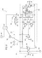
- FIG. 2 illustrates the general hydraulic circuit design of the automatic shift device 20 of a two speed hydrostatic motor 35.
- the design comprises the driving motor or engine 12 which drives a variable displacement pump 33, controlled by the hydro pedal 6, and a charge pump 29.
- the pump 33 is connected to the two speed hydrostatic motor 35 by a first working line 25 (normally called the high pressure side) and the motor 35 is connected to the pump 33 by a second working line 28 (normally called the low pressure side or return line), thereby forming a closed circuit.
- hydraulic fluid is pumped to the motor 35 by the pump 33 through the first working line 25 and returned to the pump 33 through the second working line 28.
- the system further comprises several limiting valves to prevent damage to the system in the event of excess pressures.
- the limiting valves are designed to be triggered when pressures in excess of 3.500 N/cm 2 (appr. 5000 psi) occur in the working lines.
- the limiting valves 26 and 27 are activated allowing the hydraulic fluid in the working lines 25 or 28 to be transferred to a drain 37. This prevents the excess pressure from damaging the motor 35 or other expensive components.
- These limiting valves 26 and 27 are well known to one skilled in the art, and therefore need no further explanation.
- a charge pump valve 30 is provided, designed to open at 140 N/cm 2 (appr. 200 psi) to prevent damage to the charge pump 29. Again, when the valve 30 opens, the hydraulic fluid is allowed to be discharged to a drain 37. It will be appreciated that because the charge pump valve 30 and the limiting valves 26 and 27 open to the drain at 140 N/cm 2 , respectively 3.500 N/cm 2 , the entire system will be protected from excess pressures. Also obvious to one skilled in the art are several filters 38, coolers 39 and drains 37 which are conventional in a hydraulic circuit.
- a pilot valve 40 and a torque valve 45 which both can be moved to two positions.
- the torque valve 45 is connected to the motor swash plate 36 by a pair of cylinders 47 and a pair of orifices 46. As seen in figure 2, the torque valve 45 is biased in the first position 'a'. In this position, any fluid in the cylinders 47 exits through the torque valve drain line 50.
- the torque valve is shifted to the second position 'b' (the valve 45 is moved upwards as viewed in figure 2), fluid from either the first working line 25 or second working line 28 enters one of the orifices 46 and cylinders 47.
- the movement of the torque valve 45 from the first and second positions is controlled by the torque valve line 48 whereas fluid through the torque valve line 48 is controlled by the pilot valve 40.
- the pilot valve 40 also has two positions - a third position (position 'a') and a fourth position (position 'b'). There is a bias spring 41 which actuates the valve 40 into the third position (or 'a' position as seen in figure 2).
- the pilot valve further has a solenoid 42 which, when actuated, moves the pilot valve into the fourth position (position 'b').
- a solenoid 42 which, when actuated, moves the pilot valve into the fourth position (position 'b').
- hydraulic fluid from the charge line 31 and pilot valve line 44 flows to the torque valve line 48.
- This fluid moves the torque valve 45 from the 'a' or first position to the 'b' or second position.
- fluid from the first or second working lines 25 or 28 enters one of the orifices 46 and cylinders 47 and changes the position of the motor swash plate 36 to a position for, on the one hand, increasing the output speed of the hydrostatic motor 35 and, on the other hand, decreasing the output torque.
- the valve 40 when the solenoid 42 is de-activated, the valve 40 is pushed by the bias spring 41 back to the 'a' or third position. This connects the torque valve line 48 to the pilot drain line 43 and to a drain 37. The loss of fluid in the torque valve line 48 moves the torque valve 45 back to the first or 'a' position, which ultimately shifts the motor swash plate 36 to a position for decreasing the output speed but increasing the output torque.
- Controlling the solenoid 42, and hence ultimately the motor swash plate 36 is a controller means 53 which receives electrical signals from a pressure sensor means 54 and a switch means 52. The controller means 53 then sends signals to the solenoid 42 which responds to position the pilot valve 40.
- the pressure sensor means 54 is connected through a pressure sensor line 51 so as to monitor the pressure in the first working line 25.
- an Eclipse pressure transducer manufactured by Data Instruments Inc. is used. It has a range of 70 through 4.900 N/cm 2 (appr. 100 through 7100 psi).
- FIG 3 illustrates the electrical schematic of the switch means 52, controller means 53, the pressure sensor means 54 and solenoid 42.
- the switch means 52 consists of a three-position switch 101 and a two-position switch 102.
- the three positions 1, 2 and 3 of switch 101 correspond to three different settings whereby the operator can set and control the solenoid 42 and consequently the swash plate 36.
- Position 1 results in the solenoid 42 being in the off position, thus resulting in the swash plate 36 and motor 35 remaining in a low speed (and hence high torque) position. If the operator selects position 3, the solenoid is continuously on, resulting in the swash plate 36 and motor 35 being in the high speed setting.
- the auto shift feature of the present invention is activated, whereby the controller 53 uses the pressure detected by the pressure sensor 54 to automatically activate or de-activate the solenoid 42.
- the solenoid 42 will change the position of the pilot valve 40, which in turn positions the torque valve 45, leading, as already explained, to an altered position of the swash plate 36 and a change of the motor's operating speed.
- Switch 102 has only two positions which respectively correspond to the forward or reverse drive direction of the tractor 1.
- the controller means 53 is a conventional controller with seven inputs 111 to 117, and three outputs 118 to 120, as indicated in figure 3.
- the controller 53 receives a first electrical signal (or signals) 115, 116 from the pressure sensing means 54 and transmits a second electrical signal (or signals) 120 from the controller means 53 to the solenoid 42.
- the switch means 52 transmits a third electrical signal (or signals) 111 to 114 from the switch means 52 to the controller means 53.
- the controller means 53 responds to four conditions and composes the second electrical signal (or signals) 120 for sending to the solenoid 42 depending on those conditions. When switch 101 is in position 1, the controller 53 is off and solenoid 42 is off.
- the controller 53 When switch 101 is in position 2, with switch 102 in the "NC" (normally closed) position (which is an indication that the tractor 1 is moving forward), the controller 53 initially activates the solenoid 42 to place the motor 35 in the high speed position. In the meantime, the controller 53 continuously monitors the pressure sensor 54 output signal 115. If the signal 115 indicates a pressure of 2100 N/cm 2 (appr. 3000 psi) or higher (which is an indication that the tractor 1 is experiencing an increased load e.g. by moving into a pile of material), the controller 53 deactivates the solenoid 42 to place the motor 35 in the low speed (but high torque) position.
- the solenoid 42 remains off until switch 102 changes over to the "NO" (normally open) contact position as a result of a shifting into the reverse driving direction, whereafter the controller 53 re-activates the solenoid 42 to obtain the high speed position of the motor 35. This is a logical step in as much as, when reversing the tractor 1 and thus backing up from a pile of material, a lower load on the tractor 1 can be expected.
- the solenoid 42 remains on as long as switch 101 maintains position 2 and switch 102 maintains continuity through the "NO" contact position. A change- over of switch 102 back to the "NC" contact position maintains solenoid 42 'on', but re-sets the controller to monitor the sensor signal to the 2100 N/cm 2 level, as previously described.
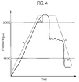
- the controller 53 takes account of an upper and a lower pressure limit. More specifically, in operation, when the operator has selected position 2 on switch 101, the solenoid 42 is initially activated and keeps the motor 35 in the high speed position. The motor remains in the high speed position (a) until the pressure in the first working line 25 exceeds 2.100 N/cm 2 (appr. 3000 psi) for a predetermined interval of time (x), usually 1/30 of a second. At that point, the controller means 53 de-activates the solenoid 42, which shifts the motor into the low speed position (b). This will result in an immediate drop of pressure below 2.100 N/cm 2 but normally still higher than 1.050 N/cm 2 (appr.
- the motor 35 remains in the low speed position, with the solenoid 42 de-activated for as long as the pressure does not drop below the 1.050 N/cm 2 limit. Should the increased load on the tractor disappear for one or other reason, resulting in a pressure drop below the 1.050 N/cm 2 limit for a predetermined interval of time (y), then the controller 53 issues an electrical signal for re-activating the solenoid 42. This again shifts the motor 35 into the high speed position. It will be clear that with the above embodiment, the motor 35 setting is altered each time a pressure is experienced above or below the upper, respectively lower pressure limit. Such an arrangement is convenient in that it continuously responds to varying load conditions of the tractor (e.g. driving uphill or downhill). Of course, the time intervals and pressures can be altered depending on various system requirements.
Landscapes
- Engineering & Computer Science (AREA)
- General Engineering & Computer Science (AREA)
- Mechanical Engineering (AREA)
- Physics & Mathematics (AREA)
- Fluid Mechanics (AREA)
- Control Of Fluid Gearings (AREA)
Applications Claiming Priority (2)
| Application Number | Priority Date | Filing Date | Title |
|---|---|---|---|
| US11161398P | 1998-12-10 | 1998-12-10 | |
| US111613P | 1998-12-10 |
Publications (2)
| Publication Number | Publication Date |
|---|---|
| EP1008785A2 true EP1008785A2 (de) | 2000-06-14 |
| EP1008785A3 EP1008785A3 (de) | 2001-01-03 |
Family
ID=22339477
Family Applications (1)
| Application Number | Title | Priority Date | Filing Date |
|---|---|---|---|
| EP99204190A Withdrawn EP1008785A3 (de) | 1998-12-10 | 1999-12-07 | Automatische Schaltung für einen hydrostatischen Zweigangmotor eines Kleinschleppers |
Country Status (1)
| Country | Link |
|---|---|
| EP (1) | EP1008785A3 (de) |
Cited By (6)
| Publication number | Priority date | Publication date | Assignee | Title |
|---|---|---|---|---|
| WO2008105999A1 (en) * | 2007-02-28 | 2008-09-04 | Caterpillar Inc. | Method and system for feedback pressure control |
| US7469534B2 (en) | 2005-09-26 | 2008-12-30 | Kubota Corporation | Load control structure for work vehicle |
| WO2012119089A1 (en) * | 2011-03-03 | 2012-09-07 | Clark Equipment Company | Automated shifting of hydraulic drive systems |
| US8414454B2 (en) | 2005-09-30 | 2013-04-09 | Kubota Corporation | Speed control structure and method for work vehicle |
| US9347554B2 (en) | 2013-03-14 | 2016-05-24 | Caterpillar Inc. | Hydrostatic drive system |
| WO2020048629A1 (de) * | 2018-09-06 | 2020-03-12 | Bomag Gmbh | Hydrauliksystem mit hydraulikmotor, verfahren zum betrieb und arbeitsmaschine mit derartigem hydrauliksystem |
Citations (1)
| Publication number | Priority date | Publication date | Assignee | Title |
|---|---|---|---|---|
| US5177964A (en) | 1989-01-27 | 1993-01-12 | Hitachi Construction Machinery Co., Ltd. | Hydraulic drive traveling system |
Family Cites Families (7)
| Publication number | Priority date | Publication date | Assignee | Title |
|---|---|---|---|---|
| US4554992A (en) * | 1983-09-09 | 1985-11-26 | Fmc Corporation | Hydraulically operated four wheel sweeper |
| JP2709925B2 (ja) * | 1987-09-30 | 1998-02-04 | カヤバ工業株式会社 | 2速モータの制御装置 |
| JPH0193603A (ja) * | 1987-09-30 | 1989-04-12 | Kayaba Ind Co Ltd | 可変容量型油圧ポンプまたはモータの制御装置 |
| JPH0324366A (ja) * | 1989-06-19 | 1991-02-01 | Kubota Corp | 作業車の走行制御装置 |
| JP3211836B2 (ja) * | 1991-01-22 | 2001-09-25 | カヤバ工業株式会社 | ピストンモータの速度制御装置 |
| JP2609001B2 (ja) * | 1991-04-19 | 1997-05-14 | 株式会社クボタ | 車両の走行制御装置 |
| JP3585261B2 (ja) * | 1994-06-22 | 2004-11-04 | カヤバ工業株式会社 | 油圧モータ |
-
1999
- 1999-12-07 EP EP99204190A patent/EP1008785A3/de not_active Withdrawn
Patent Citations (1)
| Publication number | Priority date | Publication date | Assignee | Title |
|---|---|---|---|---|
| US5177964A (en) | 1989-01-27 | 1993-01-12 | Hitachi Construction Machinery Co., Ltd. | Hydraulic drive traveling system |
Cited By (13)
| Publication number | Priority date | Publication date | Assignee | Title |
|---|---|---|---|---|
| CN101865286A (zh) * | 2005-09-26 | 2010-10-20 | 株式会社久保田 | 作业车的负载控制结构 |
| US7469534B2 (en) | 2005-09-26 | 2008-12-30 | Kubota Corporation | Load control structure for work vehicle |
| CN101865286B (zh) * | 2005-09-26 | 2015-03-11 | 株式会社久保田 | 作业车的负载控制结构 |
| US8414454B2 (en) | 2005-09-30 | 2013-04-09 | Kubota Corporation | Speed control structure and method for work vehicle |
| WO2008105999A1 (en) * | 2007-02-28 | 2008-09-04 | Caterpillar Inc. | Method and system for feedback pressure control |
| US7788917B2 (en) | 2007-02-28 | 2010-09-07 | Caterpillar Inc | Method and system for feedback pressure control |
| WO2012119089A1 (en) * | 2011-03-03 | 2012-09-07 | Clark Equipment Company | Automated shifting of hydraulic drive systems |
| CN102971467A (zh) * | 2011-03-03 | 2013-03-13 | 克拉克设备公司 | 液压驱动系统的自动转换 |
| US20130133319A1 (en) * | 2011-03-03 | 2013-05-30 | Clark Equipment Company | Automated shifting of hydraulic drive systems |
| US9382925B2 (en) * | 2011-03-03 | 2016-07-05 | Clark Equipment Company | Automated shifting of hydraulic drive systems |
| CN102971467B (zh) * | 2011-03-03 | 2017-01-18 | 克拉克设备公司 | 液压驱动系统的自动转换 |
| US9347554B2 (en) | 2013-03-14 | 2016-05-24 | Caterpillar Inc. | Hydrostatic drive system |
| WO2020048629A1 (de) * | 2018-09-06 | 2020-03-12 | Bomag Gmbh | Hydrauliksystem mit hydraulikmotor, verfahren zum betrieb und arbeitsmaschine mit derartigem hydrauliksystem |
Also Published As
| Publication number | Publication date |
|---|---|
| EP1008785A3 (de) | 2001-01-03 |
Similar Documents
| Publication | Publication Date | Title |
|---|---|---|
| US7849952B2 (en) | Tractor with two engine settings | |
| US6644429B2 (en) | Hydrostatic auxiliary drive system | |
| EP0864482A2 (de) | Gerät zur Geschwindigkeitsänderung eines Fahrzeugvorderrades | |
| US12123174B2 (en) | Throttle control system | |
| CA2596403A1 (en) | Tractor with two engine settings | |
| EP1862345B1 (de) | Hydrostatischer fahrantrieb einer arbeitsmaschine | |
| JP7091286B2 (ja) | 作業車両 | |
| EP1008785A2 (de) | Automatische Schaltung für einen hydrostatischen Zweigangmotor eines Kleinschleppers | |
| US4651846A (en) | Rear drive inching control for a four wheel drive vehicle | |
| JP2018003904A (ja) | 作業車両 | |
| JP4966358B2 (ja) | 作業車両の制御装置 | |
| JP4756582B2 (ja) | 作業車両 | |
| US5678469A (en) | Creeper drive system | |
| US8504249B2 (en) | Automatic control of mechanical front wheel drive using speed ratio | |
| JP5035934B2 (ja) | 作業車両 | |
| US8504250B2 (en) | Momentary activation of mechanical front wheel drive | |
| JP2006342840A (ja) | 負荷制御装置 | |
| JP4899487B2 (ja) | トラクタ | |
| JPH04356289A (ja) | 農耕用対地作業車輌の重心位置制御装置 | |
| JP4650930B2 (ja) | 作業車両の制御装置 | |
| CA2417313C (en) | Hydrostatic auxiliary drive system | |
| JP4510657B2 (ja) | 作業車両の制御装置 | |
| JP2023030376A (ja) | 作業車両 | |
| SE518967C2 (sv) | Motordrivet dragfordon | |
| JP4525194B2 (ja) | トラクタ |
Legal Events
| Date | Code | Title | Description |
|---|---|---|---|
| PUAI | Public reference made under article 153(3) epc to a published international application that has entered the european phase |
Free format text: ORIGINAL CODE: 0009012 |
|
| AK | Designated contracting states |
Kind code of ref document: A2 Designated state(s): DE FR GB IT |
|
| AX | Request for extension of the european patent |
Free format text: AL;LT;LV;MK;RO;SI |
|
| PUAL | Search report despatched |
Free format text: ORIGINAL CODE: 0009013 |
|
| AK | Designated contracting states |
Kind code of ref document: A3 Designated state(s): AT BE CH CY DE DK ES FI FR GB GR IE IT LI LU MC NL PT SE |
|
| AX | Request for extension of the european patent |
Free format text: AL;LT;LV;MK;RO;SI |
|
| 17P | Request for examination filed |
Effective date: 20010628 |
|
| AKX | Designation fees paid |
Free format text: DE FR GB IT |
|
| 17Q | First examination report despatched |
Effective date: 20021002 |
|
| RAP1 | Party data changed (applicant data changed or rights of an application transferred) |
Owner name: CNH U.K. LIMITED |
|
| STAA | Information on the status of an ep patent application or granted ep patent |
Free format text: STATUS: THE APPLICATION IS DEEMED TO BE WITHDRAWN |
|
| 18D | Application deemed to be withdrawn |
Effective date: 20030213 |